2A6G6-FCAMF004LED camera floodlight
National State Industries Limited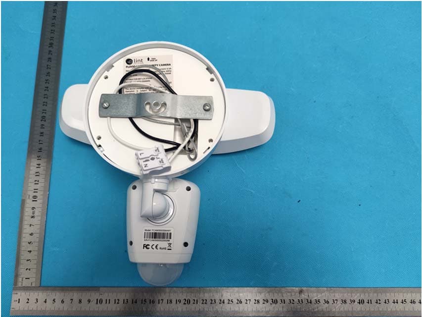
Click to zoom
Application Details
- Equipment Class
- DTS - Digital Transmission System
- Date of Grant
- Jul 16, 2022
- Application Purpose
- Original Equipment
- Date of Application
- Jul 16, 2022
- Equipment Note
- LED camera floodlight
- Frequency Range
- 2412.00000000 - 2462.00000000
- Country
- China
Documents & Files
Document Text
Text extracted from the exhibit documents filed with the FCC. Open a document above to read the original.
Users Manual
FCAM3000SMART INSTALLATION NSTRUCTIONS FLOOD LIGHT SECURITY CAMERA For more support, please email us at [email protected] Your questions will be answered promptly. FCAM3000SMART Note : These instructions assume you are replacing an existing floodlight and/or have a junction box where Floodlight Cam can be mounted. If you don’t have a junction box, you’ll need to hire a certify electrician to install one. SHUT POWER OFF AT THE ELECTRICAL BOX If you don’t know where your breaker is or how to turn off power to your floodlight circuit, consult with a licensed electrician. Note: Only use this part when installing with Exterior Electrical junction boxes 1pc Metal bracket adapter PARTS INCLUDED: REQUIRED TOOLS (NOT INCLUDED) 2X external J-box screws. 3/16 size 2pcs External J-box Screws. 8X32 size 1pc Mounting Cross Bar 1pc Safety Wire 2pcs Quick Connectors 1pc Flood Ligth Camera FCAM3000SMART HOW EVERYTHING GOES TOGETHER: Installation Option #1: Flush-mount Junction Box ` Head Lights PIR Sensor Microphone Camera Lens Hot Wire Deco nuts & rubber washers Safety Wire & hook Quick Connector Mounting Cross Bar Mounting Screws LED Indicator Light Neutral Wire FCAM3000SMART Installation Option #2: Exterior Junction Box Installation Head Lights Quick Connector Mounting Screws Exterior J-box (NOT INCLUDED) Camera Lens Mounting Cross Bar Safety Wire & hook Deco nuts & rubber washers Metal bracket (For External J-box Only) LED Indicator Light Microphone PIR Sensor Black/Hot Wire White/Neutral Wire FCAM3000SMART Bring the PIR sensor down 90°. Rotate the camera head to the right 90° For best performance, the Motion Sensor should be located parallel to the ground. The motion sensor is optimized to detect a human-like object up to 32fts at the height of 9ft above height. MOTION SENSOR AND CAMERA POSITION 9ft 32ft PARALLEL TO GROUND BEFORE INSTALLING Floodlight Cam ships with the camera upside down on the fixture. Ensure to rotate the camera head so that the PIR sensor is parallel to the ground. Bring the camera head to the front. FCAM3000SMART FLUSH MOUNT JUNTION-BOX INSTRUCTION NOTE: for this installation method you DO-NOT need the round metal Bracket 1. INSTALLING THE CROSS-BAR BRACKET • Install mounting cross bracket to the junction box using J-box mounting screws. 2. HANG THE FLOODLIGHT FOR EASY CONNECTION • Use the provided safety wire and hook to hang the Floodlight Camera from the mounting cross bracket. FCAM3000SMART 6. TURN POWER ON Restore power at the electrical breaker box. 3. CONNECT THE POWER LINES. • Connect the Hot/line wire from the junction box to the black wire from the floodlight camera using the provided connector. Open the clamping unit from the connector and close it once the wire is fully inserted. • Connect the Neutral wire from the junction box to the white from the floodlight camera using the provided connector. Open the clamping unit from the connector and close it once the wire is fully inserted. • Connect the ground wire to the green ground screw on the bracket. Note: the ground wire only goes to the metal crossbar. The fixture does not need to be ground. 4. PLACE THE FLOODLIGHT CAMERA ON THE CROSSBAR • Carefully push all the wires through the openings. • Align the mounting post with the holes on Floodlight Camera and press together. • Install rubber washer and deco nuts to secure the fixture. Tight firmly using your hand. 5. APPLY SILICONE • Add silicone sealant around the canopy between the metal plate and J-box as well as the metal plate and canopy. This will prevent moisture from getting to the wiring compartment. FCAM3000SMART EXTERNAL JUNCTION-BOX INSTALLATION Note: for this installation method you need the round metal Bracket and 3/16 screws 1. INSTALLING MOUNTING CROSSBAR AND METAL BRACKET ADAPTER: • Using the exterior J-box mounting screws, 3/16 x 0.5in (shorter screw) , install mounting crossbar and metal bracket adapter to the junction. 2. HANG FLOODLIGHT FOR EASY CONNECTION • Use the provided safety wire and clip to hang the Floodlight Camera from the mounting cross bracket. FCAM3000SMART 6. TURN POWER ON Restore power at the electrical breaker box. 3. CONNECT THE POWER LINES. • Connect the Hot/line wire from the junction box to the black wire from the floodlight camera using the provided connector. Open the clamping unit from the connector and close it once the wire is fully inserted. • Connect the Neutral wire from the junction box to the white from the floodlight camera using the provided connector. Open the clamping unit from the connector and close it once the wire is fully inserted. • Connect the ground wire to the green ground screw on the bracket. Note: the ground wire only goes to the metal crossbar. The fixture does not need to be ground. 4. PLACE THE FLOODLIGHT CAMERA ON THE CROSSBAR • Carefully push all the wires through the openings. • Align the mounting post with the holes on Floodlight Camera and press together. • Install rubber washer and deco nuts to secure the fixture. Tight firmly using your hand. 5. APPLY SILICONE • Add silicone sealant around the canopy between the metal plate and J-box as well as the metal plate and canopy. This will prevent moisture from getting to the wiring compartment. FCAM3000SMART Warni ngs: 1. This product may represent a possible shock or fire hazar d if improperly inst alled. 2. The product should be inst alled following the owner’s manual, ele ctr ical codes, and/or the current National Ele ctr ic Code (NEC). 3. Use only UL or IEC approved wire for input/output connections. 4. Use only on 120-volt 60Hz circuits . 5. Do not use with dimmers. 6. RI SK OF SHOCK: ensure always remember to tu rn Off the Power from the ele ctr ic al panel box before you install the fixtu re. 7. Before installing the security camera fixture, revie w thoroughly this installation manual. Consult a qualified ele ctr ic ian If you do not have sufficie nt experie nce. FCC Stat ement: This device complie s with part 15 of the FCC Rules. Operatio…
Text truncated - open the document above for the full version.
External Photos
Reference No.: WTX22X06112236W Page 2 of 13 Waltek Testing Group (Shenzhen) Co., Ltd. Http://www.waltek.com.cn EXHIBIT 2 - EUT EXTERNAL PHOTOGRAPHS EUT View 1 EUT View 2 Reference No.: WTX22X06112236W Page 3 of 13 Waltek Testing Group (Shenzhen) Co., Ltd. Http://www.waltek.com.cn EUT View 3 EUT View 4 Reference No.: WTX22X06112236W Page 4 of 13 Waltek Testing Group (Shenzhen) Co., Ltd. Http://www.waltek.com.cn EUT View 5 EUT View 6
ID Label/Location Info
Reference No.: WTX22X06112236W Page 1 of 13 Waltek Testing Group (Shenzhen) Co., Ltd. Http://www.waltek.com.cn ANNEX EXHIBIT 1 - PRODUCT LABELING Proposed FCC ID Label Format Specifications: The label shall be securely affixed to a permanently attached part of the device, in a location where it is visible or easily accessible to the user, and shall not be readily detachable. The label shall be sufficiently durable to remain fully legible and intact on the device in all normal conditions of use throughout the device’s expected lifetime. Proposed Label Location on EUT FCC ID Label Location
Internal Photos
Reference No.: WTX22X06112236W Page 5 of 13 Waltek Testing Group (Shenzhen) Co., Ltd. Http://www.waltek.com.cn EXHIBIT 3 - EUT INTERNAL PHOTOGRAPHS EUT Housing and Board View 1 EUT Housing and Board View 2 Reference No.: WTX22X06112236W Page 6 of 13 Waltek Testing Group (Shenzhen) Co., Ltd. Http://www.waltek.com.cn EUT Housing and Board View 3 EUT Housing and Board View 4 Reference No.: WTX22X06112236W Page 7 of 13 Waltek Testing Group (Shenzhen) Co., Ltd. Http://www.waltek.com.cn Solder Board-Component View 1 Solder Board-Component View 2 Reference No.: WTX22X06112236W Page 8 of 13 Waltek Testing Group (Shenzhen) Co., Ltd. Http://www.waltek.com.cn Solder Board-Component View 3 Solder Board-Component View 4 Reference No.: WTX22X06112236W Page 9 of 13 Waltek Testing Group (Shenzhen) Co., Ltd. Http://www.waltek.com.cn Solder Board-Component View 5 Solder Board-Component View 6 Reference No.: WTX22X06112236W Page 10 of 13 Waltek Testing Group (Shenzhen) Co., Ltd. Http://www.waltek.com.cn Antenna View
RF Exposure Info
1. MAXIMUM PERMISSIBLE EXPOSURE (MPE) 1.1 General Information Client Information Applicant: National State Industries Ltd. Address of applicant: Wulian Industrial Park, FengGang Town, DongGuan City, GuangDong Province 523695 Manufacturer: National State Industries Ltd. Address of manufacturer: Wulian Industrial Park, FengGang Town, DongGuan City, GuangDong Province 523695 General Description of EUT: Product Name: LED camera floodlight Trade Name: Naspil Model No.: FCAM/F004/3000/850-WT Adding Model(s): FCAM3000SMART, FCAM/F004/XXXX/YZZ-AAAA,Declared by the applicant that XXXX denotes Lumen, Y for CRI, ZZ for CCT,AAAA for Finish Color Rated Voltage: AC 120V 60Hz Power Adapter / FCC ID: 2A6G6-FCAMF004 Equipment Type: Fixed device Technical Characteristics of EUT: Wi-Fi Support Standards: 802.11b, 802.11g, 802.11n Frequency Range: 2412-2462MHz for 802.11b/g/n(HT20) 2422-2452MHz for 802.11n(HT40) RF Output Power: 15.71dBm (Conducted) Type of Modulation: CCK, OFDM, QPSK, BPSK, 16QAM, 64QAM Quantity of Channels: 11 for 802.11b/g/n(HT20); 7 for 802.11n(HT40) Channel Separation: 5MHz Type of Antenna: PCB Antenna Antenna Gain: 3dBi 1.2 Standard Applicable According to §1.1307(b)(1) and KDB 447498 D01 General RF Exposure Guidance v06, system operating under the provisions of this section shall be operating in a manner that the public is not exposed to radio frequency energy level in excess limit for maximum permissible exposure. (a) Limits for Occupational / Controlled Exposure Frequency range (MHz) Electric Field Strength (E) (V/m) Magnetic Field Strength (H) (A/m) Power Density (S) (mW/cm 2 ) Averaging Times | E | 2 , | H | 2 or S (minutes) 0.3-3.0 614 1.63 (100)* 6 3.0-30 1842/f 4.89/f (900/f)* 6 30-300 61.4 0.163 1.0 6 300-1500 / / F/300 6 1500-100000 / / 5 6 (b) Limits for General Population / Uncontrolled Exposure Frequency range (MHz) Electric Field Strength (E) (V/m) Magnetic Field Strength (H) (A/m) Power Density (S) (mW/cm 2 ) Averaging Times | E | 2 , | H | 2 or S (minutes) 0.3-1.34 614 1.63 (100)* 30 1.34-30 824/f 2.19/f (180/f)* 30 30-300 27.5 0.073 0.2 30 300-1500 / / F/1500 30 1500-100000 / / 1 30 Note: f = frequency in MHz: * = Plane-wave equivalents power density 1.3 MPE Calculation Method S = (30*P*G) / (377*R 2 ) S = power density (in appropriate units, e.g., mw/cm 2 ) P = power input to the antenna (in appropriate units, e.g., mw) G = power gain of the antenna in the direction of interest relative to an isotropic radiator, the power gain factor is normally numeric gain. R = distance to the center of radiation of the antenna (in appropriate units, e.g., cm) 1.4 MPE Calculation Result For Wi-Fi Maximum Tune-Up output power: 16(dBm) Maximum peak output power at antenna input terminal: 39.81(mW) Prediction distance: >20(cm) Prediction frequency: 2412 (MHz) Antenna gain: 3 (dBi) Directional gain (numeric gain): 2.00 The worst case is power density at prediction frequency at 20cm: 0.0158(mw/cm 2 ) MPE limit for general population exposure at prediction frequency: 1 (mw/cm 2 ) Result: Pass
Test Report
Waltek Testing Group (Shenzhen) Co., Ltd. Http://www.waltek.com.cn Page 1 of 58 TEST REPORT Reference No. .................... : WTX22X06112236W FCC ID ................................ : 2A6G6-FCAMF004 Applicant ........................... : National State Industries Ltd. Address.............................. : Wulian Industrial Park, FengGang Town, DongGuan City, GuangDong Province 523695 Manufacturer ..................... : The same as Applicant Address.............................. : The same as Applicant Product Name ................... : LED camera floodlight Model No... ......................... : FCAM/F004/3000/850-WT Standards .......................... : FCC Part 15.247 Date of Receipt sample .... : 2022-06-06 Date of Test........................ : 2022-06-06 to 2022-07-14 Date of Issue ..................... : 2022-07-14 Test Report Form No. ....... : WTX_Part 15_247W Test Result ......................... : Pass Remarks: The results shown in this test report refer only to the sample(s) tested, this test report cannot be reproduced, except in full, without prior written permission of the company. The report would be invalid without specific stamp of test institute and the signatures of approver. Prepared By: Waltek Testing Group (Shenzhen) Co., Ltd. Address: 1/F., Room 101, Building 1, Hongwei Industrial Park, Liuxian 2nd Road, Block 70 Bao'an District, Shenzhen, Guangdong, China Tel.: +86-755-33663308 Fax.: +86-755-33663309 Email: [email protected] Tested by: Approved by: Dashan Chen Silin Chen Reference No.: WTX22X06112236W Waltek Testing Group (Shenzhen) Co., Ltd. Http://www.waltek.com.cn Page 2 of 58 TABLE OF CONTENTS 1. GENERAL INFORMATION ...................................................................................................................................4 1.1 PRODUCT DESCRIPTION FOR EQUIPMENT UNDER TEST (EUT) ...............................................................................4 1.2 TEST STANDARDS ...................................................................................................................................................5 1.3 TEST METHODOLOGY .............................................................................................................................................5 1.4 TEST FACILITY .......................................................................................................................................................5 1.5 EUT SETUP AND TEST MODE .................................................................................................................................6 1.6 MEASUREMENT UNCERTAINTY ..............................................................................................................................7 1.7 TEST EQUIPMENT LIST AND DETAILS .....................................................................................................................8 2. SUMMARY OF TEST RESULTS ......................................................................................................................... 10 3. ANTENNA REQUIREMENT ................................................................................................................................ 11 3.1 STANDARD APPLICABLE ....................................................................................................................................... 11 3.2 EVALUATION INFORMATION................................................................................................................................. 11 4. POWER SPECTRAL DENSITY ........................................................................................................................... 12 4.1 STANDARD APPLICABLE ....................................................................................................................................... 12 4.2 TEST SETUP BLOCK DIAGRAM ............................................................................................................................. 12 4.3 TEST PROCEDURE ................................................................................................................................................. 12 4.4 SUMMARY OF TEST RESULTS/PLOTS .................................................................................................................... 12 5. DTS BANDWIDTH ................................................................................................................................................. 13 5.1 STANDARD APPLICABLE ....................................................................................................................................... 13 5.2 TEST SETUP BLOCK DIAGRAM ............................................................................................................................. 13 5.3 TEST PROCEDURE ................................................................................................................................................. 13 5.4 SUMMARY OF TEST RESULTS/PLOTS .................................................................................................................... 13 6. RF OUTPUT POWER ............................................................................................................................................ 14 6.1 STANDARD APPLICABLE ....................................................................................................................................... 14 6.2 TEST SETUP BLOCK DIAGRAM ............................................................................................................................. 14 6.3 TEST PROCEDURE ................................................................................................................................................. 14 6.4 SUMMARY OF TEST RESULTS/PLOTS .................................................................................................................... 14 7. FIELD STRENGTH OF SPURIOUS EMISSIO…
Text truncated - open the document above for the full version.
Test Setup Photos
Reference No.: WTX22X06112236W Page 11 of 13 Waltek Testing Group (Shenzhen) Co., Ltd. Http://www.waltek.com.cn EXHIBIT 4 - TEST SETUP PHOTOGRAPHS Conducted Emission Test Setup Radiation Emission Test Setup (Below 30MHz) Reference No.: WTX22X06112236W Page 12 of 13 Waltek Testing Group (Shenzhen) Co., Ltd. Http://www.waltek.com.cn Radiation Emission Test Setup (30MHz to 1GHz) Radiation Emission Test Setup (1GHz to 18GHz) Reference No.: WTX22X06112236W Page 13 of 13 Waltek Testing Group (Shenzhen) Co., Ltd. Http://www.waltek.com.cn Radiation Emission Test Setup (Above 18GHz) ***** END OF REPORT *****
Contact Information
Applicant
Crystal Liu(Manager)
Test Firm
Waltek Testing Group (Shenzhen) Co., Ltd.Jandy So
Technical Specifications
| # | Rule Parts | Frequency Range | Power Output |
|---|---|---|---|
| 1 | 15C | 2.41 GHz - 2.46 GHz | 37.20 mW |