2A6GT-GLCSNTCSL001Strip Lights S11
glocusent co., ltd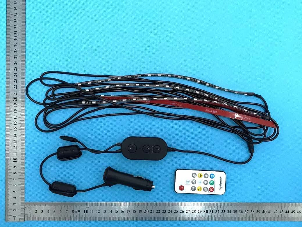
Click to zoom
Application Details
- Equipment Class
- DTS - Digital Transmission System
- Date of Grant
- Jun 19, 2022
- Application Purpose
- Original Equipment
- Date of Application
- Jun 19, 2022
- Equipment Note
- Strip Lights S11
- Frequency Range
- 2402.00000000 - 2480.00000000
- Company
- glocusent co., ltd
- Country
- United States
Documents & Files
Document Text
Text extracted from the exhibit documents filed with the FCC. Open a document above to read the original.
Users Manual
C笃~glocusent 飞~I 'l' -LlGHTUPYOURUFE - LED STRIP LlGHTS FOR CAR w。晴FromThe Product Dn均ner Hi friends, This is Mason from Glocusønt, and it is so nicø to connøct with you through our口riginaldesigned product. When we cr回扣ethe brand Glocusent, we always hope our Glocu曹ent IIght can shlne In dlfferent corners of your 1怖。'.The atmospheres IIghtlng for ca陪Isour next s回pfoll口wedby 以:>ekr8ading light, pl田S8allow mø to introducø our V8ry first car strip light What Is the maln d附erencefrom Glocusent∞r strlp IIght and othør car strlp IIghts? Our tøam 90t almost all thø best-selling strip lights in the market to try their music mode, we found that none of them has a perfect or even remotely nice music mode. The rhythm of the dancing light Is JUst loolc: IIlc:e It Is sync回wlththe muslc, but dls叩阳Int ødly It Is not r8ally. That Is why we døcldød to gathør口 team to develop口urown smart chip and malc:e sure the strip light can match the music better than all other strip Iight9 that are in the marlc:et. Aftør onø y8町,andhundr回sof timøs studying, døvøloping, testing, and re-d田eloping,we finally cr回tedthe strip light that can carry out the best performance 1 Con由dently saylng, the unlque muslc sync e何ect0' thls Slrlp IIght wlth 。dvan国dnolse cancellatlon tE刷nologycan truly brlng you an immersivø music and romantic world. w。晴FromThe Product Dn均ner Imaging that, under the blue sky with a cl回nmilkyway, you are drlvlng wlth frlends, the car LED IIghts automatlcally shlne brlghtness and color follow回wlththe rhythm and melody of your favorlte music! Now , follow our detall9d lnstallatlon gulde, treat your回If wlth口n阳drlvlngexperlence! Thank you for your suppo此, Slncerely, Mason Product Detalls Cig口ret!e啕hteri 「 Infr口redReceiver LED Strip Lights 们。抖←PowerBut!on k3抖_Brightness 川、注乡什Button 山」市'卡-Mode button I"stal阳tfon 1. P",paratlon 1.1 Open the package and spr回dthe slrlp IIghtS. EK 1.3 Tear 0何the3M glue on the back of the口ttached controller. 1.2 Plug the cigare忧e I1ght9r Into the clgarett9 I1ghter soclcet of the center console. 1.4 Stlclc theα四:ached conlroller near the 。rmr田tbox. I"stal阳tfon 1.5 Unfold the strlp IIghts and Install曾回mIn the posltlon shown Inthe啊gurebelow. Please Instoll酌e2 strlp IIghts 民hind阶efront seat first, and then instali the 2 strip lights in front of the front seat. If the Installing su向ceIsco民Ical,please甜estep 2. If It Is fcbrlc, ple口sesee step 3. 。当一叫叩 I"stal阳tfon 2. For Conlcal Surface 2.1 Cløan and dry thø 2.2 Tøar口付thørød plastlc cortlcal surfacø bøhlnd and fllm on thø baclc: of thø in front of阶efront seat • strip lights. 2.3 Paste strip lights on the 2.4 If needed. use the cløaned surface and press buckl嗣tofIX the ends of over lt about 10-15& . &trlp IIght&. I"stal阳tfon 3. For Fabrlc Surface 3.1 Use plastlc I∞k straps and pull tlghtly to fIX the strip lights' po唱ition. 3.2 Use sclssors to cut off the extra por恒ofthe plastlc lock straps to ~回pyour car tidy. P阳回elOC虫SIrOps同ostleLOC:lr:!JtI'OptPkIItIçLocll:曲'因 4. Ught up th. strlp IIgh恒. 4.1 Press the button on 4.2 Press the power bu忧on the cigarette lighter. on the a忱。chedcontroller. Installatlon 4.3 The strip lights will light up. L」 4.5 Always point the remote control towards the infrared receiver when using it to control the strip lights. 4.4 Remove the plastic film from the remote control. 4.6 Use the attached controller. remote control and APP to control the strip lights Attached Con恼。11... • • • I!i.ra # ③MO阳 Prass Onca Press TWIC。 防。88Thr回Tlm回 @PoWer PressOnce ~、 •...If) TurnlnaOn IOff ~ 。吨htnessLevel ••? Y r 严SlngleColor Mode ~ Muslc SVnc Mode ~s饵neMode Remote COntrol • 。øe Gard町、 8国『咽RalnbawS国no霉国r叩Soenø 4D @ 4D RedCOlor Gr四nCOl田BlueCOI田 "Glocusent L1ght" APP 1. Download "Glocusent Light" 2. Press OK button allow APP in Apple Store (iOS) or the app accesses to Google Play (Android). Bluetooth. tjIM 应噩E 3. Make sure both the 4. Back t口theAPP interface. power 01 the strip lights accept Agreement and 。ndthe Bluetooth on your Privacy Policy. phone are turned on. "Glocusent L1ght" APP 5. Add device, and connect the strip lights. 7. Enter the home page after connection. Slide brightness icon to adjust the brightness as needed 6. Find device and click the "link" icon. 8. There are multiple scene modes, single color, 。ndmusic mode available for different scenarios for you to enjoy "Glocusent L1ght" APP 9. In music mode, there are sensitive and tardy levels to select. When the environment is quiet, sensitive level is suitable When it is loud, please select tardy level. 10. In single color mode you can choose different color modes or set different combinations according to your own preferences. FCC Warning This device complies with Part 15 of the FCC Rules. Operation is subject to the following two conditions: (1) This device may not cause harmful interference, and (2) this device must accept any interference received, including interference that may cause undesired operation. NOTE 1: This equipment has been tested and found to comply with the limits for a Class B digital device, pursuant to part 15 of the FCC Rules. These limits are designed to provide reasonable protection against harmful interference in a residential installation. This equipment generates uses and can radiate radio frequency energy and, if not installed and used in accordance with the instructions, may cause harmful interference to radio communications. However, there is no guarantee that interference will not occur in a particular installation. If this equipment does cause harmful interference to radio or television reception, which can be determined by turning the equipment off and on, the user is encouraged to try to correct the interference by one or more of the following measures: - Reorient or relocate the receiving antenna. - Increase the separation between the equipment and receiver. -Connect the equipment into an outlet on a circuit different from that to which the receiver is connected. -Consult the dealer or an experienced radio/TV technician for help. NOTE …
Text truncated - open the document above for the full version.
Cover Letter(s)
glocusent co., ltd 1624 Market Street ste 226#79525 , Denver, Colorado 80202, United States --------------------------------------------------------------------------------------------------------------------- Date: 2022-06-12 Federal Communications Commission Authorization and Evaluation Division 7435 Oakland Mills Road Columbia, MD 21046 FCC ID:2A6GT-GLCSNTCSL001 ConfidentialityRequest Towhomitmayconcern, PursuanttoSections0.457and0.459oftheCommission’sRules,weherebyrequestconfidential treatmentoftheinformationaccompanyingthisapplicationasoutlinedbelow: ☒BlockDiagram☐Tune-UpInformation ☒ OperationalDescription ☐ SecurityInformation ☒Schematics☐SoftwareDefinedRadio(SDR)Information ☐ PartsList Theabovematerialscontaintradesecretsandproprietaryinformationnotcustomarilyreleasedto thepublic.Thepublicdisclosureofthesematerialsmaybeharmfultotheapplicantandprovide unjustifiedbenefitstoitscompetitors. TheapplicantunderstandsthatpursuanttoSection0.457oftheRules,disclosureofthis applicationandallaccompanyingdocumentationwillnotbemadebeforethedateoftheGrantfor thisapplication. Sincerely, glocusentco.,ltd ------------------------------- (Manchuan Wu) (Manager)
Cover Letter(s)
glocusent co., ltd 1624 Market Street ste 226#79525 , Denver, Colorado 80202, United States -------------------------------------------------------------------------------- (FCC ID:2A6GT-GLCSNTCSL001) POWER OF ATTORNEY DATE: 2022-06-16 Federal Communications Commission Authorization and Evaluation Division 7435 Oakland Mills Road Columbia, MD 21046 To Whom It May Concern: We, the undersigned, hereby authorize Waltek Testing Group (Shenzhen) Co., Ltd. Jandy So on our behalf, to apply to the Federal Communications Commission on our equipment. Any and all acts carried out by Waltek Testing Group (Shenzhen) Co., Ltd. Jandy So on our behalf shall have the same effect as acts of our own. This is to advise that we are in full compliance with the Anti-Drug Abuse Act. We, glocusent co., ltd are not subject to a denial of federal benefits pursuant to Section 5301 of the Anti-Drug Act of 1988, 21 USC853a, and no party to the application is subject to a denial of federal benefits pursuant to that section. Sincerely, glocusent co.,ltd ------------------------------- (Manchuan Wu) (Manager)
External Photos
Reference No.: WTX22X02015940W-1 Page 2 of 11 Waltek Testing Group (Shenzhen) Co., Ltd. Http://www.waltek.com.cn EXHIBIT 2 - EUT EXTERNAL PHOTOGRAPHS EUT View 1 EUT View 2 Reference No.: WTX22X02015940W-1 Page 3 of 11 Waltek Testing Group (Shenzhen) Co., Ltd. Http://www.waltek.com.cn EUT View 3 EUT View 4 Reference No.: WTX22X02015940W-1 Page 4 of 11 Waltek Testing Group (Shenzhen) Co., Ltd. Http://www.waltek.com.cn EUT View 5 EUT View 6 Reference No.: WTX22X02015940W-1 Page 5 of 11 Waltek Testing Group (Shenzhen) Co., Ltd. Http://www.waltek.com.cn EUT View 7 EUT View 8 Reference No.: WTX22X02015940W-1 Page 6 of 11 Waltek Testing Group (Shenzhen) Co., Ltd. Http://www.waltek.com.cn EUT View 9
ID Label/Location Info
Reference No.: WTX22X02015940W-1 Page 1 of 11 Waltek Testing Group (Shenzhen) Co., Ltd. Http://www.waltek.com.cn ANNEX EXHIBIT 1 - PRODUCT LABELING Proposed FCC ID Label Format Specifications: The label shall be securely affixed to a permanently attached part of the device, in a location where it is visible or easily accessible to the user, and shall not be readily detachable. The label shall be sufficiently durable to remain fully legible and intact on the device in all normal conditions of use throughout the device’s expected lifetime. Proposed Label Location on EUT FCC ID Label Location
Internal Photos
Reference No.: WTX22X02015940W-1 Page 7 of 11 Waltek Testing Group (Shenzhen) Co., Ltd. Http://www.waltek.com.cn EXHIBIT 3 - EUT INTERNAL PHOTOGRAPHS EUT Housing and Board View 1 Solder Board-Component View 1 Reference No.: WTX22X02015940W-1 Page 8 of 11 Waltek Testing Group (Shenzhen) Co., Ltd. Http://www.waltek.com.cn Solder Board-Component View 2 Solder Board-Component View 3 Reference No.: WTX22X02015940W-1 Page 9 of 11 Waltek Testing Group (Shenzhen) Co., Ltd. Http://www.waltek.com.cn Solder Board-Component View 4 Antenna View
RF Exposure Info
RF Exposure Requirements Product Description: Strip Lights S11 Model No.: GLCSNTCSL001, GLCSNTCSL002, GLCSNTCSL003 FCC ID: 2A6GT-GLCSNTCSL001 According to the KDB 447498 D01 v06 section 4.3.1, for 100 MHz to 6 GHz and test separation distances ≤ 50 mm, the 1-g and 10-g SAR test exclusion thresholds are determined by the following: [(max. power of channel, including tune-up tolerance, mW)/(min. test separation distance, mm)] ꞏ [√f(GHz)] ≤ 3.0 for 1-g SAR and ≤ 7.5 for 10-g extremity SAR, where - f(GHz) is the RF channel transmit frequency in GHz - Power and distance are rounded to the nearest mW and mm before calculation - The result is rounded to one decimal place for comparison Calculation Result: Bluetooth Tx frequency range: 2402-2480MHz Min. test separation distance: 5mm Maximum Conducted Output Power: -6.05dBm Tune-Up output power: -6.0dBm RF channel transmit frequency: 2402MHz Result: 0.08 Limit: 3.0 The exclusion thresholds is 0.08 < 3, so the transmitter complies with the RF exposure requirements and the SAR is not required.
Test Report
Waltek Testing Group (Shenzhen) Co., Ltd. Http://www.waltek.com.cn Page 1 of 37 TEST REPORT Reference No. ....................: WTX22X02015940W-1 FCC ID ............................... .: 2A6GT-GLCSNTCSL001 Applicant .......................... .: glocusent co., ltd Address ............................ .: 1624 Market Street ste 226#79525 , Denver, Colorado 80202, United States Manufacturer .................... .: Shenzhen Glocusent Technology Co., Ltd Address ............................ .: Room 1703, Building 13, Keenstar Building, Xin’an Street, Bao’An District, Shenzhen Product Name .................. .: Strip Lights S11 Model No.. ......................... .: GLCSNTCSL001 Standards ......................... .: FCC Part 15.247 Date of Receipt sample ... .: 2022-02-10 Date of Test....................... .: 2022-02-10 to 2022-04-15 Date of Issue .................... .: 2022-04-15 Test Report Form No. ...... . : WTX_Part 15_247W Test Result ........................ .: Pass Remarks: The results shown in this test report refer only to the sample(s) tested, this test report cannot be reproduced, except in full, without prior written permission of the company. The report would be invalid without specific stamp of test institute and the signatures of approver. Prepared By: Waltek Testing Group (Shenzhen) Co., Ltd. Address: 1/F., Room 101, Building 1, Hongwei Industrial Park, Liuxian 2nd Road, Block 70 Bao'an District, Shenzhen, Guangdong, China Tel.: +86-755-33663308 Fax.: +86-755-33663309 Email: [email protected] Tested by: Approved by: Jack Huang Silin Chen Reference No.: WTX22X02015940W-1 Waltek Testing Group (Shenzhen) Co., Ltd. Http://www.waltek.com.cn Page 2 of 37 TABLE OF CONTENTS 1. GENERAL INFORMATION ................................................................................................................................... 4 1.1 PRODUCT DESCRIPTION FOR EQUIPMENT UNDER TEST (EUT) ............................................................................... 4 1.2 TEST STANDARDS ................................................................................................................................................... 5 1.3 TEST METHODOLOGY ............................................................................................................................................. 5 1.4 TEST FACILITY ....................................................................................................................................................... 5 1.5 EUT SETUP AND TEST MODE ................................................................................................................................. 6 1.6 MEASUREMENT UNCERTAINTY .............................................................................................................................. 7 1.7 TEST EQUIPMENT LIST AND DETAILS ..................................................................................................................... 8 2. SUMMARY OF TEST RESULTS ......................................................................................................................... 12 3. ANTENNA REQUIREMENT ................................................................................................................................ 13 3.1 STANDARD APPLICABLE ....................................................................................................................................... 13 3.2 EVALUATION INFORMATION ................................................................................................................................ 13 4. POWER SPECTRAL DENSITY ........................................................................................................................... 14 4.1 STANDARD APPLICABLE ....................................................................................................................................... 14 4.2 TEST SETUP BLOCK DIAGRAM ............................................................................................................................. 1 4 4.3 TEST PROCEDURE ................................................................................................................................................. 14 4.4 SUMMARY OF TEST RESULTS/PLOTS .................................................................................................................... 14 5. DTS BANDWIDTH ................................................................................................................................................. 15 5.1 STANDARD APPLICABLE ....................................................................................................................................... 15 5.2 TEST SETUP BLOCK DIAGRAM ............................................................................................................................. 1 5 5.3 TEST PROCEDURE ................................................................................................................................................. 15 5.4 SUMMARY OF TEST RESULTS/PLOTS .................................................................................................................... 15 6. RF OUTPUT POWER ............................................................................................................................................ 16 6.1 STANDARD APPLICABLE ....................................................................................................................................... 16 6.2 TEST SETUP BLOCK DIAGRAM ............................................................................................................................. 1 6 6.3 TEST PROCEDURE ................................................................................................................................................. 16 6.4 SUMMARY OF TEST RESULTS/PLOTS .............................................................................................…
Text truncated - open the document above for the full version.
Test Setup Photos
Reference No.: WTX22X02015940W-1 Page 10 of 11 Waltek Testing Group (Shenzhen) Co., Ltd. Http://www.waltek.com.cn EXHIBIT 4 - TEST SETUP PHOTOGRAPHS Radiation Emission Test Setup (Below 30MHz) Radiation Emission Test Setup (30MHz to 1GHz) Reference No.: WTX22X02015940W-1 Page 11 of 11 Waltek Testing Group (Shenzhen) Co., Ltd. Http://www.waltek.com.cn Radiation Emission Test Setup (1GHz to 18GHz) Radiation Emission Test Setup (Above 18GHz) ***** END OF REPORT *****
Contact Information
Applicant
Manchuan Wu(Manager)
Test Firm
Waltek Testing Group (Shenzhen) Co., Ltd.Jandy So
Technical Specifications
| # | Rule Parts | Frequency Range | Power Output |
|---|---|---|---|
| 1 | 15C | 2.40 GHz - 2.48 GHz | 200.00 µW |
Other Applications from glocusent co., ltd
2A6GTGLCSNTN1201
Aug 02, 2024Starry Sky Lamp
Equipment Class
DSS - Part 15 Spread Spectrum Transmitter