2A6OI-013BRFRecce 360 Mini Camera
Bounce Imaging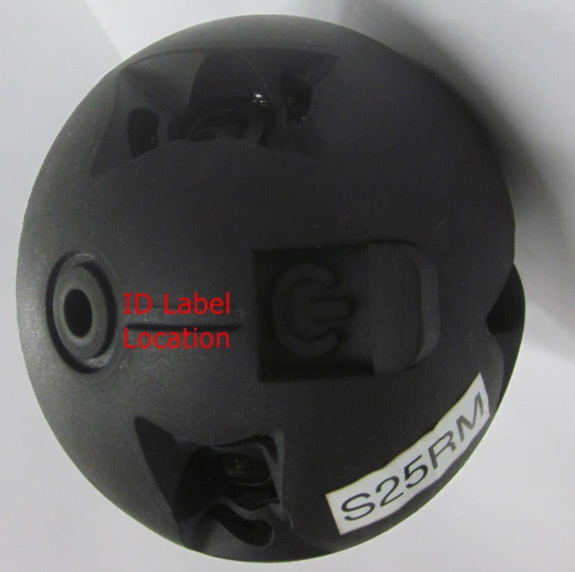
Click to zoom
Application Details
- Equipment Class
- DTS - Digital Transmission System
- Date of Grant
- Sep 26, 2022
- Application Purpose
- Original Equipment
- Date of Application
- Sep 22, 2022
- Equipment Note
- Recce 360 Mini Camera
- Frequency Range
- 2417.00000000 - 2457.00000000
- Company
- Bounce Imaging
- Country
- United States
Documents & Files
Document Text
Text extracted from the exhibit documents filed with the FCC. Open a document above to read the original.
Users Manual
Operating Manual Recce 360 mini 01 West Seneca Street, Floor 24, Buffalo, NY 14203 http://www.bounceimaging.com Operating Manual - Recce 360 mini (V2.0 20220524) 1. Background3 2. Camera overview3 2.1 Recce 3604 2.1.1 Top view4 2.1.2 Controls view5 2.1.3 Bottom view6 2.2 Recce 360 mini7 2.2.1 Top view7 2.2.2 Controls view8 2.2.3 Bottom view9 3. Operating instructions10 3.1 Unpacking10 3.2 Charging10 3.3 Power up10 3.3.1 Checking power state10 3.4 Operating10 3.4.1 WiFi Connection11 3.4.2 Battery run time11 3.4.3 Thermal protection12 3.5Power-down12 3.6 Attaching accessories13 4. Storage13 5. Maintenance13 5.1 Cleaning13 5.2 Servicing14 6. Troubleshooting and diagnostics14 6.1 Battery and charging14 6.2 Power up - power down14 6.3 Connecting to the camera15 6.4 Image quality15 6.5 Audio quality16 6.6 Range - frame rate17 6.7 Scene illumination17 7. Safety guidelines18 7.1 Handling18 Operating Manual - Recce 360 mini (V2.0 20220524) 7.2 Information security19 1. Background This document contains comprehensive instructions for unpacking, setup, calibration, power up, operating, power down, storage, maintenance, and troubleshooting of the system. It also outlines safety guidelines for operating the system. This document does not cover using the accompanying app. For instructions on using the app, please refer to theApp Manual. Related documents: -App manual -Datasheet Recce 360 mini 2. Camera overview The Recce 360 mini provides users with real-time, omnidirectional video. It features an extended range, a speaker for two-way audio, encryption over the wifi feed, and user-friendly ruggedized ports and switches. Operating Manual - Recce 360 mini (V2.0 20220524) 2.1 Recce 360 mini 2.1.1 Top view Fig 4.Top viewRecce 360 mini A.Power button/charger socket protection flap. When pressed this controls the power button. When the flap is lifted (see figure 2), it exposes the charge socket and indicator LED’s. B.Orientation groove, a guide to quickly find the tether mount (C). C.Tether mount. This holds a standard ¼-20 thread that can be used to attach a tether, tripod mount, pole mount, or another accessory. Another tether mount is located on the other side of the camera. D.Lens E.LED scene illumination. Operating Manual - Recce 360 mini (V2.0 20220524) 2.1.2 Controls view Fig 5.Controls viewRecce 360 mini Components behind the protection flap A.Back of the protection flap B.Power button/indicator control C.LED status indicators/charge indicator D.Charging socket (USB-C) Operating Manual - Recce 360 mini (V2.0 20220524) 2.1.3 Bottom view Fig 6.Bottom viewRecce 360 mini A.Speaker/microphone grid. Behind this grid, the speaker and microphone are located. B.Orientation groove, a guide to quickly find the tether mount (C). C.Tether mount. This holds a standard ¼-20 thread that can be used to attach a tether, tripod mount, pole mount, or another accessory. Another tether mount is located on the other side of the camera. D.Lens E.LED scene illumination. Operating Manual - Recce 360 mini (V2.0 20220524) 3. Operating instructions 3.1 Unpacking The Recce 360 mini comes in an IP65-protected container. After the container is opened, the camera can be taken out of the container without further precautions. Before powering up, it is recommended to charge the camera (see section 3.2). 3.2 Charging To charge the camera plug in the USB connector of the supplied charger in the charging socket (controls view - D). When the camera is charging, an indicator LED (controls view - C) will be lit. The Recce 360 mini has a green charging indicator. When the camera has finished charging the batteries the indicator will be turned off. When there is an error charging the batteries, the indicator will flash. 3.3 Power up To power up the camera, press the power symbol on top of the camera (top view - A). There should be tactile feedback from the switch below the rubber (controls view - B) when pressed. Keep pressing until the haptic feedback from the integrated vibration motor is felt. The motor will vibrateonce. The camera is now powered up. After power-up, it takes on average between 10 and 20 seconds before the camera has booted up and is ready to use. 3.3.1 Checking power state The camera power state can also be checked without shutting it down or powering it up. When opening the protection flap (top view - A), short-press the button (controls view - B). If the led indicator lights (controls view - C) are flashing, the camera is powered up. 3.4 Operating After the camera is powered up and booted it is ready to stream video and audio to a mobile device. Please refer to the “app manual” for instructions on how to use the app and do initial setup on the mobile device. Operating Manual - Recce 360 mini (V2.0 20220524) 3.4.1 WiFi Connection When the camera is powered up it will spawn a WiFi access point. The receiving device connects to the access point, after which: ●Audio and video can be received ●Audio can be sent ●The camera parameters can be controlled (like illumination) The camera is added to the App by scanning the QR code inside the case from within the app. This QR code contains the access point SSID, passphrase, and camera serial in the form: SSID-passphrase-serial For example: S222S-0123456789-6ba504ea Multiple simultaneous users are supported by the camera. On Android, the wifi connection is automatically added to the system. When connecting to the camera from within the app, the device WiFi will try to connect to the camera’s access point. At that point, it will disconnect from any currently connected WiFi. When the device gets out of camera range, it will attempt to reconnect automatically. On iOS, the user has to connect to the access point manually. After first connecting, the passphrase also has to be entered. There is no need to type in the passphrase, the app will place the passphrase in the clipboard when connecting. When the camera gets out of range, there will be no automatic reconnect. This has to be initia…
Text truncated - open the document above for the full version.
Cover Letter(s)
June 13, 2022 Retlif Testing Laboratories 101 New Boston Road Goffstown, NH 03045 Attn: Scott Wentworth Ref: AGENT AUTHORIZATION/ANTI-DRUG ABUSE CERTIFICATION Dear Scott, (Bounce Imaging) hereby authorizes Retlif Testing Laboratories, 101 New Boston Road, Goffstown, NH 03045 to act as our agent in all matters pertaining to FCC and Innovation, Science and Economic Development Canada Certification of our (Product Name: Recce 360 mini. Model: 20500-013F). (Bounce Imaging) (The Applicant) Certifies that neither (Bounce Imaging) nor any party to the application is subject to denial of Federal benefits, that include FCC benefits pursuant to Section 5301 of the Anti-Drug Abuse Act of 1988, 21 U.S.C. 862 because of a conviction for possession or distribution of a controlled substance. See 47CFR 1.2002(b) for the definition of a “party” for these purposes. Sincerely, Mark Fargason COO Bounce Imaging | www.BounceImaging.com | 1 West Seneca St. Fl 24. | Bualo, NY
Cover Letter(s)
June 13, 2022 Federal Communications Commission Office of Engineering and Technology 7435 Oakland Mills Road Columbia, MD 21046 Dear Sir, We Bounce Imaging respectfully request that the schematic diagrams, block diagram and circuit description submitted with this application for Certification be withheld from public disclosure pursuant to Sections 0.457 (d) and 0.459 of the FCC Rules. This request is made under the provisions of Section 0.552 (b) (4) of the Freedom of Information Act. The items listed above contain trade secrets and proprietary information which if disclosed to the public may be harmful to the applicant and place Bounce Imaging at a competitive disadvantage. Thank you for your attention to this matter. Sincerely, Mark Fargason COO Bounce Imaging | www.BounceImaging.com | 1 West Seneca St. Fl 24. | Bualo, NY
Cover Letter(s)
July, 11, 2022 Innovation, Science and Economic Development Canada Certification and Engineering Bureau P.O. Box 11490, Station H 3701 Carling Avenue (Building 94) Ottawa, Ontario K2H 8S2 Dear Sir or Madam: Please find the attached application for New Application of IC 28618-013BRF, submitted on behalf of Bounce Imaging. Sincerely, Todd Hannemann EMC Test Engineer [email protected] Enc. (as stated)
External Photos
External Photographs Bounce Imaging, Recce 360 Mini FCC ID: 2A60I-013BRF, IC ID: 28618-013BRF Front of Enclosure Left Side of Enclosure External Photographs Bounce Imaging, Recce 360 Mini FCC ID: 2A60I-013BRF, IC ID: 28618-013BRF Rear of Enclosure Right Side of Enclosure External Photographs Bounce Imaging, Recce 360 Mini FCC ID: 2A60I-013BRF, IC ID: 28618-013BRF Bottom of Enclosure Top of Enclosure (Button Side) External Photographs Bounce Imaging, Recce 360 Mini FCC ID: 2A60I-013BRF, IC ID: 28618-013BRF Label Location
Internal Photos
Internal Photographs Bounce Imaging, Recce 360 Mini FCC ID: 2A60I-013BRF, IC ID: 28618-013BRF Enclosure Opened Internal Photographs Bounce Imaging, Recce 360 Mini FCC ID: 2A60I-013BRF, IC ID: 28618-013BRF Board Stack (Top) Board Stack (Bottom) Internal Photographs Bounce Imaging, Recce 360 Mini FCC ID: 2A60I-013BRF, IC ID: 28618-013BRF Main Board Top Side Main Board Bottom Side Internal Photographs Bounce Imaging, Recce 360 Mini FCC ID: 2A60I-013BRF, IC ID: 28618-013BRF Radio Board, Top Side, RF Enclosures Removed Radio Board Bottom Side Internal Photographs Bounce Imaging, Recce 360 Mini FCC ID: 2A60I-013BRF, IC ID: 28618-013BRF Amplifier Board Top Side, , RF Enclosures Removed Amplifier Board Bottom Side
RF Exposure Info
© 2022 RF Exposure Lab, LLC This report shall not be reproduced except in full without the written approval of RF Exposure Lab, LLC. 802 N. Twin Oaks Valley Road, Suite 105 • San Marcos, CA 92069 • U.S.A. TEL (760) 471-2100 • FAX (760) 471-2121 http://www.rfexposurelab.com CERTIFICATE OF COMPLIANCE SAR EVALUATION Bounce Imaging Dates of Test: August 29, 2022 1 W Seneca Street, 24 th Floor Test Report Number: SAR.20220812 Buffalo, NY 14203 Revision A This wireless mobile and/or portable device has been shown to be compliant for localized specific absorption rate (SAR) for uncontrolled environment/general exposure limits specified in ANSI/IEEE Std. C95.1-1992 and had been tested in accordance with the measurement procedures specified in IEEE 1528- 2013 and IEC 62209-1528:2010 (See test report). I attest to the accuracy of the data. All measurements were performed by myself or were made under my supervision and are correct to the best of my knowledge and belief. I assume full responsibility for the completeness of these measurements and vouch for the qualifications of all persons taking them. RF Exposure Lab, LLC certifies that no party to this application is subject to a denial of Federal benefits that includes FCC benefits pursuant to Section 5301 of the Anti-Drug Abuse Act of 1988, 21 U.S.C. 853(a). Jay M. Moulton Vice President Testing Cert. # 2387.01 FCC ID: 2A6OI-013BRF IC Certificate: 28618-013BRF Model(s): 20500-013F Test Sample: Engineering Unit Same as Production Serial Number: S25MY Equipment Type: Wireless Camera Ball Classification: Portable Transmitter Next to Extremity TX Frequency Range: 2417 – 2457 MHz Frequency Tolerance: ± 2.5 ppm Maximum RF Output: 2450 MHz (b) – 27.00 dBm, 2450 MHz (g) – 26.00 dBm, 2450 MHz (n20) – 26.00 dBm Conducted Signal Modulation: DSSS, OFDM Antenna Type: Internal Antenna Application Type: Certification FCC Rule Parts: Part 2, 15C KDB Test Methodology: KDB 447498 D01 v07, KDB 248227 v02r02 Industry Canada: RSS-102 Issue 5, Safety Code 6 Maximum SAR Value: 0.99 W/kg Reported Separation Distance to Probe: 0 mm Report Number: SAR.20220812 © 2022 RF Exposure Lab, LLC Page 2 of 58 This report shall not be reproduced except in full without the written approval of RF Exposure Lab, LLC. Table of Contents 1. Introduction ........................................................................................................................ 4 SAR Definition [5] ................................................................................................................... 5 2. SAR Measurement Setup ................................................................................................... 6 Robotic System ...................................................................................................................... 6 System Hardware ................................................................................................................... 6 System Electronics ................................................................................................................. 7 Probe Measurement System .................................................................................................. 7 3. Probe and Dipole Calibration .............................................................................................15 4. Phantom & Simulating Tissue Specifications .....................................................................16 Head & Body Simulating Mixture Characterization ................................................................16 5. ANSI/IEEE C95.1 – 1992 RF Exposure Limits [2] ..............................................................17 Uncontrolled Environment .....................................................................................................17 Controlled Environment .........................................................................................................17 6. Measurement Uncertainty .................................................................................................18 7. System Validation..............................................................................................................19 Tissue Verification .................................................................................................................19 Test System Verification ........................................................................................................19 8. SAR Test Data Summary ..................................................................................................20 Procedures Used To Establish Test Signal ...........................................................................20 Device Test Condition ...........................................................................................................20 SAR Data Summary – 2450 MHz Extremity 802.11b ............................................................23 9. Test Equipment List ...........................................................................................................24 10. Conclusion ....................................................................................................................25 11. References ....................................................................................................................26 Appendix A – System Validation Plots and Data .......................................................................27 Appendix B – SAR Test Data Plots ...........................................................................................29 Appendix C – SAR Test Setup Photos ......................................................................................31 Appendix D – Probe Calibration Data Sheets ............................................................................33 Appendix E – Dipole Calibration Data Sheets ...........................................................................44 Appendix F – DAE Calibra…
Text truncated - open the document above for the full version.
Test Report
FCC Part 15, Subpart C, Section 15.247 Test Report On Recce 360 Mini Tactical Throwable Camera FCC ID: 2A6OI-013BRF Customer Name: Bounce Imaging Customer P.O: 0YJ5267589607984D Date of Report Rev.: September 22, 2022 Test Report No: R-6673H-2, Rev. B Test Start Date: March 17, 2022 Test Finish Date: June 3, 2022 Test Engineer: T. Hannemann Test Technician: M. Seamans Approved By: T. Hannemann Report Rev. Prepared By: P. Harris Our letters, procedures and reports are for the exclusive use of the customer to whom they are addressed and their communication or the use of the name of Retlif Testing Laboratories must receive our prior written approval. Our letters, procedures and reports apply only to the sample tested and are not necessarily indicative of the qualities of apparently identical or similar products. The letters, procedures and reports and the name of Retlif Testing Laboratories or insignia are not to be used under any circumstances in advertising to the general public. This test report shall not be reproduced, except in full, without the written approval of Retlif Testing Laboratories. Report No. R-6673H-2, Rev. B Page 2 of 110 Retlif Testing Laboratories R Technical Information Report Number: R-6673H-2, Rev. B Customer: Bounce Imaging Address: 1 West Seneca Street, Floor 24 Buffalo, NY 14203 Manufacturer: Bounce Imaging Manufacturer Address: 1 West Seneca Street, Floor 24 Buffalo, NY 14203 Test Sample: Recce 360 Mini Tactical Throwable Camera Part Number: 20500-013 Model Number: 20500-013 Serial Number: Conducted Radio Testing: 0252598 Conducted Emissions and Spurious Emissions: S25RM FCC ID: 2A6OI-013BRF Type: Digital Transmission - Direct Sequence Spread Spectrum Transmitter Power Requirements: 120 VAC, 60 Hz USB Power adapter to charge the internal battery Frequency of Operation: 2417 MHz to 2457 MHz Equipment Class: DTS Antenna Type: Internal Antenna, 2.5 dBi Gain Equipment Use: Mobile Device Test Specification: FCC Rules and Regulations Part 15, Subpart C, Section 15.247 Test Procedure: ANSI C63.4:2014 ANSI C63.10:2013 FCC 558074 D01 15.247 Meas Guidance v05r02, April 2, 2019 Test Facility: Retlif Testing Laboratories 101 New Boston Road Goffstown, NH 03045 FCC Designation Number: US5327 Report No. R-6673H-2, Rev. B Page 3 of 110 Retlif Testing Laboratories R Tests Performed FCC Part 15, Subpart C Test Method 15.247(a)(2) Occupied Bandwidth (6dB Bandwidth) 15.247(b)(3) Power Output 15.247(d) Antenna Port, Conducted Emissions 15.247(e) Antenna Port, Power Density 15.247(d) Spurious Radiated Emissions, 30 MHz to 25 GHz 15.207(a) Conducted Emissions, Power Leads, 150 kHz to 30 MHz EUT Operation: The EUT provides users with real-time, omnidirectional video. Table 1 – Support Equipment Description Manufacturer Model Number Serial Number Laptop PC HP Elitebook 8440p CND03006FS Phone Samsung SM-G930V 357754072387328 Power Supply Hanmatels HM310 N/A Modifications The following modifications were made to the EUT during the course of this testing program in order to demonstrate compliance with the specified requirements: Band Edge – March 17, 2022 • EUT must have Channels 1 and 11 disabled to meet the Band Edge Restricted Band requirements. Conducted Emissions – March 24, 2022 • The PD-45W AC Adapter was replaced with the Qualtek QFWC-45-20-USCR AC Adapter Radiated Emissions – May 17, 2022 • Clock Generator Down-Spread set at 4% • Wrap Batteries in an RF Absorber Material. • Replace central rubber O-Ring with Conductive Elastomer. • Added Ferrite Cores to USB Cable (Wurth Elektronics, 742 711 12). Report No. R-6673H-2, Rev. B Page 4 of 110 Retlif Testing Laboratories R Certification and Signatures We certify that this report is a true representation of the results obtained from the tests of the equipment stated. We further certify that the measurements shown in this report were made in accordance with the procedures indicated and vouch for the qualifications of all Retlif Testing Laboratories personnel taking them. Scott Wentworth Branch Manager Todd Hannemann EMC Test Engineer iNARTE Certified Technician ATL-0255-T Non-Warranty Provision The testing services have been performed, findings obtained and reports prepared in accordance with generally accepted laboratory principles and practices. This warranty is in lieu of all others, either expressed or implied. Non-Endorsement This test report contains only findings and results arrived at after employing the specific test procedures and standards listed herein. It is not intended to constitute a recommendation, endorsement or certification of the product or material tested. This report must not be used by the client to claim product endorsement by ANSI National Accreditation Board (ANAB). Report No. R-6673H-2, Rev. B Page 5 of 110 Retlif Testing Laboratories R Revision History Revisions to this document are listed below; the latest revised document supersedes all previous issues of this document: Revision Date Pages Affected - July 7, 2022 Original Release A July 22, 2022 Global: • Test Report Number R-6673H-2 changed to R-6673H-2, Rev. A • Date of Report: July 7, 2022 changed to Date of Report Rev.: July 22, 2022 • Report Prepared By: P. Harris changed to Report Rev. Prepared By: P. Harris • FCC ID: 2A60I-013BRF updated to FCC ID: 2A6OI-013BRF B September 22, 2022 Global: • Test Report Number R-6673H-2, Rev. A changed to R-6673H-2, Rev. B • Date of Report: July 22, 2022 changed to Date of Report Rev.: September 22, 2022 Page 6 • Remove “Peak” from 15.247(b)(3) and Results paragraph Pages 29-39 • Remove “Peak” from test data Pages 29-33 • Update note to “Measurement method: 11.9.2.2.6 AVGSA-3” Report No. R-6673H-2, Rev. B Page 6 of 110 Retlif Testing Laboratories R Requirements and Test Results Requirement: FCC Section 15.247(a)(2) Operation within the bands 902 - 928 MHz, 2400 - 2483.5 MHz and 5725 - 5850 MHz Systems using digital modulation techniques may operate in the 902 - 928 MHz, 2400 - 2483.5 MHz and 5725 - 5850 MHz bands. Th…
Text truncated - open the document above for the full version.
Test Setup Photos
Report No. R-6673H-2, Rev. B Page 96 of 110 Retlif Testing Laboratories R Test Photographs Spurious Radiated Emissions, 30 MHz to 25 GHz Horizontal Polarization, 200 MHz to 1 GHz Vertical Polarization, 200 MHz to 1 GHz Report No. R-6673H-2, Rev. B Page 97 of 110 Retlif Testing Laboratories R Test Photographs Spurious Radiated Emissions, 30 MHz to 25 GHz Horizontal Polarization, 1 to 18 GHz Vertical Polarization, 1 to 18 GHz
Contact Information
Applicant
John M Fargason(Mr.)
Technical Contact
Retlif Testing LaboratoriesTodd Hannemann
[email protected]6034974600
101 New Boston Road · Goffstown · United States
Non-Technical Contact
Retlif Testing LaboratoriesTodd Hannemann
[email protected]6034974600
Test Firm
Retlif Testing LaboratoriesScott Wentworth
[email protected]603-497-4611
Technical Specifications
| # | Rule Parts | Frequency Range | Power Output |
|---|---|---|---|
| 1 | 15C | 2.42 GHz - 2.46 GHz | 427.56 mW |