2A6P5-6014FSmart Lawn Sprinkler
OtO Inc.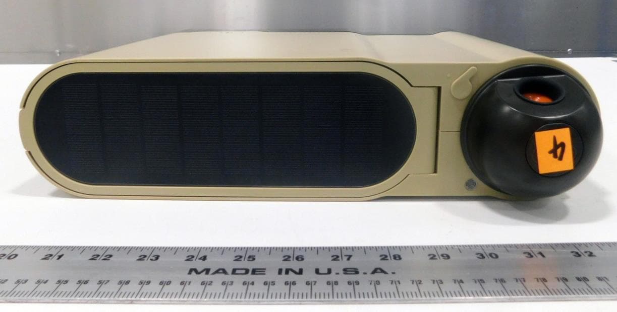
Click to zoom
Application Details
- Equipment Class
- DTS - Digital Transmission System
- Date of Grant
- Jun 07, 2022
- Application Purpose
- Original Equipment
- Date of Application
- Jun 07, 2022
- Equipment Note
- Smart Lawn Sprinkler
- Frequency Range
- 2422.00000000 - 2452.00000000
- Company
- OtO Inc.
- Country
- Canada
Documents & Files
Document Text
Text extracted from the exhibit documents filed with the FCC. Open a document above to read the original.
Users Manual
how to install. 1. Charge overnight by plugging your OtO into an outlet using the included Power Adapter (found inside the device). This ensures you are setting up with a full charge. 2. Download the OtO Lawn app from the Apple App Store® or Google Play® store. 3. Create an account. 4. Select Add New Device. 5. Place device in a spot that is well within range of 2.4 GHz Wi-Fi signal and receives a minimum of 3 hours per day of direct sunlight (if using the on-board solar panel). Do not install until Wi-Fi strength has been verified. 6. Turn the Switch. Select your OtO device from the list. 7. Connect to your home’s Wi-Fi network. Note: The OtO unit only works with 2.4 GHz Wi-Fi. If device does not connect, consider moving the router closer to the unit. 8. Device will connect and update firmware. This may take up to 5 minutes. If device does not connect, refer to the Troubleshooting section. 9. Name your device. 10. Choose to mount the device against a wall or in the ground. Hose and water pressure • With proper use, OtO typically reaches a maximum of 30 feet (9 m) with a minimum flow rate of 5.6 GPM. • Generally speaking, the best kind of hose to use is a high-quality 5/8” garden hose. • Use as short of a hose as possible to minimize pressure loss (max 50 feet ). • We recommend no more than two OtO units per water source. • We do not recommend flexi/expandable or light-duty garden hoses. CAUTION Pressurized hose may burst in high heat. Do not leave your hose pressurized and exposed to the sun. In order to keep your drinking water safe from contamination, the faucet that OtO will be connected to needs protection from the possibility of water flowing backward. Commonly known as a backflow device, government regulations specify what type of backflow device is required to adequately prevent water from flowing backward when a device such as OtO is connected to the water supply. Since the type of backflow device and maintenance schedule required by regulation varies at the city level, OtO is not responsible for damage or harm caused by not installing and maintaining the appropriate backflow device for your area. For more detail, visit support.otolawn.com. PATENT PENDING. FOR USE WITH COLD WATER ONLY. KEEP FROM FREEZING. getting started. For detailed installation instructions and videos, visit support.otolawn.com or use the QR code: To help with your OtO setup and coverage planning, try our online tool: otolawn.com/#lawnTool 1. Push the mounting bracket into the ground until the top is flush with surface. Use a blunt piece of wood as a mallet, if necessary. 2. Attach the four thumb screws to the device. 3. Push the device ‘feet’ into the bracket holes until all four are clicked into place. 1. Use the four included screws to secure the bracket into a wood fence. Note: Use appropriate hardware (not included) if installing into masonry. 2. Pass the threads on the 4 thumb screws through the mounting bracket holes and secure them to the device. Ground installationFence/wall installation 3h Pair Button LED Status Light LED Status Light Wake Switch Power Port 1 2 Wi-Fi signal strength • Make sure to pick a place within range of your network. Thick or insulated walls can greatly reduce Wi-Fi signal strength even if your router is close by. Test the Wi-Fi strength with the app before you mount and connect your device. • Device will only work on 2.4 GHz frequency. Sunlight and power • The on-board solar panel requires a minimum of 3 hours per day of direct, unobstructed sunlight. • If your device’s location does not receive enough sunlight, the provided cable and wall adapter can be used either permanently or as a power boost when needed. 3h Note: Device must be mounted or it will tip over when running. 11. Attach hose. 12. Turn on water completely. Make sure there are no leaks at any connection point. Create zones 13. From the app’s Device Overview page, tap the button. 14. The unit will begin to water. If no water comes out, confirm that the faucet is fully open and there are no kinks in the line. 15. Set the zone boundaries by tapping and releasing the arrow keys to move the water stream. Set Points to mark boundary edges. Tips: • When the unit achieves its max reach for the available pressure, a message will appear. If the distance is less than 30 feet, check the troubleshooting section. • Do not set points too close to each other – ensure points are at least 1 foot apart. • Press Remove Point to delete most recent point or Clear to start again. 16. Once finished, press Close to close the shape and then press Save. 17. Test your zone by tapping Demo Zone from the Settings menu. This performs a quick pass to show where the OtO unit will water. Actual cycles will complete multiple passes at different speeds when applying water. 18. Once you are happy with your zone, you can change the schedule and other options in the Zone Settings page. 19. Continue to add more zones as desired. otolawn.com Follow us on social media @OtOLawn day-to-day use. Maintenance – If your OtO device gets dirty, wipe down the outside with a damp cloth. Do not use abrasive chemicals. Keep the solar panel clean and unobstructed to ensure the battery stays fully charged. LED Status Light Lawn care, simplified. Copyright © 2021 OtO Lawn. All rights reserved. OtO and the OtO design are trademarks of OtO Inc. Information subject to change without notice. Oct 2021 0191-E. what’s in the box? • OtO Unit (1) • Mounting bracket (1) • Thumb screws (4) • Wood screws (4) • Power adapter with 50-ft cable (1) need help? For additional support at any time, contact us through the app by selecting Report Issues in the main menu. Website: support.otolawn.com Email: [email protected] troubleshooting. Can’t add new device (no status light) The battery may be depleted. Charge the device using the provided power adapter for a minimum of 24 hours. Can’t add new device Your device may be unable to see the OtO unit in your list of available Bluetooth devic…
Text truncated - open the document above for the full version.
Cover Letter(s)
OtO Inc. 150 Courtland Ave., Concord, ON Canada L4K 3T6 OtOLawn.com @OtOLawn 5/13/2022 Nemko Canada Inc. 303 River Road Ottawa, Ontario, Canada K1V 1H2 FCC ID: 2A6P5-6014F Model: OtO Lawn Request for Permanent Confidentiality Pursuant to Sections 0.457(d) and 0.459 of the Commission’s rules, we hereby request that the following documents be held confidential: Schematics Block diagram Bill of Materials Operation description These materials contain trade secrets and proprietary information and are not customarily released to the public. The public disclosure of this information might be harmful to the company and provide unjustified benefits to our competitors. Dated: 5/13/2022 Signed: Printed name: Greggory Johns Title: Director of Product and Engineering On behalf of: OtO Inc. DocuSign Envelope ID: 7972E634-2596-4AEF-AA02-98D73C25BEA0
Cover Letter(s)
OtO Inc. 150 Courtland Ave., Concord, ON Canada L4K 3T6 OtOLawn.com @OtOLawn Nemko Canada Inc 303 River Road Ottawa, Ontario, Canada K1V 1H2 Attn: Director of Certification Authority to Act as Agent FCC On our behalf, I appoint Spencer Zhong of Nemko Canada, Inc. 303 River Road, Ottawa, Ontario, Canada K1V 1H2, to act as our agent in the preparation of this application for equipment certification. I certify that submitted documents properly describe the device or system for which equipment certification is sought. I also certify that each unit manufactured, imported or marketed, as defined in FCC regulations will have affixed to it a label identical to that submitted for approval with this application. In signing this letter, Applicant certifies that neither the applicant nor any party to the application is not subject to a denial of Federal benefits, that include FCC benefits, pursuant to Section 5301 of the Anti-Drug Abuse Act of 1988, 21 U.S.C. § 862 because of a conviction for possession or distribution of a controlled substance. See 47 CFR 1.2002(b) for the definition of a "party" for these purposes. For instances where our authorized agent signs the application for certification on our behalf, I acknowledge that all responsibility for complying with the terms and conditions for certification, as specified by Nemko Canada Inc, still resides at OtO Inc. 150 Courtland Ave., Concord, ON, Canada, L4K3T6. Dated this 13 Day of May 20 22 Agency agreement expiration date: May 13, 2023 By: Greggory Johns Signature Printed Title: Director of Product and Engineering Telephone: 647-965-7792 On behalf of: OtO Inc. DocuSign Envelope ID: 7972E634-2596-4AEF-AA02-98D73C25BEA0
External Photos
OtO Inc. Model: OtO Lawn External photos
ID Label/Location Info
12 13 10 9 7 5 6 11 1 4 3 2 8 14 1 15 8 10 LID MUST CLOSE FLAT UNDER IT'S OWN WEIGHT, AND CANNOT BIND ON THE COVERS. 1.9±1 2 2 3 3 4 5 5 6 6 7 7 3 9 10 ASSEMBLY STEPCOMPONENTINSTRUCTION 1 LID ELECTRICAL CONNECTION ■PLUG IN THE CABLE FROM THE LID ASSEMBLY INTO THE TUBE LID ASSEMBLY, AND THEN INSTALL THE CABLE GROMMET ONTO THE TUBE LID ASSEMBLY ENSURING A LIQUID TIGHT FIT. ■PLACE THE ENCLOSER TENSIONER ASSEMBLY ON TOP OF THE LID SUPPORT PLATE AND ENSURE THE LID PLATE IS MAGNETIZED TO THE ENCLOSURE TENSIONER ASSEMBLY. 2 RESET BUTTON INSTALL MAGNETIC RESET BUTTON ASSEMBLY ALONG WITH A TORSION SPRING ONTO THE TUBE LID PLATE, AND CONFIRM BLUE LED FLASHES. 3 COVERS, LID ASSEMBLY ■REMOVE THE ENCLOSURE TENSIONER ASSEMBLY TEMPORARILY, AND INSTALL THE RIGHT SIDE COVER IN THE BASE AND TILT SLIGHTLY. ■INSTALL THE LID ASSEMBLY ONTO THE HINGE PIN OF THE RIGHT SIDE COVER ■INSTALL THE LEFT SIDE COVER INTO THE BASE, MATING THE CLIPS BETWEEN THE LEFT AND RIGHT SIDES, AND ENSURING THE LID ASSEMBLY STAYS ON THE HINGE PINS UNTIL THE COVERS ARE CLIPPED IN PLACE 4 ST2.9 x 9.5 SCREW ASSEMBLY INSTALL AND TIGHTEN THE TWO ST2.9 x 9.5 SCREWS THAT HOLD THE COVERS INTO THE TUBE LID ASSEMBLY, WHILE HOLDING THE FRONT PORTION OF THE TWO COVERS TOGETHER TO KEEP AN AESTHETIC GAP BETWEEN THE COVERS. TIGHTEN TO 1.1-1.25 N·m, USING AN ELECTRIC TORQUE LIMITING SCREWDRIVER SIMILAR TO THE MILWAUKEE 2101-20 M4, AT TORQUE SETTING #8 AND SPEED SETTING #1. 5 ENCLOSURE TENSIONER, ST2.9 x 9.5 SCREW ASSEMBLY INSTALL THE ENCLOSURE TENSIONER INTO THE ASSEMBLY, AND FASTEN THE ST2.9 x 9.5 BLACK THREAD FORMING SCREWS, STARTING WITH THE SCREWS CLOSEST TO THE NOZZLE WHILE HOLDING THE COVERS TOGETHER AT THE BUTTON LOCATION, THEN HOLDING AT THE LID OPENING END FOR THE REMAINING SCREWS. TIGHTEN TO 0.75-0.95 N·m, USING AN ELECTRIC TORQUE LIMITING SCREWDRIVER SIMILAR TO THE MILWAUKEE 2101-20 M4, AT TORQUE SETTING #5 AND SPEED SETTING #2. 6 DIFFUSER CAP AND TURN BUTTON ALIGN THE NOTCH AND PUSH THE LED DIFFUSER CAP INTO THE RIGHT COVER HOLE UNTIL IT CLICKS INTO PLACE, THEN PUSH THE TURN BUTTON INTO PLACE (LEG ALIGNED WITH LONG MARK ON THE COVER). 7 NOZZLE CHAMBER ASSEMBLY APPLY O-RING GREASE TO THE O-RING SURFACE OF THE NOZZLE BODY AND TO U- CUP SEAL CONTACT SURFACE, AND INSTALL THE NOZZLE CHAMBER ASSEMBLY INTO THE TUBE LID ASSEMBLY BY PUSHING DOWN UNTIL IT CLICKS IN PLACE. 8 AIR LEAK TEST AIR TEST THE FULL ASSEMBLY BY USING THE PLUG FIXTURE IN THE NOZZLE LID HOLES AND A CONNECTOR AT THE GARDEN HOSE CONNECTION, APPLY 14 TO 15 PSI AND SHUT OFF THE AIR, THEN WATCH FOR SEVERAL SECONDS TO ENSURE NO DECAY LEAKAGE OCCURS. 9 FUNCTION TEST RUN THE AUTOMATED END OF LINE TEST, WHICH INCLUDES TESTING OF EACH MOTOR, PUMP, POSITION AND PRESSURE SENSORS, AND SOLAR PANEL. IF THE TEST FAILS MARK THE UNIT AS REJECTED, OTHERWISE PUT THE JUST PRINTED LABEL UNDER THE LID. LABEL WILL NOT PRINT UNLESS THE UNIT PASSES. 10 CONTROLLER CABLE PLUG TUCK CONTROLLER CABLE INTO THE NOTCH IN THE RUBBER PLUG AND INSTALL RUBBER PLUG TO SEAL OFF MAIN TUBE COLUMN. REVCHGZONEDIM DATE YYYY-MM-DD DESCRIPTION OF CHANGEDRNCHKAPR E1------2022-05-07INITIAL RELEASEFVFV BILL OF MATERIALS ITEM PART NUMBER DESCRIPTIONQTY 16000-JOtO SKELETON ASSEMBLY1 26006-KLID SUBASSEMBLY1 36021-FMAGNET SLED SUBASSEMBLY1 40177-ABUTTON TORSION SPRING1 50089-NRIGHT SIDE COVER1 60090-MLEFT SIDE COVER1 76007-CENCLOSURE TENSIONER ASSEMBLY1 80013-AST2.9 x 9.5 THREAD FORMING STAINLESS SCREW2 90182-BST2.9 x 9.5 FLAT HEAD THREAD FORMING BLACK SCREW7 100215-ALED DIFFUSER CAP1 110219-ETURN BUTTON1 126004-JNOZZLE CHAMBER ASSEMBLY1 130218-BPOLYESTER LID LABEL1 140161-CRUBBER PLUG1 150004-ADUPONT MOLYKOTE 111 GREASE0.05 g 160258-AP-80 EMULSION IFC RUBBER LUBRICANT0.1 mL H G H G 1110912 1112910 63541728 F C B A E D F E D C 78563421 B A FRM-00377 / 1 REPRODUCTION AND/OR DISCLOSURE TO THIRD PARTIES WITHOUT PRIOR WRITTEN AUTHORIZATION BY OtO INCORPORATED IS STRICTLY PROHIBITED CONFIDENTIAL - ALL RIGHTS RESERVED PRODUCTION SHEET 11 OF SIZE A0 FILLETS AND RADIIDRAFT ANGLES FILE 6014-E1 STATUS CAD SYSTEM SOLIDWORKS 2022 OtO 2022 APPLICATION SCALEPROJECTION DO NOT SCALE 9:8 DRAWING NUMBER 6014-E TITLE 2022-05-07 YYYY-MM-DD PER ISO 8601 DATE APPROVED FV CHECKED DRAWN FV LAST DIM# -- 2743 TOTAL REF. PART MASS g OTHER = STAMPINGS = R2.0 LINEAR DIMENSIONS (mm) ANGULAR ( ) R1.5 2X MATL CASTINGS = GENERAL TOLERANCES & FEATURE DIMENSIONS UNLESS OTHERWISE SPECIFIED PRODUCTS TO COMPLY WITH CURRENT AND FUTURE SUBSTANCE OF CONCERN (SOC) REQUIREMENTS AND DIRECTIVES NO MANUAL CHANGES. BURRS, SHARP EDGES, CORROSION, DIRT OR FOREIGN MATERIALS (E.G., CHIPS, GREASE) DETRIMENTAL TO HANDLING, FUNCTION OR APPEARANCE ARE NOT PERMISSIBLE. ALL LINEAR DIMENSIONS ARE IN MILLIMETERS. PARTING LINE PROPOSED EJECTOR PIN LOCATION REFER TO INDICATED NOTE REVISION IDENTIFICATION DIMENSION IDENTIFICATION # SURFACE TEXTURE PER ISO 1302:2002 ISO 1101:2004 GEOMETRIC TOLERANCES PER GENERAL NOTES UNLESS OTHERWISE SPECIFIED OtO SPECIAL CHARACTERISTICS PER OtO CURRENT "GLOBAL SUPPLIER REQUIREMENTS AND GUIDELINES" MANUAL & OtO CURRENT "SPECIAL CHARACTERISTICS DESIGNATION" WORK INSTRUCTION OtO SPECIAL DRAWING SYMBOLS ASSEMBLED, UNPACKAGE OtO 2 / SIDE TOTAL ON DRAWING 0 = SIGNIFICANT = MAJOR = 100% INSPECTION = PASS THROUGH PTCM 100%M M S 0 0 0 ISO 8015 ISO 2768−mK TOLERANCES ACCORDING TO: CASTINGS: GENERAL TOLERANCES: OtO Incorporated
Internal Photos
www.nemko.com Internal photos.docx; Date: May 2013 Internal photos 464493-2RADWL Date of issue: June 3, 2022 Applicant: OtO Inc. Product name (PMN): OtO Lawn Model (HVIN): Product description: 6014-F Smart Lawn Sprinkler FCC ID: IC Registration number: 2A6P5-6014F 28550-6014F Section 1: Internal photos Report reference ID:464493RADWL2 Page 2 of 4 Section 1. Internal photos 1.1 Top general view Section 1: Internal photos Report reference ID:464493RADWL2 Page 3 of 4 1.2 RF module zoomed view Section 1: Internal photos Report reference ID:464493RADWL2 Page 4 of 4 1.3 PCB bottom view
RF Exposure Info
www.nemko.com Nemko Canada Inc., a testing laboratory, is accredited by the Standards Council of Canada. The tests included in this report are within the scope of this accreditation. The SCC Accreditation Symbol is an official symbol of the Standards Council of Canada, used under licence. SCC File Number: 15064 (Ottawa/Almonte); 151100 (Montreal); 151097 (Cambridge) FCC and RSS-102 Annex C – MPE Calculation; Date: May 2021 Choose Scandinavian trust RADIO TEST REPORT – 464493-1APFWL Type of assessment: MPE Calculation report Manufacturer: Hardware Version Identification Number (HVIN): OtO Inc. 6014-F Product Marketing Name (PMN): Product description: OtO Lawn Smart Lawn Sprinkler FCC ID: IC certification number: 2A6P5-6014F 28550-6014F Specification: FCC 47 CFR Part 1 Subpart I, §§1.1307, 1.1310 FCC 47 CFR Part 2 Subpart J, §2.1091 FCC KDB 447498 D01 General RF Exposure Guidance v06 ISED Canada RSS-102 Issue 5 Amendment 1, (February 2021) RSS-102 Annex B - Declaration of RF Exposure Compliance ATTESTATION: I attest that the information provided in Annex A is correct; that the Technical Brief was prepared and the information contained therein is correct; that the device evaluation was performed or supervised by me; that applicable measurement methods and evaluation methodologies have been followed; and that the device meets the SAR and/or RF field strength limits of RSS-102. Date of issue: June 8, 2022 Fahar Abdul Sukkoor, EMC/RF Specialist Prepared by Signature Report reference ID: 464493-1APFWL Page 2 of 6 Lab locations Company name Nemko Canada Inc. Facilities Ottawa site: 303 River Road Ottawa, Ontario Canada K1V 1H2 Tel: +1 613 737 9680 Fax: +1 613 737 9691 Montréal site: 292 Labrosse Avenue Pointe-Claire, Québec Canada H9R 5L8 Tel: +1 514 694 2684 Fax: +1 514 694 3528 Cambridge site: 1-130 Saltsman Drive Cambridge, Ontario Canada N3E 0B2 Tel: +1 519 650 4811 Almonte site: 1500 Peter Robinson Road West Carleton, Ontario Canada K0A 1L0 Tel: +1 613 256-9117 Test site identifier Organization Ottawa/Almonte Montreal Cambridge FCC: CA2040 CA2041 CA0101 ISED: 2040A-4 2040G-5 24676 Website www.nemko.com Limits of responsibility Note that the results contained in this report relate only to the items tested and were obtained in the period between the date of initial receipt of samples and the date of issue of the report. This test report has been completed in accordance with the requirements of ISO/IEC 17025. All results contained in this report are within Nemko Canada’s ISO/IEC 17025 accreditation. Copyright notification Nemko Canada Inc. authorizes the applicant to reproduce this report provided it is reproduced in its entirety and for use by the company’s employees only. Any use which a third party makes of this report, or any reliance on or decisions to be made based on it, are the responsibility of such third parties. Nemko Canada Inc. accepts no responsibility for damages, if any, suffered by any third party as a result of decisions made or actions based on this report. © Nemko Canada Inc. Report reference ID: 464493-1APFWL Page 3 of 6 Table of Contents Table of Contents ......................................................................................................................................................................................................... 3 Evaluation summary ........................................................................................................................................................................... 4 1.1 MPE calculation for simultaneous transmission ....................................................................................................................................................... 4 Section 1.2 MPE calculation for simultaneous transmission Report reference ID: 464493-1APFWL Page 4 of 6 Evaluation summary 1.1 MPE calculation for simultaneous transmission 1.1.1 References, definitions and limits FCC §2.1091(d) (2) (2) For operations within the frequency range of 300 kHz and 6 GHz (inclusive), the limits for maximum permissible exposure (MPE), derived from whole-body SAR limits and listed in Table 1 in paragraph (e)(1) of this section, may be used instead of whole-body SAR limits as set forth in paragraphs (a) through (c) of this section to evaluate the environmental impact of human exposure to RF radiation as specified in §1.1307(b) of this part, except for portable devices as defined in §2.1093 of this chapter as these evaluations shall be performed according to the SAR provisions in §2.1093. Table 1.1-1: Table 1 to §1.1310(e)(1)—Limits for Maximum Permissible Exposure (MPE) Frequency range (MHz) Electric field strength (V/m) Magnetic field strength (A/m) Power density (mW/cm 2 ) Averaging time (minutes) (i) Limits for Occupational/Controlled Exposure 0.3–3.0 614 1.63 *(100) ≤6 3.0–30 1842 / f 4.89 / f *(900 / f 2 ) <6 30–300 61.4 0.163 1.0 <6 300–1500 f / 300 <6 1500–100000 5 <6 (ii) Limits for General Population/Uncontrolled Exposure 0.3–1.34 614 1.63 *(100) <30 1.34–30 824 / f 2.19 / f *(180 / f 2 ) <30 30–300 27.5 0.073 0.2 <30 300–1500 f / 1500 <30 1500–100000 1.0 <30 Notes: f = frequency in MHz. * = Plane-wave equivalent power density. RSS-102, Section 2.5.2 RF exposure evaluation is required if the separation distance between the user and/or bystander and the device’s radiating element is greater than 20 cm, except when the device operates as follows: • below 20 MHz and the source-based, time-averaged maximum e.i.r.p. of the device is equal to or less than 1 W (adjusted for tune- up tolerance); • at or above 20 MHz and below 48 MHz and the source-based, time-averaged maximum e.i.r.p. of the device is equal to or less than 4.49/ƒ 0.5 W (adjusted for tune-up tolerance), where ƒ is in MHz; • at or above 48 MHz and below 300 MHz and the source-based, time-averaged maximum e.i.r.p. of the device is equal to or less than 0.6 W (adjusted for tune-up tolerance); • at or above 300 MHz and below 6 GHz and …
Text truncated - open the document above for the full version.
Test Report
www.nemko.com Nemko Canada Inc., a testing laboratory, is accredited by the Standards Council of Canada. The tests included in this report are within the scope of this accreditation. The SCC Accreditation Symbol is an official symbol of the Standards Council of Canada, used under licence. SCC File Number: 15064 (Ottawa/Almonte); 151100 (Montreal); 151097 (Cambridge) FCC 15.247, RSS-247 Issue 2; Date: March, 2020 Choose Scandinavian trust RADIO TEST REPORT – 464493-1TRFWL Type of assessment: Final product testing Applicant: Product name (PMN): OtO Inc. OtO Lawn Model (HVIN): Product description: 6014-F Smart Lawn Sprinkler FCC ID: IC Registration number: 2A6P5-6014F 28550-6014F Specifications: FCC 47 CFR Part 15 Subpart C, §15.247 RSS-247, Issue 2, Feb 2017, Section 5 Date of issue: June 3, 2022 Fahar Abdul Sukkoor, EMC/RF Specialist Tested by Signature Tarek Elkholy, EMC/RF Specialist Reviewed by Signature Report reference ID: 464493-1TRFWL Page 2 of 3 Lab locations Company name Nemko Canada Inc. Facilities Ottawa site: 303 River Road Ottawa, Ontario Canada K1V 1H2 Tel: +1 613 737 9680 Fax: +1 613 737 9691 Montréal site: 292 Labrosse Avenue Pointe-Claire, Québec Canada H9R 5L8 Tel: +1 514 694 2684 Fax: +1 514 694 3528 Cambridge site: 1-130 Saltsman Drive Cambridge, Ontario Canada N3E 0B2 Tel: +1 519 650 4811 Almonte site: 1500 Peter Robinson Road West Carleton, Ontario Canada K0A 1L0 Tel: +1 613 256-9117 Test site identifier Organization Ottawa/Almonte Montreal Cambridge FCC: CA2040 CA2041 CA0101 ISED: 2040A-4 2040G-5 24676 Website www.nemko.com Limits of responsibility Note that the results contained in this report relate only to the items tested and were obtained in the period between the date of initial receipt of samples and the date of issue of the report. This test report has been completed in accordance with the requirements of ISO/IEC 17025. All results contained in this report are within Nemko Canada’s ISO/IEC 17025 accreditation. Copyright notification Nemko Canada Inc. authorizes the applicant to reproduce this report provided it is reproduced in its entirety and for use by the company’s employees only. Any use which a third party makes of this report, or any reliance on or decisions to be made based on it, are the responsibility of such third parties. Nemko Canada Inc. accepts no responsibility for damages, if any, suffered by any third party as a result of decisions made or actions based on this report. © Nemko Canada Inc. Report reference ID: 464493-1TRFWL Page 3 of 4 Table of Contents Table of Contents ......................................................................................................................................................................................................... 3 Report summary ................................................................................................................................................................................. 4 1.1 Test specifications .................................................................................................................................................................................................... 4 1.2 Test methods ............................................................................................................................................................................................................ 4 1.3 Exclusions ................................................................................................................................................................................................................. 4 1.4 Statement of compliance .......................................................................................................................................................................................... 4 1.5 Test report revision history ....................................................................................................................................................................................... 4 Engineering considerations ................................................................................................................................................................. 5 2.1 Modifications incorporated in the EUT for compliance ............................................................................................................................................ 5 2.2 Technical judgment .................................................................................................................................................................................................. 5 2.3 Deviations from laboratory tests procedures ........................................................................................................................................................... 5 Test conditions ................................................................................................................................................................................... 6 3.1 Atmospheric conditions ............................................................................................................................................................................................ 6 3.2 Power supply range .................................................................................................................................................................................................. 6 Measurement uncertainty .................................................................................................................................................................. 7 4.1 Uncertainty of measurement ................................................................................................................................................................................... 7 Information provided by the applicant ...............................…
Text truncated - open the document above for the full version.
Test Report
www.nemko.com Nemko Canada Inc., a testing laboratory, is accredited by the Standards Council of Canada. The tests included in this report are within the scope of this accreditation. The SCC Accreditation Symbol is an official symbol of the Standards Council of Canada, used under licence. SCC File Number: 15064 (Ottawa/Almonte); 151100 (Montreal); 151097 (Cambridge) FCC 15.247, RSS-247 Issue 2; Date: March, 2020 Choose Scandinavian trust RADIO TEST REPORT – 464493-2TRFWL Type of assessment: Final product testing Applicant: Product name (PMN): OtO Inc. OtO Lawn Model (HVIN): Product description: 6014-F Smart Lawn Sprinkler FCC ID: IC Registration number: 2A6P5-6014F 28550-6014F Specifications: FCC 47 CFR Part 15 Subpart C, §15.247 RSS-247, Issue 2, Feb 2017, Section 5 Date of issue: June 3, 2022 Fahar Abdul Sukkoor, EMC/RF Specialist Tested by Signature Tarek Elkholy, EMC/RF Specialist Reviewed by Signature Report reference ID: 464493-2TRFWL Page 2 of 59 Lab locations Company name Nemko Canada Inc. Facilities Ottawa site: 303 River Road Ottawa, Ontario Canada K1V 1H2 Tel: +1 613 737 9680 Fax: +1 613 737 9691 Montréal site: 292 Labrosse Avenue Pointe-Claire, Québec Canada H9R 5L8 Tel: +1 514 694 2684 Fax: +1 514 694 3528 Cambridge site: 1-130 Saltsman Drive Cambridge, Ontario Canada N3E 0B2 Tel: +1 519 650 4811 Almonte site: 1500 Peter Robinson Road West Carleton, Ontario Canada K0A 1L0 Tel: +1 613 256-9117 Test site identifier Organization Ottawa/Almonte Montreal Cambridge FCC: CA2040 CA2041 CA0101 ISED: 2040A-4 2040G-5 24676 Website www.nemko.com Limits of responsibility Note that the results contained in this report relate only to the items tested and were obtained in the period between the date of initial receipt of samples and the date of issue of the report. This test report has been completed in accordance with the requirements of ISO/IEC 17025. All results contained in this report are within Nemko Canada’s ISO/IEC 17025 accreditation. Copyright notification Nemko Canada Inc. authorizes the applicant to reproduce this report provided it is reproduced in its entirety and for use by the company’s employees only. Any use which a third party makes of this report, or any reliance on or decisions to be made based on it, are the responsibility of such third parties. Nemko Canada Inc. accepts no responsibility for damages, if any, suffered by any third party as a result of decisions made or actions based on this report. © Nemko Canada Inc. Report reference ID: 464493-2TRFWL Page 3 of 59 Table of Contents Table of Contents ......................................................................................................................................................................................................... 3 Report summary ................................................................................................................................................................................. 4 1.1 Test specifications .................................................................................................................................................................................................... 4 1.2 Test methods ............................................................................................................................................................................................................ 4 1.3 Exclusions ..................................................…
Text truncated - open the document above for the full version.
Contact Information
Applicant
Greggory Johns(Director of Product and Engineering)
Test Firm
Nemko Canada Inc. (Cambridge)Charles Neal
[email protected]613-737-9680
Technical Specifications
| # | Rule Parts | Frequency Range | Power Output |
|---|---|---|---|
| 3 | 15C | 2.42 GHz - 2.45 GHz | 11.20 mW |