2A6RS-R102Thrive Receiver
Thrive Smart Systems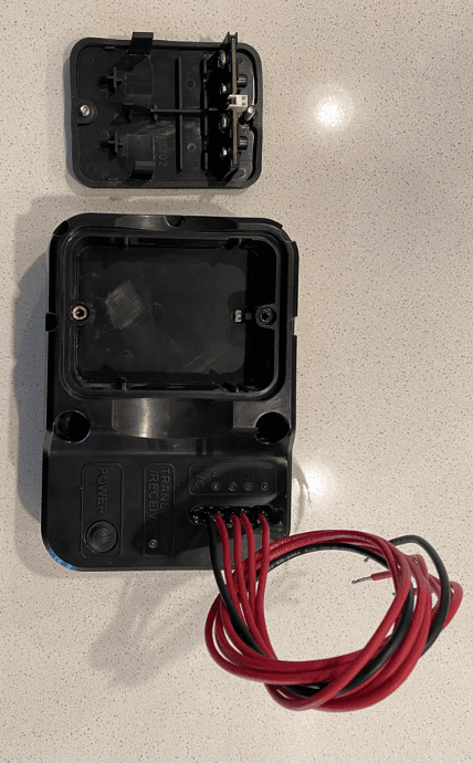
Click to zoom
Application Details
- Equipment Class
- DTS - Digital Transmission System
- Date of Grant
- Jun 02, 2022
- Application Purpose
- Original Equipment
- Date of Application
- Jun 01, 2022
- Equipment Note
- Thrive Receiver
- Frequency Range
- 903.50000000 - 925.30000000
- Company
- Thrive Smart Systems
- Country
- United States
Documents & Files
Document Text
Text extracted from the exhibit documents filed with the FCC. Open a document above to read the original.
Users Manual
Wireless Valve EVO TM Installation & User Manual Rev 19.0 Thrive Smart Systems Inc. (980) 202-2504 www.thrivesmartsystems.com TM Thrive EVO TM Installation and User Manual Table of Contents Introduction _________________________________________________________________________________ 1 Key Product Features __________________________________________________________________________ 1 How Does it Work? ___________________________________________________________________________ 2 Verify Contents of Packaging ___________________________________________________________________ 3 Recommended Tools __________________________________________________________________________ 4 Getting Started ______________________________________________________________________________ 5 Summary of Installation _______________________________________________________________________ 5 Installation __________________________________________________________________________________ 6 Thrive Transmitter TM _______________________________________________________________________ 6 Step 1 – Installing the transmitter _____________________________________________________________ 6 Step 2 – Field Wire Connections ______________________________________________________________ 7 Option #1 – Use Irrigation Controller’s 24-volt Auxiliary Power Output ______________________________ 7 Option 2 – Install an External Transformer Exclusively for the Transmitter TM _________________________ 8 Thrive Receiver TM __________________________________________________________________________ 9 Step 1 – Install the Pair of 9-volt Batteries ______________________________________________________ 9 Step 2 – Install DC Latching Solenoids _________________________________________________________ 10 Step 3 – Make Wire Connections to Valve(s) ___________________________________________________ 10 Step 4 – Press the Power Button to the receiver “On”. ___________________________________________ 11 Step 5 – Secure the receiver to the Underside of a Valve Box Lid. ___________________________________ 11 Warning Labels _____________________________________________________________________________ 12 Operating the EVO TM System __________________________________________________________________ 12 Thrive Transmitter TM States ___________________________________________________________________ 12 Replacing Thrive Receiver TM Batteries ___________________________________________________________ 14 Troubleshooting_____________________________________________________________________________ 15 Product Warranty ___________________________________________________________________________ 16 Product Limitations __________________________________________________________________________ 17 FCC Compliance Notice _______________________________________________________________________ 17 Electrical Specifications _______________________________________________________________________ 18 Thrive Transmitter TM ______________________________________________________________________ 18 Thrive Receiver TM _________________________________________________________________________ 18 Mechanical Specifications _____________________________________________________________________ 18 Thrive Transmitter TM ______________________________________________________________________ 18 Thrive Receiver TM _________________________________________________________________________ 18 Enclosure Specifications ____________________________________________________________________ 18 Thrive EVO TM Installation and User Manual Antenna Specifications _____________________________________________________________________ 18 Radio Information_________________________________________________________________________ 19 Replacement Parts___________________________________________________________________________ 19 Index ______________________________________________________________________________________ 21 Thrive EVO TM Installation and User Manual 1 Introduction Welcome to the future of wireless irrigation communication: Thrive Smart System’s EVO TM , today’s solution for overcoming broken or lost field wire and easily adding new valves. The EVO TM is comprised of two, fully pre-paired components, the Thrive Transmitter TM and Thrive Receiver TM . They provide up to 200 yards range of consistent and reliable two-way wireless communication and are compatible with most multi-wire irrigation controllers. We believe you’ll find this product easy-to-use and easy-to-install, all while providing reliable and consistent operation for years to come. Key Product Features The Thrive Smart System EVO TM : • Is comprised of a Thrive Transmitter TM and a Thrive Receiver TM that are pre-paired to the same radio frequency for ease of installation. The Thrive Transmitter TM receives power via a 24VAC, and is contained in a key-lock entry, weather-resistant enclosure. • The Thrive Receiver TM has several gaskets to maintain a waterproof case up to a depth of 1.2 meters and is IP67 rated. • The Receiver TM is powered by two, 9-volt lithium batteries located in a battery cassette making it easy to remove and replace batteries when needed. The Receiver will also operate on 2, 9-volt Alkali batteries, but with a much shorter service life. • Provides reliable and consistent wireless communication up to 200 yards. • Includes unique paired frequencies that eliminate interference when other Thrive EVO’s TM are used on the same or adjacent sites. • Manages up to four individual remote-control valves per Transmitter. If additional valves are needed, then another EVO TM is required. • Manages up to four valves with DC Latching solenoids at one time if the control system has this capability. • Displays real-time remaining battery life and signal strength on the Thrive Transmitter TM . • Has a built-in fail-safe to turn off any operating valves in the event that AC power is lost. • This is an FCC compliant product that does not requi…
Text truncated - open the document above for the full version.
External Photos
Thrive Smart Systems Inc. 980 Queens Dr. • American Fork, UT 84003 385•225•5801 www.thrivesmartsystems.com 1100202 FCC ID: 2A6RS – R102 External Photos Front Bottom Side Top Side Left Side Right Side Battery Compartment
ID Label/Location Info
Thrive Smart Systems Inc. 980 Queens Dr. • American Fork, UT 84003 385•225•5801 www.thrivesmartsystems.com 1100202 FCC ID: 2A6RS – R102 ID Label/Location Info The ID label is located inside the battery compartment. The chamber is IP67 rated. There is an additional identical label that is placed over the shield on the PCBA. Both of these labels are waterproof and have permanent adhesive.
Internal Photos
Thrive Smart Systems Inc. 980 Queens Dr. • American Fork, UT 84003 385•225•5801 www.thrivesmartsystems.com 1100202 FCC ID: 2A6RS – R102 Internal Photos
RF Exposure Info
Certificates and reports shall not be reproduced except in full, without the written permission of H.B Compliance Solutions, LLC. Maximum Permissible Exposure Statement For the Thrive Smart Systems Receiver May 31, 2022 Prepared for: Thrive Smart Systems 980 Queens Drive American Fork, Utah 84003 Prepared By: H.B. Compliance Solutions 5005 S. Ash Avenue, Suite # A-10 Tempe, Arizona 85282 Reviewed By: Hoosamuddin Bandukwala Cert # ATL-0062-E HBCS MPE Report # EMC_22013_1 Rev1 Page 2 of 2 Prediction of MPE limit at a given distance Equation from page 18 of OET Bulletin 65, Edition 97-01 S = PG/4πR2 Where, S = power density (mW/cm2) P = output power at the antenna terminal (mW) G = gain of transmit antenna (numeric) R = distance from transmitting antenna (cm) For LoRa Transmitter Maximum peak output power at antenna input terminal = 18.30 (dBm) * Maximum peak output power at antenna input terminal = 67.60(mW) Antenna gain (typical) = 1.5(dBi) Maximum antenna gain = 1.41 (numeric) Prediction distance = 20 (cm) Prediction frequency = 903.5 (MHz) MPE limit for uncontrolled exposure at prediction frequency = 0.6 (mW/cm^2) Power density at prediction frequency = 0.0189 (mW/cm^2) *Includes 1dB of manufacturer output power tolerance. To solve for the minimum mounting distance required; R = √ (PG/4πS) R = √ (67.6 x 1.41 / 4π x 0.0189) = 20 cm (Based on continuous transmission) END OF TEST REPORT
Test Report
Certificates and reports shall not be reproduced except in full, without the written permission of H.B Compliance Solutions, LLC. Intentional Radiator Test Report For the Thrive Smart Systems EVO Wireless Valve System Receiver Tested under The FCC Rules contained in Title 47 of the CFR, Part 15.247 Digital Transmission Systems Prepared for: Thrive Smart Systems 980 Queens Drive American Fork, UT 84003 Prepared By: H.B. Compliance Solutions 5005 S. Ash Avenue, Suite # A-10 Tempe, Arizona 85282 Reviewed By: Hoosamuddin Bandukwala Cert # ATL-0062-E Engineering Statement: The measurements shown in this report were made in accordance with the procedure indicated, and the emissions from this equipment were found to be within the limits applicable. I assume full responsibility for the accuracy and completeness of these measurements, and for the qualifications of all persons taking them. It is further stated that upon the basis of the measurement made, the equipment tested is capable of operation in accordance with the requirements of Part 15 of the FCC Rules under normal use and maintenance. All results contained herein relate only to the sample tested. HBCS Report # RF_22013_1 Rev_1 Page 2 of 35 Report Status Sheet Revision # Report Date Reason for Revision Ø May 16, 2022 Initial Issue 1 May 28, 2022 Added Plots with Average Power using Integration Method. HBCS Report # RF_22013_1 Rev_1 Page 3 of 35 Table of Contents EXECUTIVE SUMMARY ............................................................................................ 4 1. Testing Summary ........................................................................................ 4 EQUIPMENT CONFIGURATION ................................................................................ 5 1. Overview .................................................................................................... 5 2. Test Facility ................................................................................................. 6 3. Description of Test Sample ......................................................................... 7 4. Equipment Configuration ........................................................................... 7 5. Support Equipment .................................................................................... 7 6. Ports and Cabling Information .................................................................... 7 7. Method of Monitoring EUT Operation ........................................................ 7 8. Mode of Operation ..................................................................................... 8 9. Modifications ............................................................................................. 8 10. Disposition of EUT ...................................................................................... 8 Criteria for Un-Intentional Radiators ...................................................................... 9 1. Radiated Emissions ..................................................................................... 9 Emissions Tests Calculations ...................................................................... 10 Criteria for Intentional Radiators .......................................................................... 12 1. Occupied Bandwidth ................................................................................ 12 2. RF Power Output ...................................................................................... 16 3. Conducted Spurious Emissions ................................................................. 19 4. Radiated Spurious Emissions and Restricted Band ................................... 26 6. Emissions At Band Edges .......................................................................... 29 7. Power Spectral Density ............................................................................. 31 8. Test Equipment ............................................................................................. 34 9. Measurement Uncertainty ............................................................................ 35 HBCS Report # RF_22013_1 Rev_1 Page 4 of 35 EXECUTIVE SUMMARY 1. Testing Summary These tests were conducted on a sample of the equipment for the purpose of demonstrating compliance with Part 15.247. All tests were conducted using measurement procedure from ANSI C63.10-2013, and FCC Guidance document 558074 D01 v05r02 April 02, 2019. Test Name Test Method/Standard Result Comments Unintentional Radiated Emissions 15.109 Pass A/C Powerline Conducted Emissions 15.207 N/A Battery Powered Occupied Bandwidth 15.247(a)(2) Pass Peak Output Power 15.247(b) Pass Conducted Spurious Emissions 15.247(d) Pass Radiated Spurious Emissions & Restricted Band 15.247(d), 15.209(a), 15.205 Pass Emissions at Band Edges 15.247(d), 15.209(a), 15.205 Pass Power Spectral Density 15.247(e) Pass Time of Occupancy (Dwell Time) 15.247(a) N/A Number of Hopping Channels 15.247(a) N/A Carrier Frequency Separation 15.247(a) N/A HBCS Report # RF_22013_1 Rev_1 Page 5 of 35 EQUIPMENT CONFIGURATION 1. Overview H.B Compliance Solutions was contracted by Thrive Smart Systems to perform testing on the EVO Wireless Valve System under the purchase order number HB001. This document describes the test setups, test methods, required test equipment, and the test limit criteria used to perform compliance testing of the Thrive Smart Systems, EVO Wireless Valve System. The tests were based on FCC Part 15 Rules. The tests described in this document were formal tests as described with the objective of the testing was to evaluate compliance of the Equipment Under Test (EUT) to the requirements of the aforementioned specifications. Thrive Smart Systems should retain a copy of this document and it should be kept on file for at least five years after the manufacturing of the EUT has been permanently discontinued. The results obtained relate only to the item(s) tested. Product Name: EVO Wireless V…
Text truncated - open the document above for the full version.
Test Setup Photos
1 | Page Test Setup Photos Thrive Systems – Project 22013 - Receiver Test Setup Photo # 1 Test Setup Photo # 2 2 | Page Test Setup Photo # 3 Test Setup Photo # 4
Contact Information
Applicant
Skyler Rowley
Test Firm
H.B. Compliance SolutionsHoosamuddin Bandukwala
[email protected]480-684-2969
Technical Specifications
| # | Rule Parts | Frequency Range | Power Output |
|---|---|---|---|
| 1 | 15C | 903.5 MHz - 925.3 MHz | 67.00 mW |