2A6WL-PCLR1People Counter LoRaWAN (IR RX)
IMBuildings B.V.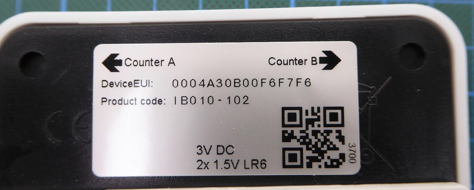
Click to zoom
Application Details
- Equipment Class
- JAB - Part 15 Class B Digital Device
- Date of Grant
- Jan 17, 2023
- Application Purpose
- Original Equipment
- Date of Application
- Jan 17, 2023
- Equipment Note
- People Counter LoRaWAN (IR RX)
- Company
- IMBuildings B.V.
- Country
- Netherlands
Documents & Files
Document Text
Text extracted from the exhibit documents filed with the FCC. Open a document above to read the original.
Users Manual
Manual People Counter LoRaWAN IMBuildings B.V. 2022 v1.5 Preface Note: This equipment has been tested and found to comply with the limits for a Class B digital device, pursuant to part 15 of the FCC Rules. These limits are designed to provide reasonable protection against harmful interference in a residential installation. This equipment generates, uses and can radiate radio frequency energy and, if not installed and used in accordance with the instructions, may cause harmful interference to radio communications. However, there is no guarantee that interference will not occur in a particular installation. If this equipment does cause harmful interference to radio or television reception, which can be determined by turning the equipment off and on, the user is encouraged to try to correct the interference by one or more of the following measures: -Reorient or relocate the receiving antenna. -Increase the separation between the equipment and receiver. -Connect the equipment into an outlet on a circuit different from that to which the receiver is connected. -Consult the dealer or an experienced radio/TV technician for help. This device complies with part 15 of the FCC Rules. Operation is subject to the following two conditions: (1) This device may not cause harmful interference, and (2) this device must accept any interference received, including interference that may cause undesired operation. Changes or modifications not expressly approved by the party responsible for compliance could void the user’s authority to operate the equipment. 1 Read,follow, and keep these instructions 1.Heed all warnings 2.Only use attachments/accessories specified by the manufacturer ! WARNING:To reduce the risk of fire and/or electric shock,do not expose this product to rain or moisture. ! WARNING: Do not use this product in a location that can be submerged in water. Battery Warning(If applicable) 1.Do not expose cells or batteries to heat or fire. Avoid storage in direct sunlight. 2.Purchase batteries recommended by the manufacturer. 3.The manufacturer’s instructions for the respective batteries need to be observed. Electrical Safety Information(if applicable) There are no operator serviceable components in this device, service and repair should always be done by qualified professionals Radiation Exposure Statement To comply with the FCC RF Exposure requirements for an uncontrolled environment, the IR Receiver with the integrated LoRaWAN transceiver must be installed and operated with a minimum separation distance of at least 20 cm to any human person during normal operating conditions. Operating frequency Max. RF Output Power : 902.3 - 927.5 MHz (for FCC) : 81 mW (for FCC) 2 Index Preface1 Index2 Safety instructions4 1. Product introduction5 1.2 Principle of work5 1.3 Communication5 1.4 Specifications5 2. Configurable settings7 3. Contents of delivery9 4. Installation Tools9 5. Accessories10 6. Installation12 6.1 Handling the housing12 6.2 Count directions14 6.3 Mount the People Counter14 6.4 Additional information15 6.5 ENI (Enhanced Noise Immunity)15 7. Power on16 7.1 IR Transmitter16 7.2 IR Receiver17 7.2.1 Power On:17 7.2.2 Validation mode18 7.2.3 Counting mode18 7.3 Alignment mode18 7.4 Accuracy of the People Counter18 8. Ordering information19 8.1 People Counter sets19 8.2 People Counter parts19 8.3 Accessories19 Caring for the environment by recycling.20 3 Disclaimer20 Notes21 4 Safety instructions To avoid damage or malfunction, please take the following into consideration. ●Do not expose to water,moisture,and conductive surfaces. ●Do not expose to heat from any source, the product is designed to work under normal ambient temperatures. ●Take care when handling the device,to prevent damage to the mechanical or electrical components. ●Avoid handling the circuit board while the device is powered, to minimize the chance of electrostatic damage. Ambient operating temperature 0-40°C at 0-95% non condensing humidity. Nominal Voltage3V Power supply2x AA 1.5V batteries* Maximum power consumption 60mA *The manufacturer's instructions for the respective batteries need to be observed The capabilities,system requirements and / or compatibility with third party products described herein are subject to change without notice. 5 1. Product introduction The LoRaWAN People Counter is a battery powered sensor for counting people crossing a horizontal line. The counter consists of two parts, an infrared (IR) transmitter part and an infrared receiver part, which always work together. The IR transmitter the infrared signal. The IR receiver is the main part and holds the intelligence and communication with the outside world. 1.2 Principle of work The IR transmitter device points the IR beam horizontal towards the IR receiver part at a recommended height. When this beam is interrupted, the algorithm in the IR receiver part determines if this was a person and determines the direction A or B. 1.3 Communication The created data is communicated from the internal algorithm microprocessor to the internal gateway microprocessor. The internal gateway processor communicates this information to the internal LoRaWAN (Certified) module which takes care of the communication with the LoRaWAN network. Settings for the LoRaWAN interface are done via NFC memory. 1.4 Specifications For main technical specification please refer theproduct sheet. Technical specifications Single operation voltageNominal 3.0V Power supply2x AA Batteries Protection degreeIP20 6 Image: IR Receiver part Image: IR Transmitter part *batteries shown in the picture are not included. a black sliding bracket on the back side may also be used 7 2. Configurable settings The table below shows the settings which can be configured using the NFC Memory. Table 1: SettingInfoDefault Value EU868 Send interval1 to 240 minutes15 minutes Device registrationABP or OTAAOTAA ABP App Session Key128 bits keyBlank ABP Network Session Key128 bits keyBlank ABP Device Address4 bytes addressBl…
Text truncated - open the document above for the full version.
Cover Letter(s)
Long/Short-term Confidentiality Request PHOENIX TESTLAB GmbH Date: 17 January 2023 Product Certification Königswinkel 10 D 32825 Blomberg FCC ID: 2A6WL-PCLR1 To Whom It May Concerns, Pursuant to sections 0.457(d) and 0.459 of CFR 47 and to avoid premature release of sensitive information prior to marketing or release of the product to the public, we hereby request long-term confidential treatment of information accompanying this application as outlined below: ☒ Schematics ☐ Parts List ☒ Block Diagram ☐ Tune-Up Info ☐ Operational Description In addition, we hereby request the following exhibits contained in this application to be temporarily (short-term confidentiality) withheld from the public disclosure ☐ for an initial period of days ☐ until: ☒ not applicable ☐ External Photos ☐ Test Setup Photos ☐ Internal Photos ☐ Users Manual The above materials contain trade secrets and proprietary information not customarily released to the public. The public disclosure of these matters might be harmful to the applicant and provide unjustified benefits to its competitors. The applicant understands that pursuant to rule 0.457(d), disclosure of this application and all accompanying documentation will not be made before the date of the GRANT for this application. If you have any questions, please feel free to contact me. Yours sincerely, Sabrina Berghahn Authorized Agent
Cover Letter(s)
PHOENIX TESTLAB GmbH Product Certification Department Koenigswinkel 10 32825 Blomberg, Germany Power of Attorney To Whom It May Concern: Please be advised that we, IMBuildings, authorize the following persons from PHOENIX TESTLAB GmbH: Sabrina Berghahn to act on our behalf in all matters relating to application for equipment authorization, including the signing of all documents relating to these matters in the following countries: USA PHOENIX TESTLAB GmbH has our permission to use our technical documents for the approvals for the following name device: People Counter - LoRaWAN FCC ID: 2A6WL-PCLR1 Unless future correspondence from IMBuildings BV please extend your full cooperation to PHOENIX TESTLAB GmbH regarding matters to the above mentioned products to 12 months after the signatory date of this authorization. Contact personR.F.Meijerink Position in the companyDirector Date of signatory06-09-22 __________________________ Signatory (signature of the applicant)
External Photos
External Photographs Examiner:Bernward ROHDERevision:00 Date of issue: 16.01.2023Order Number: 21-111971page 1 of 3 EUT (IR receiver with LoRaWAN) Top view External Photographs Examiner:Bernward ROHDERevision:00 Date of issue: 16.01.2023Order Number: 21-111971page 2 of 3 EUTs Bottom view External Photographs Examiner:Bernward ROHDERevision:00 Date of issue: 16.01.2023Order Number: 21-111971page 3 of 3 IR receiver
ID Label/Location Info
Label information Label on IR Receiver part / part which contains RF. FCC LABEL LOCATION The label will be permanently affixed at a conspicuous location on the device FCC ID: 2A6WLPCLR1 FCC ID Label Area for mounting using double sided tape FCC ID Label Box v2 Box v1 Removable sliding bracket
Internal Photos
Internal Photographs Examiner:Bernward ROHDERevision:00 Date of issue: 16.01.2023Order Number: 21-111971page 1 of 5 1.1 IR receiver Receiver opened Internal Photographs Examiner:Bernward ROHDERevision:00 Date of issue: 16.01.2023Order Number: 21-111971page 2 of 5 Receiver PCB Top view1 Internal Photographs Examiner:Bernward ROHDERevision:00 Date of issue: 16.01.2023Order Number: 21-111971page 3 of 5 Receiver PCB Top view2 Integrated LoRA-WAN not yet finally labelled Internal Photographs Examiner:Bernward ROHDERevision:00 Date of issue: 16.01.2023Order Number: 21-111971page 4 of 5 Radio part Detail view Internal Photographs Examiner:Bernward ROHDERevision:00 Date of issue: 16.01.2023Order Number: 21-111971page 5 of 5 Receiver PCB Bottom view
Operational Description
1. Product introduction The LoRaWAN People Counter is a battery powered sensor for counting people crossing a horizontal line. The counter consists of two parts, an infrared (ir) transmitter part and an infrared receiver part, which always work together. The ir-transmitter creates an intermediate infrared signal in a fixed frequency. The ir-receiver is the main part and holds the intelligence and communication with the outside world. 1.1 Principle of work • • • The ir-transmitter device points the ir beam horizontal towards the ir-receiver part at a recommended height. When this beam is interrupted, the algorithm in the ir-receiver part determines if this was a person and determines the direction A or B. 1.2 Communication • The created data is communicated from the internal algorithm microprocessor to the internal gateway microprocessor. The internal gateway processor communicates this information to the internal LoRaWAN (Certified) module* which takes care of the communication with the LoRaWAN network. Settings for the LoRaWAN interface are done via NFC memory. • Please refer the Related information chapter for more details about this module 1.3 Specifications For main technical specification please refer the product sheet. Technical specifications Single operation voltage Nominal 3.0V Power supply 2x AA Batteries Protection degree IP20 II ------- -------- - ===· ::-...:... --·-·----= -·- =.. - _____.. _ , ____ ,_. ___ _ , _____ _ Productsheet Copyright IMBUILDINGS 2019 v1.1 People Counter LoRaWAN
Test Report
Königswinkel 10 32825 Blomberg, Germany Phone: +49 (0) 52 35 / 95 00-0 Fax: +49 (0) 52 35 / 95 00-10 [email protected] www.phoenix-testlab.de Test Report Report Number: F211971E1 Equipment under Test (EUT): People Counter LoRaWAN (IR Receiver) People Counter LoRaWAN (IR Transmitter) Applicant: IMBuildings B.V. Manufacturer: IMBuildings B.V. Examiner: Bernward ROHDE Report Number: F211971E1 Date of Issue: 16.01.2023 Order Number: 21-111971 Page 2 of 19 References [1] ANSI C63.4:2014 American National Standard for Methods of Measuring of Radio-Noise Emissions from Low-Voltage Electrical and Electronic Equipment in the Range of 9 kHz to 40 GHz. [2] FCC 47 CFR Part 2: General Rules and Regulations [3] FCC 47 CFR Part 15: Radio Frequency Devices (Subpart B) [4] ICES-003 Issue 7: (October 2020) Spectrum Management and Telecommunications. Interference-Causing Equipment Standard. Information Technology Equipment (Including Digital Apparatus) —Limits and Methods of Measurement Examiner: Bernward ROHDE Report Number: F211971E1 Date of Issue: 16.01.2023 Order Number: 21-111971 Page 3 of 19 Test Result The requirements of the tests performed as shown in the overview (clause 4) were fulfilled by the equipment under test. The complete test results are presented in the following. “Passed” indicates that the equipment under test conforms with the relevant limits of the testing standard without taking any measurement uncertainty into account as stated in clause 10.2.8.2 of ANSI C63.4 (2014). However, the measurement uncertainty is calculated and shown in this test report. T h i s t e s t r e p o r t i s o n l y v a l i d i n i t s o r i g i n a l f o r m. Any reproduction of its contents in extracts without written permission of the accredited test laboratory PHOENIX TESTLAB GmbH is prohibited. The test results herein refer only to the tested sample. PHOENIX TESTLAB GmbH is not responsible for any generalisations or conclusions drawn from these test results concerning further samples. Any modification of the tested samples is prohibited and leads to the invalidity of this test report. Each page necessarily contains the PHOENIX TESTLAB Logo and the TEST REPORT NUMBER. Tested and written by: Signature Reviewed and approved by: Signature Examiner: Bernward ROHDE Report Number: F211971E1 Date of Issue: 16.01.2023 Order Number: 21-111971 Page 4 of 19 Contents: Page Identification ................................................................................................................................. 5 1.1 Applicant ................................................................................................................................................... 5 1.2 Manufacturer ............................................................................................................................................ 5 1.3 Test Laboratory ........................................................................................................................................ 5 1.4 EUT (Equipment under Test) ................................................................................................................... 6 1.4.1 IR receiver ....................................................................................................................................... 6 1.4.2 IR transmitter ................................................................................................................................... 6 1.5 Technical Data of Equipment ................................................................................................................... 7 1.5.2 IR receiver ....................................................................................................................................... 7 1.6 Dates ........................................................................................................................................................ 8 Operational States ........................................................................................................................ 8 Additional Information ................................................................................................................... 9 Overview ....................................................................................................................................... 9 Results........................................................................................................................................ 10 5.1 Test setups ............................................................................................................................................. 10 5.1.1 Radiated: 30 MHz to 1 GHz ........................................................................................................... 10 5.1.2 Radiated: 1 GHz to 40 GHz ........................................................................................................... 12 5.2 Radiated emissions ................................................................................................................................ 14 5.2.1 Test setup (Maximum unwanted emissions) ................................................................................. 14 5.2.2 Test method (Maximum unwanted emissions) .............................................................................. 14 5.2.3 Test results (Maximum unwanted emissions) ............................................................................... 14 Measurement Uncertainties ........................................................................................................ 18 Test Equipment used for Tests ................................................................................................... 18 Test site Verification .................................................................................................................... 19 Report History ..................................................…
Text truncated - open the document above for the full version.
Test Setup Photos
Annex A Test Setup Photos Examiner:Bernward ROHDEReport Number: F211971E1 Date of issue: 16.01.2023Order Number: 21-111971page 1 of 5 Test Setup Photos Semi Anechoic Chamber Test setup semi anechoic chamber Table setup (Pos 1) Annex A Test Setup Photos Examiner:Bernward ROHDEReport Number: F211971E1 Date of issue: 16.01.2023Order Number: 21-111971page 2 of 5 Test setup semi anechoic chamber 30 MHz - 1 GHz Annex A Test Setup Photos Examiner:Bernward ROHDEReport Number: F211971E1 Date of issue: 16.01.2023Order Number: 21-111971page 3 of 5 Test setup semi anechoic chamber with ground absorbers 1 GHz – 10 GHz Annex A Test Setup Photos Examiner:Bernward ROHDEReport Number: F211971E1 Date of issue: 16.01.2023Order Number: 21-111971page 4 of 5 Equipment used for testing Laird Gateway Annex A Test Setup Photos Examiner:Bernward ROHDEReport Number: F211971E1 Date of issue: 16.01.2023Order Number: 21-111971page 5 of 5 “Windmill” with provided power supply
Contact Information
Applicant
Remko Meijerink
Test Firm
PHOENIX TESTLAB GmbHHolger Bentje
Technical Specifications
| # | Rule Parts | Frequency Range | Power Output |
|---|---|---|---|
| 1 | 15B | - | - |
Other Applications from IMBuildings B.V.
2A6WL-OOCLR3
Mar 04, 2026VertiCount Pro
Equipment Class
JAB - Part 15 Class B Digital Device
2A6WLPCTX1
Jan 17, 2023People Counter LoRaWAN (IR TX)
Equipment Class
JAB - Part 15 Class B Digital Device