2A754-AT01Researcher Ring
Senstream, Inc.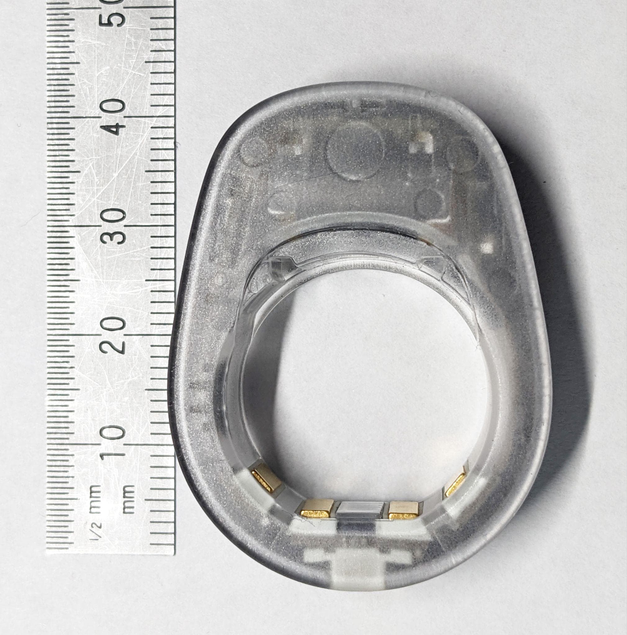
Click to zoom
Application Details
- Equipment Class
- DTS - Digital Transmission System
- Date of Grant
- Jan 31, 2023
- Application Purpose
- Original Equipment
- Date of Application
- Jan 31, 2023
- Equipment Note
- Researcher Ring
- Frequency Range
- 2402.00000000 - 2480.00000000
- Company
- Senstream, Inc.
- Country
- United States
Documents & Files
Document Text
Text extracted from the exhibit documents filed with the FCC. Open a document above to read the original.
Users Manual
Instructions Manual Senstream Research Ring Senstream, Inc Revision B Instructions for Using Senstream’s Research Ring Table of Contents Document History2 Introduction3 Senstream Research Ring Overview4 Ring Sensors5 Charging and Power Management Basics5 Connectivity6 Finger Detection6 Run Times6 Companion Smartphone Application7 Ring Firmware Updates7 Application Basics8 Cloud Application [charts.senstream.com]8 Data Handling8 Sizing the Ring9 Cleaning and Care11 Support Contacts12 Regulatory Notices12 Warranty Disclaimer13 Limitation of Liability14 Product Marking15 Firmware Release Notes16 ⓒ 2023 Senstream, Inc - Page1 Instructions for Using Senstream’s Research Ring Document History RevisionChanges / ReleaseDateBy AInitial release of Instructions - Updated12/19/22JP BCorrected FCC ID in Regulatory Notices01/30/23JP ⓒ 2023 Senstream, Inc - Page2 Instructions for Using Senstream’s Research Ring Introduction The Research Ring by Senstream is a revolutionary research platform that enables the capture of high-quality data from numerous physiological signals on a single, small, user-friendly device. Research-grade in a friendly consumer form factor, the Research Ring collects electrodermal activity (EDA, aka GSR) data, pulse (with an optical sensor), electrocardiogram (ECG), and temperature. For years, researchers have hoped for a way to gather physiological and other data “in the wild,” in everyday settings and situations with their study participants. This has generally not been feasible because data acquisition hardware and software has historically required large, computer-connected signal acquisition systems, and lab-friendly (but not user-friendly) systems, cables, sensors and software. While more portable systems have evolved, the problem with many of them is that they do not capture high quality data that researchers can use for peer-reviewed studies. The Senstream Research Ring is a product that gives researchers new horizons. If the researcher wants to study a user’s psychophysiological and other contextual data, they can give the Research Ring to a study participant along with a companion mobile application and start collecting data. This “mobile first” approach is also cloud-friendly. The data is collected on the phone and can be immediately stored on the cloud when a data collection session ends. In addition to being a stand-alone research tool the Senstream Research Ring can also be synchronized with AcqKnowledge (BIOPAC’s data acquisition and analysis tool) in real time or imported into AcqKnowledge asynchronously from the mobile application ⓒ 2023 Senstream, Inc - Page3 Instructions for Using Senstream’s Research Ring Senstream Research Ring Overview The Senstream Ring, USB charging cable, ring sizing shims (6-13) ⓒ 2023 Senstream, Inc - Page4 Instructions for Using Senstream’s Research Ring Ring Sensors SensorsDescriptionMetricMax Sampling Rate* PPGPhotoplethysmographyHeart Rate - optical400 Hz EDAElectrodermal Activity skin conductance (μSiemens)25 Hz ECGElectrocardiogramHeart Rate - electrical800 Hz TempBody TemperatureCelsius or Fahrenheit5 Hz MotionActigraphy(TBD)**5 Hz * Not all sampling rates may be run concurrently. Consult the Senstream App for defined sessions or contact Senstream for more info. ** Actigraphy using the Research Ring's IMU is under development Charging and Power Management Basics First things first! Charge your ring! It leaves the factory in a “shipping mode” which requires power to be applied to the ring to power it on. Each ring is supplied with a charging cable that magnetically couples to the innermost electrodes. It can be applied from either side of the ring and doesn’t require the removal of any sizing shims To charge your Senstream ring, connect the charging cable to a safety certified (for your region) USB charger with at least 500mA of current (this is typically the minimum of most USB chargers). The state of charge is indicated by the color of the indicator light. Orange is low, yellow is mid range, to solid bright green which is fully charged. LowMediumCharged ⓒ 2023 Senstream, Inc - Page5 Instructions for Using Senstream’s Research Ring Connectivity When the ring is disconnected from power it will flash “blue” signaling that it is ready to establish a BLE bluetooth low energy(™) connection with your iOS device. It will remain in this state for about 30-60 seconds until the ring goes into a low power sleep mode. If the ring isn’t paired during that time it can be powered up by simply moving it or attaching and removing the charge cable with power. Please refer to the Senstream Application documentation for instructions on how to pair the ring. Finger Detection The ring uses the PPG sensor to detect the presence of a finger before enabling operation of the EDA electrodes and the other sensors. The ring will not stream data without the presence of a finger in close proximity to the PPG window Run Times The ring will record and transmit for varying lengths of time depending on the channels and sampling frequency selected by the user. The ring can be fully charged from its fully depleted state in about 2 hours. ⓒ 2023 Senstream, Inc - Page6 Instructions for Using Senstream’s Research Ring Companion Smartphone Application The Senstream Research Ring uses a smartphone application to manage the Research Ring’s modes of operation and quality of service. You can find the applications by visiting https://senstream.com/applicationsor opening theQR code below with your smartphone. Note: Senstream does not offer an Android compatible application at this time. Ring Firmware Updates Firmware updates will be installed via the iOS app. Details about your ring are also viewable within the app. ⓒ 2023 Senstream, Inc - Page7 Instructions for Using Senstream’s Research Ring Application Basics Please refer to the application specific documentation for the application (see previous links) Cloud Application [charts.senstream.com] The [charts] web app provides …
Text truncated - open the document above for the full version.
External Photos
Senstream Research Ring, Model AT01 Senstream, Inc. - Confidential and Proprietary 2022 Front ViewRear ViewIsometric View D A B C Senstream Research Ring, Model AT01 Senstream, Inc. - Confidential and Proprietary 2022 A C B D
ID Label/Location Info
Senstream Research Ring Application E-label exhibit 01/30/23 Home Page Settings Page
Internal Photos
Senstream Research Ring, Model AT01 Senstream, Inc. - Confidential and Proprietary 2022 Front Housing removedRear Housing Senstream Research Ring, Model AT01 Senstream, Inc. - Confidential and Proprietary 2022 Front Housing removed Senstream Research Ring, Model AT01 Senstream, Inc. - Confidential and Proprietary 2022 Antenna Transceiver PCBA removed from housing Flex circuit runs thru entire board Rigid stiffeners for component support 1 234567 Top Bottom Senstream Research Ring, Model AT01 Senstream, Inc. - Confidential and Proprietary 2022 Antenna Transceiver Battery 12 Top Bottom Senstream Research Ring, Model AT01 Senstream, Inc. - Confidential and Proprietary 2022 LED 34 Top Bottom EEPROM Senstream Research Ring, Model AT01 Senstream, Inc. - Confidential and Proprietary 2022 ELECTRODES 5 6 Top Bottom PPG SENSOR 7
RF Exposure Info
Senstream, Inc. RF Exposure Exhibit SCOPE OF WORK EMC TESTING – Researcher Ring, Models: AT01 REPORT NUMBER 105113177MPK-008 ISSUE DATE November 02, 2022 REVISED DATE N/A PAGES 8 DOCUMENT CONTROL NUMBER Non-Specific Radio Report Shell Rev. December 2017 MPK © 2017 INTERTEK Non-Specific Radio Report Shell Rev. December 2017 MPK EMC Report for Senstream, Inc. on the AT01 Page 2 of 8 RF Exposure Exhibit (Portable devices) Report Number: 105113177MPK-008 Project Number: G105113177 Report Issue Date: November 02, 2022 Product Designation: Model Tested: Researcher Ring AT01 FCC ID: 2A754-AT01 IC: 29615-AT01 to 47CFR 2.1093 RSS-102 Issue 5 for Senstream, Inc. Tested by: Client: Intertek 1365 Adams Court Menlo Park, CA 94025 USA Senstream, Inc. 314 Ski Way Incline Village, NV 89451 USA Report prepared by: Report reviewed by: Gilberto Gallegos Rangel / EMC Engineer Minh Ly / EMC Team Lead This report is for the exclusive use of Intertek's Client and is provided pursuant to the agreement between Intertek and its Client. Intertek's responsibility and liability are li mited to the ter ms and conditions of the agreement. Intertek assumes no liability to any party, other than to the Client in accordance with the agreement, for any loss, expense or damage occasioned by the use of this report. Only the Cli ent is authorized to permit copying or distribution of this report and then only in its entirety. Any use of the Intertek name or one of its marks for the sale or advertisement of the tested material, product or service must first be approved in writing by Intertek. The observations and tes t results in this report are relevant only to the sample tested. This report by itself does not imply that the material, product, or service is or has ever been under an Intertek certification program. REPORT NUMBER: 105113177MPK-008 Issued: November 02, 2022 Non-Specific Radio Report Shell Rev. December 2017 MPK EMC Report for Senstream, Inc. on the AT01 Page 3 of 8 Report No. 105113177MPK-008 Equipment Under Test: Researcher Ring Model(s) Tested: AT01 Applicant: Senstream, Inc. Contact: James Phillips Address: Senstream, Inc. 314 Ski Way Incline Village, NV 89451 Country: USA Email: [email protected] Applicable Regulation: 47CFR 2.1093 RSS-102 Issue 5 REPORT NUMBER: 105113177MPK-008 Issued: November 02, 2022 Non-Specific Radio Report Shell Rev. December 2017 MPK EMC Report for Senstream, Inc. on the AT01 Page 4 of 8 TABLE OF CONTENTS 1.0 RF Exposure Summary ................................................................................................................... 5 2.0 RF Exposure Limits ........................................................................................................................ 5 3.0 Test Results (Portable Configuration) .......................................................................................... 6 4.0 Document History ........................................................................................................................... 8 REPORT NUMBER: 105113177MPK-008 Issued: November 02, 2022 Non-Specific Radio Report Shell Rev. December 2017 MPK EMC Report for Senstream, Inc. on the AT01 Page 5 of 8 1.0 RF Exposure Summary Test Reference FCC Reference Industry Canada Result Radio frequency Radiation Exposure Evaluation 47 CFR§2.1093 RSS- 102 Issue 5 Complies 2.0 RF Exposure Limits 2.1 FCC Limits According to FCC KDB 447498 D01 v07 Appendix B, at frequency 2450 MHz and separation distance of ≤ 5 mm SAR Exemption limit is ≤ 3 mW. 2.2 Industry Canada Limits According to RSS-102 sec. 2.5.1, at frequency 2450 MHz and separation distance of ≤ 5 mm SAR Exemption limit is ≤ 4 mW. REPORT NUMBER: 105113177MPK-008 Issued: November 02, 2022 Non-Specific Radio Report Shell Rev. December 2017 MPK EMC Report for Senstream, Inc. on the AT01 Page 6 of 8 3.0 Test Results (Portable Configuration) 3.1 Classification For purposes of this section, a portable device is defined as a transmitti ng device designed to be used so that the radiating structure(s) of the device is/are within 20 centimeters of the body of the user. 3.2 EIRP calculations The Researcher Ring consists of Bluetooth Low Energy. 3.3 Maximum RF Power Fr equency Range (MHz) RF Output (dBm) Antenna Gain 1 (dBi) Note 2402-2480 1.06 0.5 Conducted power measurements were taken from Report #105113177MPK-001. 1 As declared by the manufacturer. REPORT NUMBER: 105113177MPK-008 Issued: November 02, 2022 Non-Specific Radio Report Shell Rev. December 2017 MPK EMC Report for Senstream, Inc. on the AT01 Page 7 of 8 3.4 RF Exposure Calculation 3.4.1 RF Exposure calculation for FCC KDB 447498 D01 v07 According to FCC KDB 447498 D01 v07 Appendix B, at frequency 2450 MHz and separation distance of ≤ 5 mm SAR Exemption limit is ≤ 3 mW. Max Peak Conducted Power measured = 1.06 dBm or 1.267 mW No duty cycle was considered. Therefore, the Maximum EIRP calculated is 1.06 dBm (RF Conducted Power) + 0.5dBi (Antenna Gain) = 1.56 dBm or 1.432 mW. Results: SAR evaluation is not required since the higher of the maximum conducted or equivalent isotopically radiated power (EIRP) source-based, time averaged output power is below the exemption limit. Note: Antenna gains below 0 are considered as 0dBi. 3.4.2 RF Exposure calculation for RSS-102 Issue 5 According to RSS-102 sec. 2.5.1, at frequency 2450 MHz and separation distance of ≤ 5 mm SAR Exemption limit is ≤ 4 mW. Max Peak Conducted Power measured = 1.06 dBm or 1.267 mW No duty cycle was considered. Therefore, the Maximum EIRP calculated is 1.06 dBm (RF Conducted Power) + 0.5 dBi (Antenna Gain) = 1.56 dBm or 1.432 mW. Results: SAR evaluation is not required since the higher of the maximum conducted or equivalent isotopically radiated power (EIRP) source-based, time averaged output power is below the exemption limit. Note: Antenna gains below 0 are considered as 0dBi. REPORT NUMBER: 105113177MPK-008 Issued: November 02, 2022 Non-Specific Radio Report Shell Rev. December 2017 MPK EMC Report…
Text truncated - open the document above for the full version.
Test Report
EMC Report for Senstream, Inc. on AT01 File: 105113177MPK-001 Page 1 of 76 TEST REPORT Report Number: 105113177MPK-001 Project Number: G105113177 Original Issue Date: November 02, 2022 Testing performed on Researcher Ring Model Number: AT01 FCC ID: 2A754-AT01 IC: 29615-AT01 to FCC Part 15 Subpart C (15.247) ISED RSS-247 Issue 2 For Senstream, Inc. Test Performed by: Test Authorized by: Intertek 1365 Adams Court Menlo Park, CA 94025 USA Senstream, Inc. 314 Ski Way Incline Village, NV 89451 USA Prepared by: Date: November 02, 2022 Gilberto Gallegos Rangel Reviewed by: Date: November 02, 2022 Minh Ly This report is for the exclusive use of Intertek's Client and is provided pursuant to the agreement between Intertek and its Client. Intertek's responsibility and liability are limited to the terms and conditions of the agreement. Intertek assumes no liability to any party, other than to the Client in accordance with the agreement, for any loss, expense or damage occasioned by the use of this report. Only the Client is authorized to copy or distribute this report and then only in its entirety. Any use of the Intertek name or one of its marks for the sale or advertisement of the tested material, product or service must first be approved in writing by Intertek. The observations and test results in this report are relevant only to the sample tested. This report by itself does not imply that the material, product, or service is or has ever been under an Intertek certification program. This report must not be used to claim product endorsement by A2LA, NIST nor any other agency of the U.S. Government. EMC Report for Senstream, Inc. on AT01 File: 105113177MPK-001 Page 2 of 76 Report No. 105113177MPK-001 Equipment Under Test: Researcher Ring Model Number: AT01 Applicant: Senstream, Inc. Contact: James Phillips Address: Senstream, Inc. 314 Ski Way Incline Village, NV 89451 USA Country: USA Tel. Number: (650) 274-6422 Email: [email protected] Applicable Regulation: FCC Part 15 Subpart C (15.247) ISED RSS-247 Issue 2 Date of Test: September 26 – October 20, 2022 We attest to the accuracy of this report: Gilberto Gallegos Rangel EMC Engineer Minh LY EMC Team Lead EMC Report for Senstream, Inc. on AT01 File: 105113177MPK-001 Page 3 of 76 TABLE OF CONTENTS 1.0 Summary of Tests ................................................................................................................. 4 2.0 General Information ............................................................................................................. 5 2.1 Product Description ............................................................................................................ 5 2.2 Related Submittal(s) Grants ................................................................................................ 6 2.3 Test Facility ......................................................................................................................... 6 2.4 Test Methodology ............................................................................................................... 6 2.5 Measurement Uncertainty ................................................................................................. 6 3.0 System Test Configuration ..................................................................................................... 7 3.1 Support Equipment ............................................................................................................. 7 3.2 Block Diagram of Test Setup ............................................................................................... 7 3.3 Justification ....................................................................................................................... 10 3.4 Software Exercise Program ............................................................................................... 10 3.5 Mode of Operation during Test ........................................................................................ 10 3.6 Modifications Required for Compliance ........................................................................... 10 3.7 Additions, Deviations and Exclusions from Standards ...................................................... 10 4.0 Measurement Results .......................................................................................................... 11 4.1 6-dB Bandwidth and 99% Occupied Bandwidth ............................................................... 11 4.2 Maximum Peak Conducted Output Power at Antenna Terminals ................................... 19 4.3 Maximum Power Spectral Density .................................................................................... 23 4.4 Out of Band Antenna Conducted Emission....................................................................... 27 4.5 Transmitter Radiated Emissions ....................................................................................... 31 4.6 AC Line Conducted Emission ............................................................................................. 70 5.0 List of Test Equipment .......................................................................................................... 74 6.0 Document History ................................................................................................................ 75 EMC Report for Senstream, Inc. on AT01 File: 105113177MPK-001 Page 4 of 76 1.0 Summary of Tests Test Reference FCC Reference Industry Canada Result RF Output Power 15.247(b)(3) RSS-247, 5.4.d) Complies 6 dB Bandwidth 15.247(a)(2) RSS-247, 5.2.a) Complies Power Density 15.247(e) RSS-247, 5.2.b) Complies Out of Band Antenna Conducted Emission 15.247(d) RSS-247, 5.5 Complies Transmitter Radiated Emissions 15.247(d), 15.209, 15.205 RSS-247, 5.5 Complies AC Line Conducted Emission 15.207 RSS-GEN Complies Antenna Requirement 15.203 RSS-GEN Complies (Internal Antenna) EUT receive date: September 26, 2022 EUT receive condition: The pre-…
Text truncated - open the document above for the full version.
Test Report
2.4GHz Mini Antenna, SMTP/N 2450AT18B100 Detail Specification: Page 1 of 5 *Efficiency based on Johanson's standard evaluation board ±± ±± ±± https://www.johansontechnology.com 4001 Calle Tecate • Camarillo, CA 93012 • TEL 805.389.1166 FAX 805.389.1821 Ver. 4.0 2018 Johanson Technology, Inc. All Rights Reserved Want the layout file? Request it at: https://www.johansontechnology.com/ask-a-question High Frequency Ceramic Solutions Part Number 11/5/2018 Avg. Rad Efficiency* Let us help you with the antenna design, optimization, and tuning! 2450AT18B100 2400 - 2500 76% General Specifications Frequency (MHz) -45 to +125°C -45 to +125°C 3000pcs Return Loss (dB) Impedance Input Power Storage Temperature Operating Temperature Reel Quantity 50 Ω 2 Watts max. (CW) Recommended Storage Conditions of unused product on T&R and period. +5 to +35°C Humidity 45~75%RH 18 months max. Johanson Technology, Inc. reserves the right to make design changes without notice. All sales are subject to Johanson Technology, Inc. terms and conditions. e.g. 2450AT18B100(E or S)100% Tin Packing Style Evaluation Board 2450AT18B100-EB1SMA (see page 2&3 for details) Bulk (loose) T & R Suffix = E or S Suffix = E P/N Suffix Mechanical Dimensions In L 0.1260.0083.200.2 W 0.0630.0081.600.2 T 0.0511.30 +0.1/-0.2+.004/-.008 a 0.0200.0080.500.2 Terminal Configuration Function FEED NC No. 1 2 mm e.g. 2450AT18B100E e.g. 2450AT18B100SSuffix = S Part Number Explanation Peak Gain (dBi typ.) Average Gain (dBi typ.) 0.5 -0.5 9.5 min. ① ② L W a T 2.4GHz Mini Antenna, SMTP/N 2450AT18B100 Detail Specification: Page 2 of 5 https://www.johansontechnology.com 4001 Calle Tecate • Camarillo, CA 93012 • TEL 805.389.1166 FAX 805.389.1821 Ver. 4.0 2018 Johanson Technology, Inc. All Rights Reserved High Frequency Ceramic Solutions 11/5/2018 Mounting Considerations 1: Evaluation Board Johanson Technology, Inc. reserves the right to make design changes without notice. All sales are subject to Johanson Technology, Inc. terms and conditions. To order a pre‐tuned 50Ω EVB with a female SMA connector click here: https://www.johansontechnology.com/request‐a‐sample Reference p/n: 2450AT18B100‐EB1SMA GND NO GND Units in mm ) ) 13.5 6.5 39.5 6.5 50Feed Line Antenna 4 ) Matching Component JTI P/Ns: L-14C2N7JV4 L-14C2N2JV4 * 2.6 4.2 1.6 1.9 0.4 2.7nH 1.2pF 3.3nH JTI P/N for Matching Circuit: Capacitor (1.2pF): 500R07S1R2BV4T Inductor (2.7nH): L-07C2N7SV6T Inductor (3.3nH): L-07C3N3SV6T *Line width should be designed to provied 50Ω impedance 2.4GHz Mini Antenna, SMTP/N 2450AT18B100 Detail Specification: Page 3 of 5 https://www.johansontechnology.com 4001 Calle Tecate • Camarillo, CA 93012 • TEL 805.389.1166 FAX 805.389.1821 Ver. 4.0 2018 Johanson Technology, Inc. All Rights Reserved High Frequency Ceramic Solutions 11/5/2018 Mounting Considerations 1: Typical Electrical Performance (T=25°C) Johanson Technology, Inc. reserves the right to make design changes without notice. All sales are subject to Johanson Technology, Inc. terms and conditions. Would you like the antenna layout? Have antenna tuning issues? Please contact us if you have any questions regarding the implementation of this antenna in your PCB's layout. We'll be happy to guide you to maximize the antenna's performance. Contact our applications engineers at: https://www.johansontechnology.com/ask‐a‐question 2.4GHz Mini Antenna, SMTP/N 2450AT18B100 Detail Specification: Page 4 of 5 https://www.johansontechnology.com 4001 Calle Tecate • Camarillo, CA 93012 • TEL 805.389.1166 FAX 805.389.1821 Ver. 4.0 2018 Johanson Technology, Inc. All Rights Reserved High Frequency Ceramic Solutions 11/5/2018 Mounting Considerations 1: Antenna Performance Johanson Technology, Inc. reserves the right to make design changes without notice. All sales are subject to Johanson Technology, Inc. terms and conditions. θ +Z (θ= 0°) +Y (θ= 90°) -Y -Z Typical 2D radiation patterns @ 2.44GHz YZ‐plane XZ‐plane XY‐plane Z Y Z X X Y φ +X (φ= 0°) -X +Y (φ= 90°) -Y θ +Z (θ= 0°) +X (θ= 90°) -X -Z 2.4GHz Mini Antenna, SMTP/N 2450AT18B100 Detail Specification: Page 5 of 5 https://www.johansontechnology.com 4001 Calle Tecate • Camarillo, CA 93012 • TEL 805.389.1166 FAX 805.389.1821 Ver. 4.0 2018 Johanson Technology, Inc. All Rights Reserved https://www.johansontechnology.com/rohs-compliance Need help designing the antenna in? Use our antenna design services! https://www.johansontechnology.com/ipc-antenna-services We provide 2 free layout reviews and if you need us to tune and characterize the antenna on your product (inside our anechoic chamber) we can do that too. Small lab fee may apply. High Frequency Ceramic Solutions Antenna tuning, optimization, and validation services: For more antennas and to download measured S-parameters, go to: 11/5/2018 Johanson Technology, Inc. reserves the right to make design changes without notice. All sales are subject to Johanson Technology, Inc. terms and conditions. RoHS Compliance Soldering Information For layout review contact our Applications Team at: MSL Info Packaging information https://www.johansontechnology.com/ipc-antenna-services https://www.johansontechnology.com/antennas https://www.johansontechnology.com/ipcsoldering-profile https://www.johansontechnology.com/msl-rating https://www.johansontechnology.com/tape-reel-packaging https://www.johansontechnology.com/ask-a-question
Test Setup Photos
TEST SETUP PHOTOS
Contact Information
Applicant
Jim M Phillips
Test Firm
IntertekTesting Services NA Inc.Charles Parker
Technical Specifications
| # | Rule Parts | Frequency Range | Power Output |
|---|---|---|---|
| 1 | 15C | 2.40 GHz - 2.48 GHz | 1.28 mW |