2A77M-CK-W06A-001Microwave sensor ceiling lamp
DONGGUAN LUXMANN TECHNOLOGY CO., LTD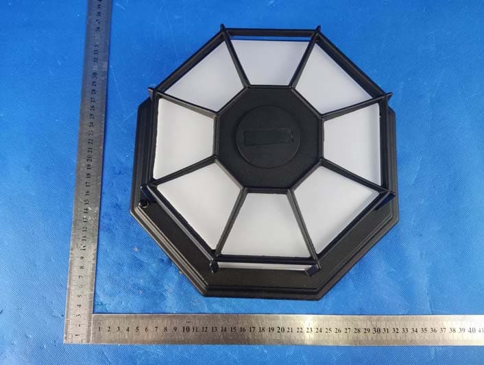
Click to zoom
Application Details
- Equipment Class
- DXX - Part 15 Low Power Communication Device Transmitter
- Date of Grant
- Oct 07, 2022
- Application Purpose
- Original Equipment
- Date of Application
- Oct 07, 2022
- Equipment Note
- Microwave sensor ceiling lamp
- Frequency Range
- 5735.25000000 - 5870.25000000
- Country
- China
Documents & Files
Document Text
Text extracted from the exhibit documents filed with the FCC. Open a document above to read the original.
Users Manual
Microware induction Ceiling Light Model CK-W06A-001 SPECIFICATIONS Range ................................................................Up to 24 ft. (8 m) Sensing Radius....................................................Up to 3m Electrical load - integrated LED .......................13Watts Lumens ..............................................................700lm Power Requirements ..........................................100-240VAC SAFETY INFORMATION Please read and understand this entire manual before at- tempting to assemble, operate, or install the product. is light xture require 100-240VAC.All wiring must be in accordance with the National Electrical Code (Canadian Electrical Code in Canada). Some local electrical codes WARNING • CAUTION • Do not cut any wires that have factory installed wire connectors or remove the wire connectors. PREPARATION Before beginning installation of product, make sure all parts are present. Compare parts with hardware contents list. If any part is missing or damaged, do not attempt to assemble, install, or operate the product. Tools Required for Assembly (not included): Phillips and meter, electrical tape, silicone sealant, safety glasses, work gloves, and ladder • Do not connect to dimmers or timers. • above the ground. Estimated Installation Time: 30 minutes HARDWARE CONTENTS Note: Illustrations may vary from actual unit. 2x – Wire Connectors 2x – Decorative Nut (Pre-installed) 2x – Mounting Screw DISASSEMBLE LIGHT FIXTURE 1. 2. Remove cover from base. LIGHT FIXTURE INSTALLATION or fuse. Place tape over circuit breaker switch and 1. Tighten mounting screws fnger tight 2. Attach mounting bracket to junction box using the two mounting bracket screws (supplied). Tighten securely. Junction Box Ground Screw Bracket Mounting Screws Mounting Bracket Mounting Screw 2 WIRING THE LIGHT FIXTURE Note: All wiring must be run in accordance with the Na- Black tional Electrical Code through conduit or another accept- able means. Green question as to the suitability of the system.or Bare Coppe r Twist the wires together and secure with wire connectors. 1. Route the junction box ground wire through the large White hole next to the ground screw (GND). Attach the ground wire under the ground screw. 2. Using the wire connectors: • Connect all white wires together. • Connect all black wires together. White to white Black to black Light Fixture 3 MOUNTING THE LIGHT FIXTURE 1. Make sure wire connectors and wires are inside the junction box. 2. Slide the xture base onto the mounting screw 3. Tighten the mounting screws securely against the light Junction Box Mounting Screw 4. use the two decorative nut to install the light xture cover. FCC Statement This device complies with part 15 of the FCC Rules. Operation is subject to the following two conditions: (1) This device may not cause harmful interference, and (2) this device must accept any interference received, including interference that may cause undesired operation. This equipment has been tested and found to comply with the limits for a Class B digital device, pursuant to Part 15 of the FCC Rules. These limits are designed to provide reasonable protection against harmful interference in a residential installation. This equipment generates uses and can radiate radio frequency energy and, if not installed and used in accordance with the instructions, may cause harmful interference to radio communications. However, there is no guarantee that interference will not occur in a particular installation. If this equipment does cause harmful interference to radio or television reception, which can be determined by turning the equipment off and on, the user is encouraged to try to correct the interference by one or more of the following measures: -- Reorient or relocate the receiving antenna. -- Increase the separation between the equipment and receiver. -- Connect the equipment into an outlet on a circuit different from that to which the receiver is connected. -- Consult the dealer or an experienced radio/TV technician for help. Changes or modifications not expressly approved by the party responsible for compliance could void the user's authority to operate the equipment. This equipment complies with FCC radiation exposure limits set forth for an uncontrolled environment. This equipment should be installed and operated with minimum distance 20cm etween the radiator & your body. 4
External Photos
Page 1 of 3 FCC ID: 2A77M-CK-W06A-001 Dongguan Yaxu (AiT) Technology Limited No.22, Jinqianling 3rd Street, Jitigang, Huangjiang, Dongguan, Guangdong, China. External Photos Photo 1 Photo 2 Page 2 of 3 FCC ID: 2A77M-CK-W06A-001 Dongguan Yaxu (AiT) Technology Limited No.22, Jinqianling 3rd Street, Jitigang, Huangjiang, Dongguan, Guangdong, China. Photo 3 Photo 4 Page 3 of 3 FCC ID: 2A77M-CK-W06A-001 Dongguan Yaxu (AiT) Technology Limited No.22, Jinqianling 3rd Street, Jitigang, Huangjiang, Dongguan, Guangdong, China. Photo 5 Photo 6 ------End------
ID Label/Location Info
FCC ID Label
Internal Photos
Page 1 of 5 FCC ID: 2A77M-CK-W06A-001 Dongguan Yaxu (AiT) Technology Limited No.22, Jinqianling 3rd Street, Jitigang, Huangjiang, Dongguan, Guangdong, China. Internal Photos Photo 1 Photo 2 Page 2 of 5 FCC ID: 2A77M-CK-W06A-001 Dongguan Yaxu (AiT) Technology Limited No.22, Jinqianling 3rd Street, Jitigang, Huangjiang, Dongguan, Guangdong, China. Photo 3 Photo 4 Page 3 of 5 FCC ID: 2A77M-CK-W06A-001 Dongguan Yaxu (AiT) Technology Limited No.22, Jinqianling 3rd Street, Jitigang, Huangjiang, Dongguan, Guangdong, China. Photo 5 Photo 6 Page 4 of 5 FCC ID: 2A77M-CK-W06A-001 Dongguan Yaxu (AiT) Technology Limited No.22, Jinqianling 3rd Street, Jitigang, Huangjiang, Dongguan, Guangdong, China. Photo 7 Photo 8 Antenna Page 5 of 5 FCC ID: 2A77M-CK-W06A-001 Dongguan Yaxu (AiT) Technology Limited No.22, Jinqianling 3rd Street, Jitigang, Huangjiang, Dongguan, Guangdong, China. Photo 9 Photo 10 ------End------
Test Report
Page 1 of 33 Report No.: AIT22081810W1 Dongguan Yaxu (AiT) Technology Limited No.22, Jinqianling 3rd Street, Jitigang, Huangjiang, Dongguan, Guangdong, China. TEST REPORT Client Information: Applicant: DONGGUAN LUXMANN TECHNOLOGY CO., LTD Applicant add.: FLAT 101, Block 1,12 KONG YANG INDUSTRY STREET, ZHANG YANG, ZHANG MUTOU TOWN, DONG GUAN CITY, GUANGDONG PROVINCE ,CHINA 523636 Manufacturer: Dongguan Checkson Enterprise Co Ltd Manufacturer add.: 12 KONG YANG INDUSTRY STREET, ZHANG YANG, ZHANG MUTOU TOWN, DONG GUAN CITY, GUANGDONG PROVINCE ,CHINA 523636 Product Information: Product Name: Microwave sensor ceiling lamp Model No.: CK-W06A-001 Brand Name: Luxmann FCC ID: 2A77M-CK-W06A-001 Applicable standards: FCC CFR Title 47 Part 15 Subpart C Section 15.249 Prepared By: Dongguan Yaxu (AiT) Technology Limited No.22, Jinqianling 3rd Street, Jitigang, Huangjiang,Dongguan, Guangdong, China Tel.: +86-769-8202 0499 Fax.: +86-769-8202 0495 Date of Receipt: Aug. 18, 2022 Date of Test: Sep. 06~ Sep. 22, 2022 Date of Issue: Sep. 22, 2022 Test Result: Pass This device described above has been tested by Dongguan Yaxu (AiT) Technology Limited and the test results show that the equipment under test (EUT) is in compliance with the FCC requirements. And it is applicable only to the tested sample identified in the report. Note: This report shall not be reproduced except in full, without the written approval of Dongguan Yaxu (AiT) Technology Limited, this document may be altered or revised by Dongguan Yaxu (AiT) Technology Limited, personal only, and shall be noted in the revision of the document. This test report must not be used by the client to claim product endorsement. Reviewed by: Approved by: Simba Huang Seal.chen Page 2 of 33 Report No.: AIT22081810W1 Dongguan Yaxu (AiT) Technology Limited No.22, Jinqianling 3rd Street, Jitigang, Huangjiang, Dongguan, Guangdong, China. 1 Contents Page COVER PAGE 1 CONTENTS ..................................................................................................................................................... 2 2 TEST SUMMARY ............................................................................................................................................ 4 2.1 Statement of the Measurement Uncertainty .............................................................................. 4 2.2 Measurement Uncertainty ......................................................................................................... 4 3 TEST FACILITY ............................................................................................................................................... 5 3.1 Deviation from standard ............................................................................................................ 5 3.2 Abnormalities from standard conditions .................................................................................... 5 3.3 Test Location ............................................................................................................................. 5 4 GENERAL INFORMATION ............................................................................................................................. 6 4.1 Test frequencies ........................................................................................................................ 7 4.2 EUT Peripheral List ................................................................................................................... 8 4.3 Test Peripheral List ................................................................................................................... 8 4.4 TEST METHODOLOGY............................................................................................................ 9 4.5 Description of Test Modes ....................................................................................................... 10 5 EQUIPMENT USED DURING TEST ............................................................................................................. 11 6 TEST RESULTS AND MEASUREMENT DATA ........................................................................................... 12 6.1 Antenna requirement .............................................................................................................. 12 6.2 20 dB Spectrum Bandwidth Measurement .............................................................................. 13 6.3 Radiated Emissions Measurement ......................................................................................... 16 6.4 Conducted Emissions ............................................................................................................. 29 7 TEST SETUP PHOTO ................................................................................................................................... 33 8 EUT CONSTRUCTIONAL DETAILS ............................................................................................................. 33 Page 3 of 33 Report No.: AIT22081810W1 Dongguan Yaxu (AiT) Technology Limited No.22, Jinqianling 3rd Street, Jitigang, Huangjiang, Dongguan, Guangdong, China. Revision History Revision Issue Date Revisions Revised By 000 Sep. 22, 2022 Initial Issue Seal Chen Page 4 of 33 Report No.: AIT22081810W1 Dongguan Yaxu (AiT) Technology Limited No.22, Jinqianling 3rd Street, Jitigang, Huangjiang, Dongguan, Guangdong, China. 2 Test Summary Test Item Section in CFR 47 Result Antenna requirement §15.203 Pass AC Power Line Conducted Emission §15.207 Pass Fundamental &Radiated Spurious Emission Measurement §15.249 (a)/ §15.209 Pass 20dB Channel Bandwidth 15.215(c) Pass Band Edge §15.249 (d)/ §15.205 Pass Note 1. Test according to ANSI C63.10:2013. 2. The measurement uncertainty is not included in the test result. 2.1 Statement of the Measurement Uncertainty The data and results referenced in this document are true and accurate. The reader is cautioned that there may be errors withi…
Text truncated - open the document above for the full version.
Test Report
1. Antenna Description Antenna plate PCB Antenna Market name/Model name Manufacture Dongguan Checkson Enterprise Co Ltd Antenna Max. Gain 1dBi Frequency Range 5700.0‐5900.0MHz Connect Type PCB Antenna VSWR 1.1 2. Picture of antenna 12mm 3. Antenna Radiation Pattern Radiation pattern‐‐5.700GHz Total Average Gain: ‐0.12dBi Phi 0 45 90 135 180 235 270 315 Gain ‐0.12 0.30 ‐0.22 ‐0.11 ‐0.07 ‐0.24 ‐0.32 ‐0.21 Radiation pattern‐‐5.800GHz Total Average Gain: 0.03dBi Phi 0 45 90 135 180 235 270 315 Gain 0.15 1 ‐0.36 0.13 0.08 ‐0.27 ‐0.32 ‐0.15 Radiation pattern‐‐5.900GHz Total Average Gain: ‐0.17dBi Phi 0 45 90 135 180 235 270 315 Gain ‐0.14 0.25 ‐0.10 ‐0.12 ‐0.09 ‐0.11 ‐0.30 ‐0.18
Test Setup Photos
Page 1 of 2 FCC ID: 2A77M-CK-W06A-001 Dongguan Yaxu (AiT) Technology Limited No.22, Jinqianling 3rd Street, Jitigang, Huangjiang, Dongguan, Guangdong, China. Test Setup Photo Radiated Emission Page 2 of 2 FCC ID: 2A77M-CK-W06A-001 Dongguan Yaxu (AiT) Technology Limited No.22, Jinqianling 3rd Street, Jitigang, Huangjiang, Dongguan, Guangdong, China. Conducted Emission ------End------
Contact Information
Applicant
Kenny Lau(CEO)
Test Firm
Dongguan Yaxu (AiT) Technology LimitedCoin Tang
[email protected]+86 0769-82020499-21
Technical Specifications
| # | Rule Parts | Frequency Range | Power Output |
|---|---|---|---|
| 1 | 15C | 5.74 GHz - 5.87 GHz | - |