2A782-BRTS33-L2Band selective signal booster for improving radio coverage within confined areas with poor coverage
Semco Maritime A/S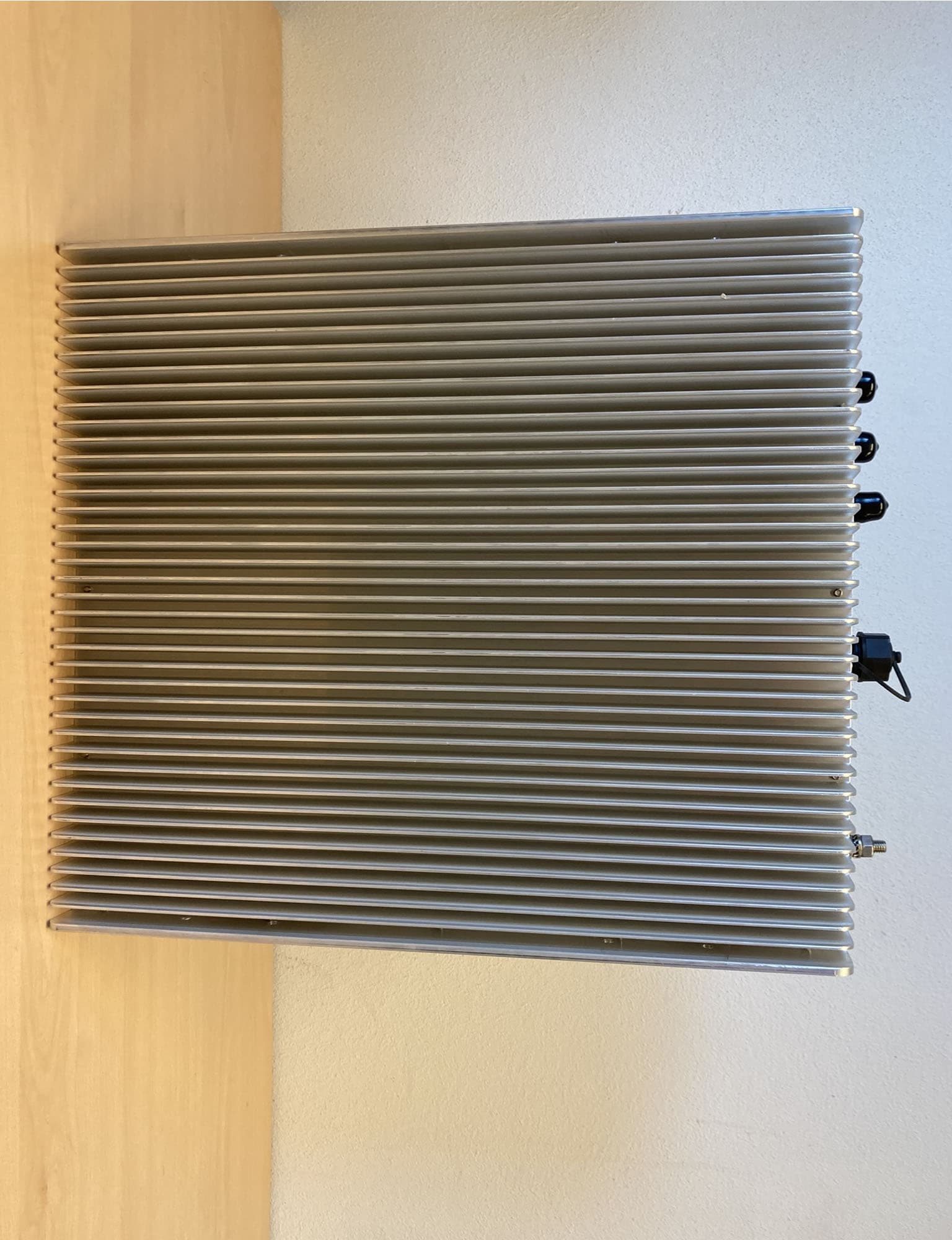
Click to zoom
Application Details
- Equipment Class
- B9B - Part 90 Class B Industrial Booster (non-SMR)
- Date of Grant
- Jan 04, 2023
- Application Purpose
- Original Equipment
- Date of Application
- Dec 10, 2022
- Equipment Note
- Band selective signal booster for improving radio coverage within confined areas with poor coverage
- Frequency Range
- 457.50000000 - 460.00000000
- Company
- Semco Maritime A/S
- Country
- Denmark
Documents & Files
Document Text
Text extracted from the exhibit documents filed with the FCC. Open a document above to read the original.
Users Manual
Revision no.: 1 Document no.: MA-SEMCO-0009 Page 1 of 17 BRTS33 Signal Booster User Manual User Manual BRTS33 – Signal Booster Revision no.: 1 Document no.: MA-SEMCO-0009 Page 2 of 17 About this manual This manual describes installation, commissioning, operation and maintenance of the BRTS33 Signal Booster, and the Operational and Maintenance Software. The first part of the manual describes the Signal Booster hardware and the second part describes the software. Hardware and software mentioned in this manual are subjected to continuous development and improvement. Consequently, there may be minor discrepancies between the information in the manual and the performance and design of the hardware and software. Specifications, dimensions and other statements mentioned in this manual are subject to change without notice. Rev. Date Changes to document 1 30-08-2022 Initial document release User Manual BRTS33 – Signal Booster Revision no.: 1 Document no.: MA-SEMCO-0009 Page 3 of 17 TABLE OF CONTENTS 1 Hardware ..................................................................................................................... 4 1.1 Safety ........................................................................................................................... 4 1.1.1 Dangerous Voltage Warning ......................................................................................... 4 1.1.2 R&TTE Compliance Statement ..................................................................................... 4 1.1.3 Station Ground ............................................................................................................. 4 1.1.4 Electrostatic Discharge ................................................................................................. 4 1.1.5 Disposal of Electric and Electronic Waste ..................................................................... 5 1.2 FCC Compliance .......................................................................................................... 5 1.2.1 Maximum Permissible Exposure for human safety ........................................................ 5 1.3 Product Description ...................................................................................................... 5 1.4 Installation .................................................................................................................... 6 1.4.1 Connector ports and indicator ....................................................................................... 7 2 Software ...................................................................................................................... 8 2.1 Product Finder .............................................................................................................. 8 2.2 First-time setup ............................................................................................................. 9 2.3 RF Configuration......................................................................................................... 10 2.3.1 Uplink/Downlink gain setting ....................................................................................... 10 2.3.2 Adaptive Gain ............................................................................................................. 10 2.3.3 Overdrive protection ................................................................................................... 11 2.3.4 Mute Function ............................................................................................................. 12 2.4 Alarm configuration ..................................................................................................... 12 2.4.1 Alarm Settings ............................................................................................................ 12 2.4.2 SNMP Settings ........................................................................................................... 13 2.4.3 RF Downlink Power alarm .......................................................................................... 15 2.5 Configuration Management ......................................................................................... 15 User Manual BRTS33 – Signal Booster Revision no.: 1 Document no.: MA-SEMCO-0009 Page 4 of 17 1 Hardware 1.1 Safety Caution! This manual lists a set of rules and warnings to be accomplished when installing, commissioning and operating a BRTS33 Signal Booster from Semco Maritime. Any omission may result in damage and/or injuries to the System and/or the System Operators or Users. If an instruction is not clear or you consider is missing, please make contact immediately to Semco Maritime. See www.semcomaritime.com for contact information. 1.1.1 Dangerous Voltage Warning Any personnel involved in installation, operation or service of this equipment must understand and obey the following: The power supply unit supplied from the main power contains dangerous voltage level, which can cause electric shock. Switch the main power off prior to any work in such equipment. Any local regulations are to be followed when servicing MOUs. Authorized service personnel only are allowed to service repeaters while the main is switched on. 1.1.2 R&TTE Compliance Statement This equipment complies with the appropriate essential requirements of 2014/53/EU (RED). 1.1.3 Station Ground BTS chassis, Signal Booster, feeders, donor antenna, service antenna/s and auxiliary equipment (splitters, tabs, .etc) are required to be bonded to protective grounding using the bonding stud or screw provided with each unit. 1.1.4 Electrostatic Discharge Static electricity means no risk of personal injury but it can severely damage essential parts of the Signal Booster, if not handled carefully. Parts on the printed circuit boards as well as other parts in the Signal Booster are sensitive to electrostatic discharge. Never touch printed circuit boards or uninsulated conductor surfaces unless absolu…
Text truncated - open the document above for the full version.
Attestation Statements
Page 1 of 1 Date 12-20-2022 Semco Maritime A/S Esbjerg Brygge 30 DK-6700 Denmark FCC ID: 2A782-BRTS33-L2____________ Product Name: _BRTS33-US-L2___________ The product is a class B signal booster and thereby the following warning label will be available for the product. Warning label messages and Class B disclosure will be also shown in online and point-of-sale marketing materials and on outside packaging of the device. Part 90 signal booster Warning. This is NOT a CONSUMER device. It is designed for installation by FCC LICENSEES and QUALIFIED INSTALLERS. You MUST have an FCC LICENSE or express consent of an FCC Licensee to operate this device. You MUST register Class B signal boosters (as defined in 47 CFR 90.219) online at www.fcc.gov/signal-boosters/registration. Unauthorized use may result in significant forfeiture penalties, including penalties in excess of $100,000 for each continuing violation The warning may look differently depending on the material where it is being presented. Dated this 20 Day of December 20 22 Martin S. Rossmann By: Signature Printed Title: Product Manager, Telecommunication On behalf of: Semco Maritime A/S Telephone: +45 7916 6490
Cover Letter(s)
Page 1 of 1 27-11-2022 Semco Maritime A/S Esbjerg Brygge 30 DK-6700 Denmark Nemko North America, Inc. 303 River Road Ottawa, Ontario, Canada K1V 1H2 AUTHORITY TO ACT AS AGENT - FCC On our behalf, I appoint Nemko Canada., to act as our agent in the preparation of this application for equipment certification. I certify that submitted documents properly describe the device or system for which equipment certification is sought. I also certify that each unit manufactured, imported or marketed, as defined in FCC regulations will have affixed to it a label identical to that submitted for approval with this application. In signing this letter, Applicant certifies that neither the applicant nor any party to the application is not subject to a denial of Federal benefits, that include FCC benefits, pursuant to Section 5301 of the Anti-Drug Abuse Act of 1988, 21 U.S.C. § 862 because of a conviction for possession or distribution of a controlled substance. See 47 CFR 1.2002(b) for the definition of a "party" for these purposes. For instances where our authorized agent signs the application for certification on our behalf, I acknowledge that all responsibility for complying with the terms and conditions for certification, as specified by Nemko North America Inc., still resides still resides with us. Sincerely, Printed name: Martin S. Rossmann
Cover Letter(s)
Page 1 of 2 Date 19-10-2022 Semco Maritime A/S Esbjerg Brygge 30 DK-6700 Denmark Equipment Autorisation Division Federal Communications Commission 7435 Oakland Mills Road Columbia, MD 21046 FCC ID: 2A782-BRTS33-L2____________ Product Name: _BRTS33-US-L2___________ Request for Confidentiality Pursuant to Sections 0.457(d) and 0.459 of the commissions rules, we hereby request that the following documents be held confidential: • Schematics • Block diagrams • Operation Description • Part list These materials contain registered technological patents and industrial property, then with strictly forbidden access to the public. The public disclosure of this information might be harmful to the company and provide unjustified benefits to competitors. Any potential leak out the Company of that information is prevented through confidentiality agreements signed by all internal personnel who, for design or production reasons, have been authorized to access them. The above listed internal photos are stored in the company internal servers, protected and keep strictly reserved, as stated in the company’s Quality Manual. Page 2 of 2 According to the clause II “LONG-TERM CONFIDENTIALITY”, item 3) of the FCC guide “726920 D01 Confidentiality Request Procedures v01r02”, we hereby declare that the following “special conditions” are applicable: a) user’s manual: this document is available to the end user, then excluded by this Long- Term Confidentiality request; b) additional description: b1 : not applicable, internal electronic is not serviceable; Dated this 19 Day of October 20 22 Martin S. Rossmann By: Signature Printed Title: Product Manager, Telecommunication On behalf of: Semco Maritime A/S Telephone: +45 7916 6490
ID Label/Location Info
Manufacturer: BHE Bonn Hungary Electronics Ltd. Addr.: Ipari Park Str.10. Budapest, Hungary Phone: (36-1) 233-2138 Telefax: (36-1) 233-2506 TETRA REPEATER Mains: 24VDC Power: 25W max. Type: BRTS33-US-L2 The repeater should be installed with connectors down! FCC ID: 2A782- BRTS33-L2 This device complies with part 15 of the FCC Rules. Operation is subject to the following two conditions: (1) This device may not cause harmful interference, and (2) this device must accept any interference received, including interference that may cause undesired operation. WARNING. This is NOT a CONSUMER device. It is designed for installation by FCC LICENSEES and QUALIFIED INSTALLERS. You MUST have an FCC LICENSE or express consent of an FCC Licensee to operate this device. You MUST register Class B signal boosters (as defined in 47 CFR 90.219) online at www.fcc.gov/signal-boosters/registration. Unauthorized use may result in significant forfeiture penalties, including penalties in excess of $100,000 for each continuing violation.” For contacting, visit us at www.semcomaritime.com 63,00 mm 190,00 mm
Parts List/Tune Up Info
Page 1 of 1 Semco Maritime A/S Esbjerg Brygge 30 DK-6700 Esbjerg Denmark FCC ID: 2A782-BRTS33-L2 Product Name: BRTS33-US-L2 Tune up Informations BRTS33-US-L2 is designed so that the switching range matches the alignment range. No tune up procedure is required by technicians or users after the equipment has left the factory to match its specifications on the working frequency. No manual trimmers or adjustments that can be manually done are implemented. Date__07-11-2022_________ Company name___Semco Maritime A/S____________ Name and Surname__Martin Rossmann_____ Position/Function_____Product Manager_____ Signature________________________
RF Exposure Info
Page 1 of 2 1. RF Exposure Requirements Systems operating under the provisions of this section shall be operated in a manner that ensures that the public is not exposed to radio frequency energy level in excess limit for maximum permissible exposure. In accordance with 47 CFR FCC Part 2 Subpart J, section 2.1091 this device has been defined as a mobile device whereby a distance of 20cm normally can be maintained between the user and the device. With the signal booster not being delivered with a standard antenna the assessment will be based on the maximum output power of the signal booster and the power density limits for the operating frequency. Thereby the maximum antenna gain can be derived and will be the determine factor for the RF safety compliance of the signal booster. 1.1. Limits The limits for the exposure calculations are used from FCC OET65 Appendix A, Table 1 Table 1 Limits for Occupational/Controlled Exposure Frequency Range (MHz) Electric Field Strength E (V/m) Magnetic Field Strength (H) (A/m) Power Density (S) (mW/cm 2 ) Averaging Time |E| 2 , |H| 2 or S (minutes) 0.3-3.0 614 1.63 (100)* 6 3.0-30 1842/f 4.89/f (900/f 2 ) 6 30-300 61.4 0.163 1.0 6 300-1500 -- -- f/300 6 1500-100,000 -- -- 5.0 6 Table 2 Limits for General Population/Uncontrolled Exposure Frequency Range (MHz) Electric Field Strength E (V/m) Magnetic Field Strength (H) (A/m) Power Density (S) (mW/cm 2 ) Averaging Time |E| 2 , |H| 2 or S (minutes) 0.3-1.34 614 1.63 (100)* 30 1.34-30 842/f 2.19/f (180/f 2 ) 30 30-300 27.5 0.073 0.2 30 300-1500 -- -- f/1500 30 1500-100,000 -- -- 1 30 f = frequency in MHz * Plane-wave equivalent power density Page 2 of 2 1.2. Equations The equation used to predict the maximum antenna gain allowed in the system is from FCC OET65 equation 3. 푆푆= 푃푃푃푃 4휋휋푅푅 2 Where: S = power density (in appropriate units, e.g. mW/cm 2 ) P = power input to antenna (in appropriate units e.g. mW) G = power gain of the antenna in the direction of interest to an isotropic antenna R = distance to the center of radiation of the antenna (appropriate units e.g. cm) The maximum antenna gain is the unit of interest and by re-arranging the equation the following is obtained: 푃푃= 4⋅휋휋⋅푅푅 2 ⋅푆푆 푃푃 With the gain in the above equation being expressed as a numeric gain it will be more common to show the gain as dBi, hence the below equation for converting the gain into dBi 푃푃 푑푑푑푑푑푑 = 10⋅퐿퐿퐿퐿퐿퐿 � 4⋅휋휋⋅푅푅 2 ⋅푆푆 푃푃 � 2. Assessment of BRTS33-US-Lx The signal booster range from Semco Maritime, BRTS33-US-Lx, covers the 450-460MHz range. Below are the details for the assessment of the system. • Frequency 455MHz • Output power: 17dBm • Power Density Limit: S = 455/1500≈0.3mW/cm 2 • Distance: 20cm 푃푃 푑푑푑푑푑푑 = 10⋅퐿퐿og� 4⋅휋휋⋅20 2 ⋅0.3 10 17/10 �= 14.78푑푑푑푑푑푑 From the above it is safe to use an antenna with an isotropic gain of 14dBi or less. The above does not include any cable or connector losses that will add to the safety of the system.
Test Report
C h o o s e S c a n d i n a v i a n t r u s t RADIO TEST REPORT – 465612TRFWL Type of assessment: Final product testing Applicant: Semco Maritime A/S Esbjerg Brygge 30 6700 Esbjerg Denmark Product: TETRA pico-repeater Model: BRTS33-US-L2 FCC ID: 2A782-BRTS33-L2 Specifications: FCC 47 CFR Part 90 Date of issue: July 13, 2022 P. Barbieri Tested by Signature D. Guarnone Reviewed by Signature Report reference ID: 465612TRFWL Page 2 of 85 Lab locations Company name Nemko Spa Address Via del Carroccio, 4 City Biassono Province MB Postal code 20853 Country Italy Telephone +39 039 220 12 01 Facsimile +39 039 220 12 21 Website www.nemko.com Site number 682159 (10 m semi anechoic chamber) Limits of responsibility Note that the results contained in this report relate only to the items tested and were obtained in the period between the date of initial receipt of samples and the date of issue of the report. This test report has been completed in accordance with the requirements of ISO/IEC 17025. All results contain in this report are within Nemko Spa ISO/IEC 17025 accreditation. Copyright notification Nemko Spa authorizes the applicant to reproduce this report provided it is reproduced in its entirety and for use by the company’s employees only. Any use which a third party makes of this report, or any reliance on or decisions to be made based on it, are the responsibility of such third parties. Nemko Spa accepts no responsibility for damages, if any, suffered by any third party as a result of decisions made or actions based on this report. Report reference ID: 465612TRFWL Page 3 of 85 Table of Contents Table of Contents ......................................................................................................................................................................................................... 3 Report summary ................................................................................................................................................................................. 4 1.1 Test specifications .................................................................................................................................................................................................... 4 1.2 Test methods ............................................................................................................................................................................................................ 4 1.3 Exclusions ................................................................................................................................................................................................................. 4 1.4 Statement of compliance .......................................................................................................................................................................................... 4 1.5 Test report revision history ....................................................................................................................................................................................... 4 Engineering considerations ................................................................................................................................................................. 5 2.1 Modifications incorporated in the EUT for compliance ............................................................................................................................................ 5 2.2 Technical judgment .................................................................................................................................................................................................. 5 2.3 Deviations from laboratory tests procedures ........................................................................................................................................................... 5 Test conditions ................................................................................................................................................................................... 6 3.1 Atmospheric conditions ............................................................................................................................................................................................ 6 3.2 Power supply range .................................................................................................................................................................................................. 6 Measurement uncertainty .................................................................................................................................................................. 7 4.1 Uncertainty of measurement ................................................................................................................................................................................... 7 Information provided by the applicant ................................................................................................................................................ 8 5.1 Disclaimer ................................................................................................................................................................................................................. 8 5.2 Applicant/Manufacture ............................................................................................................................................................................................ 8 5.3 EUT information ....................................................................................................................................................................................................... 8 5.4 Technical information ..........................................................................................................................…
Text truncated - open the document above for the full version.
Test Report
Section 8 Testing data Test name Spurious emissions conducted measurements Specification 935210 D05 Indus Booster Basic Meas v01r04 (4.7.3) Report reference ID: 465612TRFWL Page 66 of 85 Test data, continued Figure 8.6-2: Conducted spurious emissions, up link Section 8 Testing data Test name Spurious emissions radiated measurements Specification 935210 D05 Indus Booster Basic Meas v01r04 (4.9) Report reference ID: 465612TRFWL Page 67 of 85 8.7 Spurious emissions radiated measurements 8.7.1 References, definitions and limits FCC §90.210(b) Emission Mask B. For transmitters that are equipped with an audio low-pass filter, the power of any emission must be attenuated below the unmodulated carrier power (P) as follows: (1) On any frequency removed from the assigned frequency by more than 50 percent, but not more than 100 percent of the authorized bandwidth: At least 25 dB. (2) On any frequency removed from the assigned frequency by more than 100 percent, but not more than 250 percent of the authorized bandwidth: At least 35 dB. (3) On any frequency removed from the assigned frequency by more than 250 percent of the authorized bandwidth: At least 43 + 10 log (P) dB. FCC §90.219(e) (3) Spurious emissions from a signal booster must not exceed −13 dBm within any 100 kHz measurement bandwidth. 8.7.2 Test summary Verdict Pass Tested by P. Barbieri Test date July 9, 2022 8.7.3 Observations, settings and special notes The spectrum was searched from 30 MHz to the 10th harmonic. Testing was performed with RF ports terminated with 50 Ohm load. In the graphics below, no radiated spurious emission found and the limit is exceeded only by the carrier. Spectrum analyser settings: Resolution bandwidth: 100 kHz and 1 MHz Video bandwidth: VBW ≥ 3 × RBW Detector mode: Peak Trace mode: Max Hold Input signal frequency Down link 453.75 MHz Up link 458.75 MHz 8.7.4 Test equipment used Equipment Manufacturer Model no. Asset no. EMI Receiver Rohde & Schwarz ESW44 101620 RF Vector Signal Generator Rohde & Schwarz SMBV100A 263254 Antenna Trilog 25MHz - 8GHz Schwarzbeck Mess-Elektronik VULB9162 9162-025 Antenna 1 - 18 GHz Schwarzbeck Mess-Elektronik STLP9148 STLP 9148-152 Broadband Amplifier Schwarzbeck Mess-Elektronik BBV9718C 00121 Controller Maturo FCU3.0 10041 Tilt antenna mast Maturo TAM4.0-E 10042 Turntable Maturo TT4.0-5T 2.527 Semi-anechoic chamber Nemko S.p.a. 10m semi-anechoic chamber 530 Notes: NCR - no calibration required, VOU - verify on use Section 8 Testing data Test name Spurious emissions radiated measurements Specification 935210 D05 Indus Booster Basic Meas v01r04 (4.9) Report reference ID: 465612TRFWL Page 68 of 85 8.7.5 Test data Figure 8.7-1: Radiated spurious emissions below 1 GHz with antenna in horizontal polarization – down link Section 8 Testing data Test name Spurious emissions radiated measurements Specification 935210 D05 Indus Booster Basic Meas v01r04 (4.9) Report reference ID: 465612TRFWL Page 69 of 85 Test data, continued Figure 8.7-2: Radiated spurious emissions below 1 GHz with antenna in vertical polarization – down link Section 8 Testing data Test name Spurious emissions radiated measurements Specification 935210 D05 Indus Booster Basic Meas v01r04 (4.9) Report reference ID: 465612TRFWL Page 70 of 85 Test data, continued Figure 8.7-3: Radiated spurious emissions above 1 GHz with antenna in horizontal polarization – down link Section 8 Testing data Test name Spurious emissions radiated measurements Specification 935210 D05 Indus Booster Basic Meas v01r04 (4.9) Report reference ID: 465612TRFWL Page 71 of 85 Test data, continued Figure 8.7-4: Radiated spurious emissions above 1 GHz with antenna in vertical polarization – down link Section 8 Testing data Test name Spurious emissions radiated measurements Specification 935210 D05 Indus Booster Basic Meas v01r04 (4.9) Report reference ID: 465612TRFWL Page 72 of 85 Test data, continued Figure 8.7-5: Radiated spurious emissions below 1 GHz with antenna in horizontal polarization – up link Section 8 Testing data Test name Spurious emissions radiated measurements Specification 935210 D05 Indus Booster Basic Meas v01r04 (4.9) Report reference ID: 465612TRFWL Page 73 of 85 Test data, continued Figure 8.7-6: Radiated spurious emissions below 1 GHz with antenna in vertical polarization – up link Section 8 Testing data Test name Spurious emissions radiated measurements Specification 935210 D05 Indus Booster Basic Meas v01r04 (4.9) Report reference ID: 465612TRFWL Page 74 of 85 Test data, continued Figure 8.7-7: Radiated spurious emissions above 1 GHz with antenna in horizontal polarization – up link Section 8 Testing data Test name Spurious emissions radiated measurements Specification 935210 D05 Indus Booster Basic Meas v01r04 (4.9) Report reference ID: 465612TRFWL Page 75 of 85 Test data, continued Figure 8.7-8: Radiated spurious emissions above 1 GHz with antenna in vertical polarization – up link Section 8 Testing data Test name Frequency stability measurements Specification 935210 D05 Indus Booster Basic Meas v01r04 (4.8) Report reference ID: 465612TRFWL Page 76 of 85 8.8 Frequency stability measurements 8.8.1 References, definitions and limits FCC § 90.213(a) (a) Unless noted elsewhere, transmitters used in the services governed by this part must have a minimum frequency stability as specified in the following table. 7 In the 421-512 MHz band, fixed and base stations with a 12.5 kHz channel bandwidth must have a frequency stability of 1.5 ppm. Fixed and base stations with a 6.25 kHz channel bandwidth must have a frequency stability of 0.5 ppm. 8 In the 421-512 MHz band, mobile stations designed to operate with a 12.5 kHz channel bandwidth must have a frequency stability of 2.5 ppm. Mobile stations designed to operate with a 6.25 kHz channel bandwidth must have a frequency stability of 1.0 ppm. 11 Paging transmitters operating on paging-only frequencies must operate with frequency stability of 5 ppm in the 150-174 MHz band and 2.5 ppm in the…
Text truncated - open the document above for the full version.
Test Setup Photos
O N E W O R L D O U R A P P R O V A L Setup photos 465612TRFWL, 465612TRFEMC Date of issue: July 13, 2022 Applicant: Semco Maritime A/S Esbjerg Brygge 30 6700 Esbjerg Denmark Product name: TETRA pico-repeater Model: BRTS33-US-L2 FCC ID: 2A782-BRTS33-L2 Report reference ID: 465612TRFWL, 465612TRFEMC Page 2 of 9 Section 1. Setup photos 1.1 Radiated emissions set-up for frequencies below 1 GHz Report reference ID: 465612TRFWL, 465612TRFEMC Page 3 of 9 1.2 Radiated emissions set-up for frequencies above 1 GHz Report reference ID: 465612TRFWL, 465612TRFEMC Page 4 of 9 Section 2. Setup photos 2.1 Conducted emissions Report reference ID: 465612TRFWL, 465612TRFEMC Page 5 of 9 2.2 Receiver conducted emissions Report reference ID: 465612TRFWL, 465612TRFEMC Page 6 of 9 Section 3. Setup photos 3.1 Noise figure testing 3.2 Antenna port testing Report reference ID: 465612TRFWL, 465612TRFEMC Page 7 of 9 3.3 Antenna port testing in climatic chamber Report reference ID: 465612TRFWL, 465612TRFEMC Page 8 of 9 Section 4. Setup photos 4.1 EUT Report reference ID: 465612TRFWL, 465612TRFEMC Page 9 of 9
Contact Information
Applicant
Martin Rossmann
Test Firm
Nemko S.p.A.Roberto Giampaglia
Technical Specifications
| # | Rule Parts | Frequency Range | Power Output | Emission | Tolerance |
|---|---|---|---|---|---|
| 2 | 9 | 457.5 MHz - 460 MHz | 50.00 mW | D7W | Amp |
Other Applications from Semco Maritime A/S
2A782-BRTS33-L1
Jan 04, 2023Band selective signal booster for improving radio coverage within confined areas with poor coverage
Equipment Class
B9B - Part 90 Class B Industrial Booster (non-SMR)