2A7DW-T-DW7150HR2.4G Digital wireless rv backup camera system
TOPWELL INT'L ELECTRONICS CO.,LTD
Click to zoom
Application Details
- Equipment Class
- DTS - Digital Transmission System
- Date of Grant
- Aug 20, 2022
- Application Purpose
- Original Equipment
- Date of Application
- Aug 20, 2022
- Equipment Note
- 2.4G Digital wireless rv backup camera system
- Frequency Range
- 2412.00000000 - 2462.00000000
- Country
- China
Documents & Files
Document Text
Text extracted from the exhibit documents filed with the FCC. Open a document above to read the original.
Users Manual
1 2.4G Digital wireless rv backup camera system Thank you for purchasing our product, please read it thoroughly before operating and keep it for future reference. The Digital Wireless Rear Vision System will improve your ability to see behind your car, pickup truck, camper, travel trailer, fifth wheel trailer or motorhome. We have taken numerous measures to ensure that your product is delivered in top condition and will perform to your satisfaction. Before you install If you are not confident working with 12V/24V DC vehicle wiring, contact your vehicle manufacturer or your nearest retailer/installer to get a professional installation. Innovation: NO Interference This device is free from interferences coming from Bluetooth, smartphones,WI- FI routers, power lines and other various electrical equipment. Repair 1.Monitor and U Shape Mounting Bracket 2. Camera INTRODUCTION IMPORTANT SAFETY INSTRUCTIONS The camera system should not be opened. Any attempt at modification or repair by the user will void the warranty. PARTS 2 SD Card Slot (memory card not included, max support 128GB) 4. Monitor Power Cable These instructions do not apply to all vehicles. They are only meant as a general guide due to the number of different makes and models. For vehicle specific questions, contact your vehicle manufacturer. Camera Installation Caution Make sure there are no electrical cables, gas lines or important parts behind where the drill holes will be. Make sure to isolate the 12V or 24V power source by disconnecting the negative (-) terminal from the battery. Metal brackets for plain surfaces 3.Accessories Installation Detachable Sunshield Suction cup mount Remote ControlPower Cord Antenna Screws & Bolt User Manual clamps Power Adapter for Pre-Wired RV Furrion 3 Attention: The above accessories list may have little differences for different retail platforms, we may increase or update some accessories without notifying in advance, please subject to the actual received package. screw TA6x16 Washer ¢7 Camera location Allen Screw 4x8 Washer ¢5 Wiring Installation The system can be used as a rear observation system or as a backup camera system. ·To use as a rear observation system, the camera needs to be wired to a constant 12V/24V power source. Ex: If connected to running lights or marker lights, the lights must be ON for the system to operate. ·To use system as a backup camera system, the camera needs to be wired to a circuit that turns on when the reverse gear in engaged. Ex: Backup lights. 1.Chose routing path for the camera's power cable to the power source depending on the desired function. 4 Camera Positioning CAM 2.Before drilling the hole,make sure there are no components behind the surface you are drilling such as electrical cables,gas lines,or other important components that can be damaged. 3.After drilling the hole,insert the supplied grommet then route the camera cable into the opening. The grommet must be used to prevent the metal edge from cutting the cable. 4.Locate the power source required:Backup lights if used as a backup camera or running/marker lights is used as a rear observation system. 5.Once you have located the power source,route the camera cable to that location. Never route the cable on the outside of the vehicle. 6.Connect wires as diagram below. 7.Make sure the battery's negative terminal is disconnected. After determining the positive and negative wires, splice the wires using the quick connectors included. 8.Reconnect the negative terminal to the battery. Monitor Installation Make sure the monitor is mounted in a location that will not obstruct your vision while driving. 1.Suction Cup Mounting. a.Slide the suction cup mounting bracket's head into the monitor's back metal clip. b.Before mounting the monitor, clean the mounting surface well. c.Position the suction cup to your wind shield. d.Press the suction cup against the surface and press the lock down to fix it. 5 reversing light’s power GND 3.Feed the monitor’s power socket with the supplied cigarette lighter.The cable must not interfere with safe driving operations. 4.Insert cigarette lighter into the vehicle's power socket. 2.On dash mounting You can fix it on dash by using the original U shape bracket or purchase an extra surface mount bracket from our store. e.adjust the knob to set the screen at a good viewing angle and tighten knob on the bracket to lock into position. 6 To maximize the efficiency of the suction cup mount, it is recommended that the mounting be performed under the following conditions: ·Surface temperature should be between 21°C and 38°C. ·Mounting below 10°C should be avoided. ·Mounting should not occur in direct sunlight. Mounting should be protected from direct sunlight exposure for a period of 24 hours. Optional 5.Trigger singal wires conections Attention: The trigger signal wiring require professional techinical person to install, if you install one backup camera only, please ignore those wirings. a. After power is on,the red indicator is ON and the monitor will automatically enter into function. b. If there is no signal detected, the receiver LCD will turn off automatically.If there is a signal, the image is displayed and the LED is OFF. The buttons include Menu/Return,Rec/Confirm,SD (Memory),Power,-,+,CAM (channel) as shown below: OPERATION 1. Power Supply Power to the monitor is supplied with the vehicle's 12V/24V power socket. 2. Monitor Operation M Press to show OSD or return to the previous menu REC Start or stop recording/Confirm SD Enter into the recorded file route POWER Power on or off the monitor - Select forward in OSD operation + Select backward in OSD operation CAM Select the displayed camera channels or 2/4 split display mode 7 1. When the green wire is activated, the monitor automatically switches to CAM1. 2. When the blue wire is connected to the positive wire of the left turn light, the monitor automatically switches to CAM2(left side camera) when the left turn indicator is activat…
Text truncated - open the document above for the full version.
Attestation Statements
TOPWELLINT'LELECTRONICSCO.,LTD ModelDifference Productdescription:2.4GDigitalwirelessrvbackupcamerasystem Modelname:T-DW7150HR T-DW501HR,T-DW9020HR,T-M1012HR TradeName:N/A FCCID:2A7DW-T-DW7150HR AllthemodelarethesamecircuitandRFmodule,onlyformodelname. Regards Sincerely Client’ssignature: Client’sname/title:EricSun(N/A) Contactinformation/address:604,buildingB4,AnleIndustrialZone,172HangchengAvenue, Sanweicommunity,Hangchengstreet,Bao'anDistrict,Shenzhen
Cover Letter(s)
C5266091_X8_Ed.1 1/1 LetterofAuthorization <TOPWELLINT'LELECTRONICSCO.,LTD> Company:TOPWELLINT'LELECTRONICSCO.,LTD Address:604,buildingB4,AnleIndustrialZone,172HangchengAvenue, Sanweicommunity,Hangchengstreet,Bao'anDistrict,Shenzhen ProductName:2.4GDigitalwirelessrvbackupcamerasystem ModelNumber:T-DW7150HR T-DW501HR,T-DW9020HR,T-M1012HR FCCIdentifier:2A7DW-T-DW7150HR WeauthorizeLGAITechnologicalCenterS.A.,RondadelaFontdelCarme,s/n, 08193Bellaterra,Spain,toactonourbehalfonallmattersconcerningthe abovenamedequipment. AnyindividualwithinLGAITechnologicalCenterS.A.isauthorizedtoactonour behalfandtakeactionontheapplication. WedeclarethatauthorizeLGAITechnologicalCenterS.A.,RondadelaFontdel Carme,s/n,08193Bellaterra,Spain,isallowedtoforwardallinformation relatedtotheapprovalprojecttotheFederalCommunicationCommissionand todiscussanyissuesconcerningtheapprovalapplication.Anyandallacts carriedoutbyLGAITechnologicalCenterS.A.onourbehalfshallhavethe sameeffectasactsofourown. Name:EricSunDate:2022-08-12 Title:N/A Signatureofapplicant:
Cover Letter(s)
C5266091_X10_Ed.1 1/1 <TOPWELLINT'LELECTRONICSCO.,LTD> OfficeofEngineeringTechnology FederalCommunicationsCommission 7435OaklandMillsRoad Columbia,MD21046 Date:2022-08-12 Subject:RequestforConfidentiality FCCID:2A7DW-T-DW7150HR ToWhomItMayConcern, PursuanttotheprovisionsofSections0.457and0.459ofCommission'srules (47CFR0.457,0.459),wearerequestingtheCommissiontowithholdthefollowing attachment(s)asconfidentialdocumentfrompublicdisclosure. ExhibitsLong-Term Confidentiality Short-Term Confidentiality IDLabel/LocationNoNo AttestationStatementNoNo ExternalPhotosNo BlockDiagram Schematics TestReportNoNo TestSetupPhotosNo User’sManual InternalPhotos PartsList/TuneUp RFExposureInfo OperationalDescription CoverLetter(s)NoNo SDRSoftware/SecurityInfoNo Abovementioneddocumentcontainsdetailedsystemandequipmentdescriptionare consideredasproprietaryinformationinoperationoftheequipment.Thepublic disclosureofabovedocumentsmightbeharmfultoourcompanyandwouldgive competitoranunfairadvantageinthemarket. Itisourunderstandingthatallmeasurementtestreports,FCCIDlabelformatand correspondentduringcertificationreviewprocesscannotbegrantedasconfidential documentsandthoseinformationwillbeavailableforpublicreviewoncethegrantof equipmentauthorizationisissued. Sincerely, Signature: Name:EricSun Title:N/A
External Photos
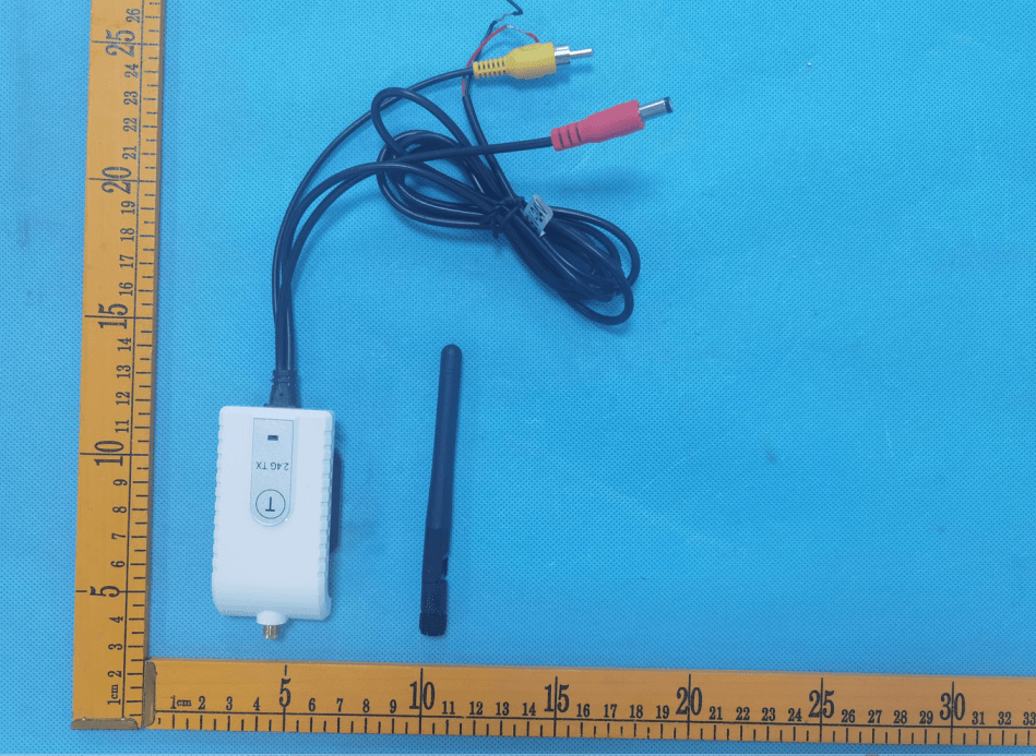
EUTPHOTO(ExternalPhotos) ANT
ID Label/Location Info
Labelandlabellocation 2.4GDigitalwirelessrvbackupcamerasystem FCCID:2A7DW-T-DW7150HR
Internal Photos
EUTPHOTO(InternalPhotos) ※※※※※ENDOFREPORT※※※※※
RF Exposure Info
FCCID:2A7DW-T-DW7150HR RFExposureEvaluation Limits Thecriterialistedinthefollowingtableshallbeusedtoevaluatetheenvironmentimpactofhumanexposure toradiofrequency(RF)radiationasspecifiedin1.1307(b) LimitsforMaximumPermissibleExposure(MPE) Frequencyrange (MHz) Electricfield strength (V/m) Magneticfieldstrength (A/m) Powerdensity (mW/cm 2 ) Averagingtime (minutes) (A)LimitsforOccupational/ControlledExposures 0.3–3.06141.63*(100)6 3.0–301842/f4.89/f*(900/f 2 )6 30–30061.40.1631.06 300–1500f/3006 1500–100,00056 (B)LimitsforGeneralPopulation/UncontrolledExposure 0.3–1.346141.63*(100)30 1.34–30824/f2.19/f*(180/f 2 )30 30–30027.50.0730.230 300–1500f/150030 1500–100,0001.030 f=frequencyinMHz Friistransmissionformula:Pd=(Pout*G)/(4*pi*r 2 ) Where Pd=powerdensityinmW/cm 2 ,Pout=outputpowertoantennainmW; G=gainofantennainlinearscale,Pi=3.1416; R=distancebetweenobservationpointandcenteroftheradiatorincm PdidthelimitofMPE,1mW/cm 2 .Ifweknowthemaximumgainoftheantennaandthetotalpowerinputto theantenna,throughthecalculation,wewillknowthedistancerwheretheMPElimitisreached. TestProcedure SoftwareprovidedbyclientenabledtheEUTtotransmitandreceivedataatlowest,middleandhighest channelindividually. TestResultofRFExposureEvaluation 2.4GWIFImode Mode Outputpower toantenna (dBm) Outputpowerto antenna(mW) PowerDensityat R=20cm (mW/cm 2 ) Limit (mW/cm 2 ) Result 802.11b12.59118.160.0036131.0PASS 802.11g11.73914.920.0029691.0PASS 802.11n2010.21110.500.0020881.0PASS 802.11n409.2518.420.0016741.0PASS Remark:antennagain=0dBi
Test Report
ProjectNo.:ZKT-2207134850E Page 1 of 56 FCCTESTREPORT FCCID:2A7DW-T-DW7150HR ReportNumber...................................:ZKT-2207134850E DateofTest.......................................................:Jul.13,2022toJul.21,2022 Dateofissue.........................................:Jul.21,2022 Totalnumberofpages .......................... 56 TestResult ............................................ : PASS TestingLaboratory............................: ShenzhenZKTTechnologyCo.,Ltd. Address...............................................: 1/F,No.101,BuildingB,No.6,TangweiCommunityIndustrial Avenue,FuhaiStreet,Bao'anDistrict,Shenzhen,China Applicant'sname.............................:TOPWELLINT'LELECTRONICSCO.,LTD Address...............................................: 604,buildingB4,AnleIndustrialZone,172HangchengAvenue, Sanweicommunity,Hangchengstreet,Bao'anDistrict,Shenzhen Manufacturer'sname ...................... :TOPWELLINT’LELECTRONICSCO.,LTD Address...............................................: 604,buildingB4,AnleIndustrialZone,172HangchengAvenue, Sanweicommunity,Hangchengstreet,Bao'anDistrict,Shenzhen Testspecification: Standard................................................: FCCCFRTitle47Part15SubpartCSection15.247 ANSIC63.10:2013 Testprocedure ..................................... : / Non-standardtestmethod ................ :N/A TestReportFormNo........................: TRF-EL-110_V0 TestReportForm(s)Originator.....: ZKTTesting MasterTRF........................................: Dated:2020-01-06 ThisdevicedescribedabovehasbeentestedbyZKT,andthetestresultsshowthattheequipmentunder test(EUT)isincompliancewiththeFCCrequirements.Anditisapplicableonlytothetestedsample identifiedinthereport. Thisreportshallnotbereproducedexceptinfull,withoutthewrittenapprovalofZKT,thisdocumentmay bealteredorrevisedbyZKT,personalonly,andshallbenotedintherevisionofthedocument. Productname ..................................... :2.4GDigitalwirelessrvbackupcamerasystem Trademark...........................................: N/A Model/Typereference ......................... :T-DW7150HR T-DW501HR,T-DW9020HR,T-M1012HR Ratings .................................................. :Input:DC12-24V ProjectNo.:ZKT-2207134850E Page 2 of 56 Testingprocedureandtestinglocation: TestingLaboratory ....................................... :ShenzhenZKTTechnologyCo.,Ltd. Address ............................................................ :1/F,No.101,BuildingB,No.6,TangweiCommunity IndustrialAvenue,FuhaiStreet,Bao'anDistrict, Shenzhen,China TomZou Testedby(name+signature).......................: JacksonFang Reviewer(name+signature) ....................... : LakeXie Approved(name+signature) ....................... : ProjectNo.:ZKT-2207134850E Page 3 of 56 TableofContents Page 1.VERSION5 2.SUMMARYOFTESTRESULTS6 2.1TESTFACILITY7 2.2MEASUREMENTUNCERTAINTY7 3.GENERALINFORMATION8 3.1GENERALDESCRIPTIONOFEUT8 3.2DESCRIPTIONOFTESTMODES9 3.3BLOCKDIGRAMSHOWINGTHECONFIGURATIONOFSYSTEMTESTED9 3.4DESCRIPTIONOFSUPPORTUNITS(CONDUCTEDMODE)10 3.5EQUIPMENTSLISTFORALLTESTITEMS11 4.EMCEMISSIONTEST13 4.1CONDUCTEDEMISSIONMEASUREMENT13 4.1.1POWERLINECONDUCTEDEMISSIONLIMITS13 4.1.2TESTPROCEDURE13 4.1.3DEVIATIONFROMTESTSTANDARD13 4.1.4TESTSETUP14 4.1.5EUTOPERATINGCONDITIONS14 4.1.6TESTRESULT15 4.2RADIATEDEMISSIONMEASUREMENT16 4.2.1RADIATEDEMISSIONLIMITS16 4.2.2TESTPROCEDURE16 4.2.3DEVIATIONFROMTESTSTANDARD17 4.2.4TESTSETUP17 4.2.5EUTOPERATINGCONDITIONS18 4.2.6TESTRESULTS18 5.RADIATEDBANDEMISSIONMEASUREMENT29 5.1TESTREQUIREMENT:29 5.2TESTPROCEDURE29 5.3DEVIATIONFROMTESTSTANDARD29 5.4TESTSETUP30 5.5EUTOPERATINGCONDITIONS30 5.6TESTRESULT31 6.POWERSPECTRALDENSITYTEST33 6.1APPLIEDPROCEDURES/LIMIT33 6.2TESTPROCEDURE33 6.3DEVIATIONFROMSTANDARD33 6.4TESTSETUP33 6.5EUTOPERATIONCONDITIONS33 ProjectNo.:ZKT-2207134850E Page 4 of 56 6.6TESTRESULT34 7.CHANNELBANDWIDTH&99%OCCUPYBANDWIDTH42 7.1APPLIEDPROCEDURES/LIMIT42 7.2TESTPROCEDURE42 7.3DEVIATIONFROMSTANDARD42 7.4TESTSETUP42 7.5EUTOPERATIONCONDITIONS42 7.6TESTRESULT43 8.PEAKOUTPUTPOWERTEST46 8.1APPLIEDPROCEDURES/LIMIT46 8.2TESTPROCEDURE46 8.3DEVIATIONFROMSTANDARD46 8.4TESTSETUP46 8.5EUTOPERATIONCONDITIONS46 8.6TESTRESULT47 9.CONDUCTEDBANDEDGEANDSPURIOUSEMISSION48 9.1APPLICABLESTANDARD48 9.2TESTPROCEDURE48 9.3DEVIATIONFROMSTANDARD48 9.4TESTSETUP48 9.5EUTOPERATIONCONDITIONS48 9.6TESTRESULTS48 10.ANTENNAREQUIREMENT55 11.TESTSETUPPHOTO56 12.EUTCONSTRUCTIONALDETAILS56 ProjectNo.:ZKT-2207134850E Page 5 of 56 1.VERSION ReportNo.VersionDescriptionApproved ZKT-2207134850ERev.01InitialissueofreportJul.21,2022 ProjectNo.:ZKT-2207134850E Page 6 of 56 2.SUMMARYOFTESTRESULTS Testproceduresaccordingtothetechnicalstandards: FCCPart15(15.247),SubpartC Standard Section TestItemResultRemark FCCpart15.203/15.247 (c) AntennarequirementPASS FCCpart15.207ACPowerLineConductedEmissionN/A FCCpart15.247(b)(3)ConductedPeakOutputPowerPASS FCCpart15.247(a)(2)ChannelBandwidth&99%OCBPASS FCCpart15.247(e)PowerSpectralDensityPASS FCCpart15.247(d)BandEdgePASS FCCpart15.205/15.209SpuriousEmissionPASS NOTE: (1)”N/A”denotestestisnotapplicableinthisTestReport ProjectNo.:ZKT-2207134850E Page 7 of 56 2.1TESTFACILITY ShenzhenZKTTechnologyCo.,Ltd. Add.:1/F,No.101,BuildingB,No.6,TangweiCommunityIndustrialAvenue,FuhaiStreet,Bao'an District,Shenzhen,China FCCTestFirmRegistrationNumber:692225 DesignationNumber:CN1299 ICRegisteredNo.:27033 CABidentifier:CN0110 2.2MEASUREMENTUNCERTAINTY Thereporteduncertaintyofmeasurementy±U , whereexpendeduncertaintyUisbasedonastandard uncertaintymultipliedbyacoveragefactorofk=2 , providingalevelofconfidenceofapproximately95 % 。 No.ItemUncertainty 1 3mcamberRadiatedspurious emission(9KHz-30MHz) U=4.5dB 2 3mcamberRadiatedspurious emission(30MHz-1GHz) U=4.8dB 3 3mchamberRadiatedspurious emission(1GHz-6GHz) U=4.9dB 4 3mchamberRadiatedspurious emission(6GHz-40GHz) U=5.0dB 5ConducteddisturbanceU=3.2dB 6RFBandEdgeU=1.68dB 7RFpowerconductedU=1.86dB 8RFconductedSpuriousEmissionU=2.2dB 9RFOccupiedBandwidthU=1.8dB 10RFPowerSpectralDensityU…
Text truncated - open the document above for the full version.
Test Setup Photos
EUTTESTPHOTO
Contact Information
Applicant
Eric Sun(manager)
Technical Contact
Non-Technical Contact
Shenzhen ZKT Technology Co., Ltd.Lake xie
[email protected]0086-400 000 9970
Test Firm
Shenzhen ZKT Technology Co., Ltd.Lake Xie
[email protected]0086-13620010775
Technical Specifications
| # | Rule Parts | Frequency Range | Power Output |
|---|---|---|---|
| 1 | 15C | 2.41 GHz - 2.46 GHz | 18.16 mW |
Other Applications from TOPWELL INT'L ELECTRONICS CO.,LTD
2A7DW-T-W4
Jun 14, 20222.4G Wireless video transmitte
Equipment Class
DXX - Part 15 Low Power Communication Device Transmitter