2A7NLPURBTQWCFurniture Power Distribution Units, Attachment Plugs and Receptacles
Lew Electric Fittings Company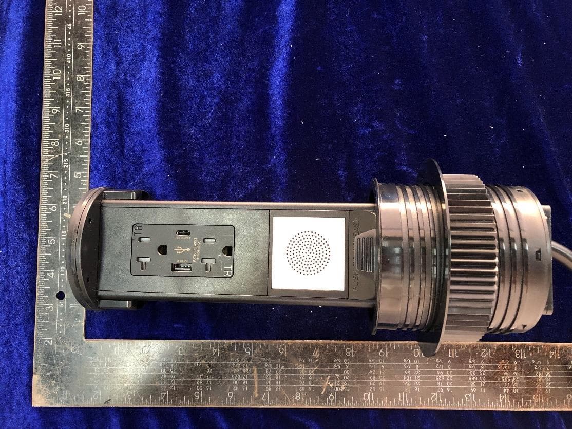
Click to zoom
Application Details
- Equipment Class
- DCD - Part 15 Low Power Transmitter Below 1705 kHz
- Date of Grant
- Nov 29, 2024
- Application Purpose
- Original Equipment
- Date of Application
- Nov 28, 2024
- Equipment Note
- Furniture Power Distribution Units, Attachment Plugs and Receptacles
- Frequency Range
- 0.11100000 - 0.20500000
- Country
- United States
Documents & Files
Document Text
Text extracted from the exhibit documents filed with the FCC. Open a document above to read the original.
Users Manual
(PUR) POP UP RECEPTACLE INSTALLATION INSTRUCTIONS FOR CATALOG NUMBERS: PURBTQWC Series IMPORTANT: Read all instructions before installing the PUR SERIES PRIOR TO INSTALLATION • Contact a local electrical inspector to make sure that this product meets or exceeds all local electrical codes (electric codes may vary by location). • Make sure there is adequate space to install (see below: CUT OUT AND MOUNTING STEPS) • Disconnect and turn off all power sources. CONDITIONS: • For indoor use only. • This product is designed for countertops, desktops, and similar surfaces (this product is not suitable for floor use). • All non GFI units must be wired to a GFCI circuit breaker if being installed in a kitchen, bathroom or any other area where the potential for water is present. • ELECTRIC CORD AND PLUG MAY NOT BE CUT OFF FOR HARDWIRING. DOING SO WILL NEGATE ANY WARRANTY OR RETURN OF MATERIAL. • Only licensed, insured, and bonded electrical contractors should install the PUR series. • These products have no field serviceable parts. If the product is damaged, it must be returned to the factory. Any attempt to alter this product in any way may cause electrocution. • Lew Electric accepts no responsibility if the above conditions are not followed. CUTOUT AND MOUNTING STEPS • -Select the desired location of the countertop or desktop at least 10” from stove top or other heating sources. • -The selected location must be at least 20mm (13/16”) away from the edge of the countertop or similar surface. • -The mounting surface must be between 9.5mm (3/8”) and 55mm (2 3/16”) thick and have the below clearances: UL listed electrical outlet box must be installed underneath the countertop by a licensed electrician. 1. Cut hole in surface of countertop 95.25 mm (3 ¾ ”). MAXIMUM HOLE SIZE NOT TO EXCEED 4 INCHES 2. Remove plastic threaded locking flange from PUR unit. 3. Feed power cord through hole in countertop first, followed by PUR unit, pushing down until black gasket resting on countertop. 4. Feed power cord through plastic locking flange and thread flange counterclockwise until locked in place against back of countertop. SEE BACKSIDE FOR REST OF INSTRUCTIONS 5. Plug power cord into electrical outlet box underneath countertop. 6. Remove plastic protective film from cover and discard. 7. To open pop up feature, press firmly on cover. Unit will deploy upward approximately 1” initially, then pull cover upward until unit locks into place. 8. To close device, push the red plastic locking tab and push down on cover until unit locks. NOTE FOR PUR-Qi MODELS: TYPE BUZZER Standby 2 Beeps Charging 1 Beep OTP (Over-Temperature Protection) OVP (Over Voltage Protection) OCP (Over Current Protection) Long Beep 5 minutes FOD (Foreign Object Detection) Long Beep 5 minutes NOTE CONNECTION STEPS FOR BLUETOOTH MODELS: 1. Long press the switch button for 3 seconds, when you hear the sound of “power on”, it means that the Bluetooth speaker has been activated. (Also, Long press the switch button for 3 seconds, when you hear the sound of “power off”, it means that the Bluetooth speaker has been turned off.) 2. The “Bluetooth speaker04” will be found in the Bluetooth options of the paired device. 3. Click "Bluetooth Speaker04" to complete pairing. NOTE: Countertop unit must be cut in as specified. In order for unit to deploy, the metal flange and black neoprene gasket must be on top of countertop to create counter pressure. Attempting to cut a larger hole to draw down the cover closer to the countertop will not allow the cover to deploy as there is not enough counter pressure to make the unit release. There will be a 3/16” gap when cover is closed, however, the watertight rating will still be valid as no liquid or solid can penetrate the gasket. A matching outer flange trim rings ships with every PUR, it can be installed to provide a more contoured look with the countertop. However, this look is personal preference, you may like the look with or without it. If you wish to install, place a small bead of silicone on the bottom of the ring, then place on counter around pop up and allow 24 hours to dry. For further instruction, please visit our website at www.lewelectric.com to see video of these types of units installed. Or, use your smart phone to read the QR code from the label on these devices. This device complies with part 15 of the FCC Rules. Operation is subject to the following two conditions: (1) This device may not cause harmful interference, and (2) this device must accept any interference received, including interference that may cause undesired operation. Caution: Changes or modifications to this unit not expressly approved by the party responsible for compliance could void the user's authority to operate the equipment. NOTE: This equipment has been tested and found to comply with the limits for a Class B digital device, pursuant to part 15 of the FCC Rules. These limits are designed to provide reasonable protection against harmful interference in a residential installation. This equipment generates, uses and can radiate radio frequency energy and, if not installed and used in accordance with the instructions, may cause harmful interference to radio communications. However, there is no guarantee that interference will not occur in a particular installation. If this equipment does cause harmful interference to radio or television reception, which can be determined by turning the equipment off and on, the user is encouraged to try to correct the interference by one or more of the following measures: —Reorient or relocate the receiving antenna. —Increase the separation between the equipment and receiver. —Connect the equipment into an outlet on a circuit different from that to which the receiver is connected. —Consult the dealer or an experienced radio/TV technician for help. To satisfy RF exposure requirements, a separation distance of 20 cm or more should be maintained between the antenna of this device and persons during devic…
Text truncated - open the document above for the full version.
Cover Letter(s)
Cover Letter for Wireless Charger Data:2024-09-20 Dear Sir/Madam, There’s a Furniture Power Distribution Units that would like to have your authorization as an Inductive wireless power transfer applications approval. The specific product as below Wireless Charger with its designed features and specified description, meets special requirements for KDB 680106 D01 section 5.2 requirements. Applicant: Lew Electric Fittings Company Product Description: The EUT is a Furniture Power Distribution Units, Attachment Plugs and Receptacles which supports Bluetooth and Wireless charging function. Model No: PUR/xx/xxxx/BTQWC-xxxx, PUR/xx/xxxx/BTQD-xxxx FCC ID: 2A7NLPURBTQWC Requirement Technical Result 1) Power transfer frequency is less than 1 MHz 111-205kHz Complied 2) The output power from each transmitting element coil is less than or equal to 15 watts 15W Complied 3) A client device providing the maximum permitted load is placed in physical contact with the transmitter Please refer to test report and RF exposure report. Complied 4) Mobile exposure conditions only Mobile Complied 5) The E-field and H-field strengths, at and beyond 20 cm surrounding the device surface, are demonstrated to be less than 50% of the applicable MPE limit. H-field strengths at 15 cm surrounding the device and 20cm above the top surface from all simultaneous transmitting coils is less than 50% of the MPE limit. Complied 6) For systems with more than one radiating structure, the conditions specified in (5) must be met when the system is fully loaded, and with all the radiating structures operating at maximum power at the same time. Please refer to RF exposure report. Complied
External Photos
Page 1 of 3 External Photos Page 2 of 3 Page 3 of 3
ID Label/Location Info
Label and location
Internal Photos
Page 1 of 10 Internal Photos Page 2 of 10 Page 3 of 10 Page 4 of 10 Page 5 of 10 Page 6 of 10 Page 7 of 10 Page 8 of 10 Page 9 of 10 Page 10 of 10
RF Exposure Info
Lew Electric Fittings Company MPE ASSESSMENT REPORT Report Type: FCC MPE assessment report Model: PUR/xx/xxxx/BTQWC-xxxx, PUR/xx/xxxx/BTQD-xxxx REPORT NUMBER: 240800131SHA-004 ISSUE DATE: November 1, 2024 DOCUMENT CONTROL NUMBER: TTRFFCCMPE-02_V1 © 2018 Intertek Intertek Testing Services (Shanghai FTZ) Co., Ltd. Building No.86, 1198 Qinzhou Road (North) Caohejing Development Zone Shanghai 200233, China Telephone: 86 21 6127 8200 www.intertek.com TEST REPORT This report is for the exclusive use of Intertek's Client and is provided pursuant to the agreement between Intertek and its Client. Intertek's responsibility and liability are limited to the terms and conditions of the agreement. Intertek assumes no liability to any party, other than to the Client in accordance with the agreement, for any loss, expense or damage occasioned by the use of this report. Only the Client is authorized to permit copying or distribution of this report and then only in its entirety. Any use of the Intertek name or one of its marks for the sale or advertisement of the tested material, product or service must first be approved in writing by Intertek. The observations and test results in this report are relevant only to the sample tested. This report by itself does not imply that the material, product, or service is or has ever been under an Intertek certification program. TTRFFCCMPE-02_V1© 2018 Intertek Page 2 of 10 Report no.: 240800131SHA-004 Applicant: Lew Electric Fittings Company 1626 Tobacco Rd, Augusta, GA 30906 Manufacturer: Zhejiang Sino Electro-Technical Co.,Ltd. A5 Building, Sulv Industrial Zone,Yueqing City, Zhejiang Province 325604 Manufacturer Site: Zhejiang Sino Electro-Technical Co.,Ltd. A5 Building, Sulv Industrial Zone,Yueqing City, Zhejiang Province 325604 Product Name: Furniture Power Distribution Units, Attachment Plugs and Receptacles Type/Model: PUR/xx/xxxx/BTQWC-xxxx, PUR/xx/xxxx/BTQD-xxxx FCC ID: 2A7NLPURBTQWC SUMMARY: The equipment complies with the requirements according to the following standard(s) or Specification: FCC PART 1 SECTION 1.1310 KDB447498 D01 General RF Exposure Guidance v06 KDB 680106 D01 Wireless Power Transfer v04 PREPARED BY: REVIEWED BY: Project Engineer Dylan Tang Reviewer Wakeyou Wang Report No.: 240800131SHA-004 TEST REPORT TTRFFCCMPE-01_V1© 2018 Intertek Page 3 of 10 Revision History Report No. Version Description Issued Date 240800131SHA-004 Rev. 01 Initial issue of report November 1, 2024 Report No.: 240800131SHA-004 TEST REPORT TTRFFCCMPE-01_V1© 2018 Intertek Page 4 of 10 Measurement result summary TEST ITEM FCC REFERANCE TEST RESULT NOTE RF Exposure 1.1310 Pass - Notes: 1: NA =Not Applicable 2: Determination of the test conclusion is based on IEC Guide 115 in consideration of measurement uncertainty. 3: Additions, Deviations and Exclusions from Standards: None. Report No.: 240800131SHA-004 TEST REPORT TTRFFCCMPE-01_V1© 2018 Intertek Page 5 of 10 1 GENERAL INFORMATION 1.1 Description of Equipment Under Test (EUT) Product name: Furniture Power Distribution Units, Attachment Plugs and Receptacles Type/Model: PUR/xx/xxxx/BTQWC-xxxx, PUR/xx/xxxx/BTQD-xxxx “xx”: denotes the current specification of receptacles, can be 15=15amp, 20=20amp “xxxx” denotes installed with different type receptacles, can be G=with a GFCI, DS=with a decora receptacle, AC=with an A/C receptacle, GAC=with a GFCI and an A/C receptacle, AC2P= with two A/C receptacles, no code=without receptacles “xxxx”: denotes different kind of tops, can be B=Brass top; SS=Stainless steel top; BK= Black painting top; WT= White painting top;DB= Dark bronze painting top; OW = Off white painting top; AWT= White painting top and white housing; NS= Nickel silver top; BS= Black stainless top; SN= Stain-nickel top; G=Graphite top; CB=Champagne Bronze top; RBK=Black PC top; RWT=Whtie pc top; RSS=Silver PC top; ROW= Off white PC top; RDB=Dark bronze pc top; RBR=Brass colored pc top; RAWT=White PC top base and white housing (XXXX can be 1 character, 2 characters, 3 characters or 4 characters) Description of EUT: The EUT is a Bluetooth Module which supports Bluetooth and Wireless charging function. The difference between the models is the AC Power line, and their circuitry is the same exactly. The model PUR/xx/xxxx/BTQWC-xxxx was chosen to test. Rating: 125V 15A for 15A receptacle 125V/120V 20A for 20A receptacle Category of EUT: Class B EUT type: Table top Floor standing Software Version: V1.0 Hardware Version: V1.0 Sample received date: January 15, 2024 Date of test: January 15, 2024 ~ March 5, 2024 1.2 Technical Specification Frequency Range: 111kHz – 205kHz Modulation: FSK Antenna: Coil antenna Report No.: 240800131SHA-004 TEST REPORT TTRFFCCMPE-01_V1© 2018 Intertek Page 6 of 10 1.3 Description of Test Facility Name: Intertek Testing Services (Shanghai FTZ) Co., Ltd. Address: Building 86, No. 1198 Qinzhou Road(North), Shanghai 200233, P.R. China Telephone: 86 21 61278200 Telefax: 86 21 54262353 The test facility is recognized, certified, or accredited by these organizations: CNAS Accreditation Lab Registration No. CNAS L21189 FCC Accredited Lab Designation Number: CN0175 IC Registration Lab CAB identifier.: CN0014 VCCI Registration Lab Registration No.: R-14243, G-10845, C-14723, T-12252 A2LA Accreditation Lab Certificate Number: 3309.02 Report No.: 240800131SHA-004 TEST REPORT TTRFFCCMPE-01_V1© 2018 Intertek Page 7 of 10 2 TEST SPECIFICATIONS 2.1 Standards or specification FCC PART 1 SECTION 1.1310 KDB 680106 D01 Wireless Power Transfer v04 KDB447498 D01 General RF Exposure Guidance v06 2.2 Mode of operation during the test Within this test report, EUT was tested under all modes and tested under its rating voltage and frequency. Other voltage and frequency are specified if used. The worst data was listed in the report. 2.3 Test peripherals list Item No. Name Band and Model Description 1 Wireless load iphone x 100% power level 2 Wireless load iphone x 50% power level 3 Wireless load iphone x 0% power level 2.4 Reco…
Text truncated - open the document above for the full version.
Test Report
Declaration Letter Related FCC ID: 2A7NLPURBTQWC All measurements were performed radiated. Therefore, additional antenna gain documentation is not required. See Internal photos for details of the antenna. By: ____ ___ _______ ____ ___Dylan Tang_______ (Signature) (Print name) Title: _____Certification Engineer_ Company: Intertek Testing Services Shanghai
Test Report
Lew Electric Fittings Company RF TEST REPORT Report Type: FCC Part 15C RF report Model: PUR/xx/xxxx/BTQWC-xxxx, PUR/xx/xxxx/BTQD-xxxx REPORT NUMBER: 240800131SHA-002 ISSUE DATE: November 1, 2024 DOCUMENT CONTROL NUMBER: TTRFFCCPART15C_V1 © 2018 Intertek Intertek Testing Services (Shanghai FTZ) Co., Ltd. Building No.86, 1198 Qinzhou Road (North) Caohejing Development Zone Shanghai 200233, China Telephone: 86 21 6127 8200 www.intertek.com TEST REPORT This report is for the exclusive use of Intertek's Client and is provided pursuant to the agreement between Intertek and its Client. Intertek's responsibility and liability are limited to the terms and conditions of the agreement. Intertek assumes no liability to any party, other than to the Client in accordance with the agreement, for any loss, expense or damage occasioned by the use of this report. Only the Client is authorized to permit copying or distribution of this report and then only in its entirety. Any use of the Intertek name or one of its marks for the sale or advertisement of the tested material, product or service must first be approved in writing by Intertek. The observations and test results in this report are relevant only to the sample tested. This report by itself does not imply that the material, product, or service is or has ever been under an Intertek certification program. TTRFFCCPART15C_V1 © 2018 Intertek Page 2 of 20 Report no.: 240800131SHA-002 Applicant: Lew Electric Fittings Company 1626 Tobacco Rd, Augusta, GA 30906 Manufacturer: Zhejiang Sino Electro-Technical Co.,Ltd. A5 Building, Sulv Industrial Zone,Yueqing City, Zhejiang Province 325604 Manufacturer Site: Zhejiang Sino Electro-Technical Co.,Ltd. A5 Building, Sulv Industrial Zone,Yueqing City, Zhejiang Province 325604 Product Name: Furniture Power Distribution Units, Attachment Plugs and Receptacles Type/Model: PUR/xx/xxxx/BTQWC-xxxx, PUR/xx/xxxx/BTQD-xxxx FCC ID: 2A7NLPURBTQWC SUMMARY: The equipment complies with the requirements according to the following standard(s) or Specification: 47CFR Part 15 (2023): Radio Frequency Devices (Subpart C) ANSI C63.10 (2020): American National Standard of Procedures for Compliance Testing of Unlicensed Wireless Devices PREPARED BY: REVIEWED BY: Project Engineer Dylan Tang Reviewer Wakeyou Wang Report No.: 240800131SHA-002 TEST REPORT TTRFFCCPART15C_V1 © 2018 Intertek Page 3 of 20 Content REVISION HISTORY................................................................................................................................................ 4 MEASUREMENT RESULT SUMMARY ..................................................................................................................... 5 1 GENERAL INFORMATION ............................................................................................................................. 6 1.1 DESCRIPTION OF EQUIPMENT UNDER TEST (EUT) ................................................................................................ 6 1.2 TECHNICAL SPECIFICATION ................................................................................................................................ 6 1.3 DESCRIPTION OF TEST FACILITY ......................................................................................................................... 7 2 TEST SPECIFICATIONS ................................................................................................................................... 8 2.1 STANDARDS OR SPECIFICATION .......................................................................................................................... 8 2.2 MODE OF OPERATION DURING THE TEST .............................................................................................................. 8 2.3 TEST SOFTWARE LIST ....................................................................................................................................... 8 2.4 TEST PERIPHERALS LIST..................................................................................................................................... 8 2.5 TEST ENVIRONMENT CONDITION: ....................................................................................................................... 8 2.6 INSTRUMENT LIST ........................................................................................................................................... 9 2.7 MEASUREMENT UNCERTAINTY ......................................................................................................................... 10 3 RADIATED EMISSIONS ............................................................................................................................... 11 3.1 LIMIT ......................................................................................................................................................... 11 3.2 MEASUREMENT PROCEDURE .......................................................................................................................... 11 3.3 TEST CONFIGURATION ................................................................................................................................... 12 3.4 TEST RESULTS OF RADIATED EMISSIONS ............................................................................................................ 14 4 CONDUCTED EMISSIONS ........................................................................................................................... 17 4.1 LIMIT ......................................................................................................................................................... 17 4.2 TEST CONFIGURATION ................................................................................................................................... 17 4.3 MEASUREMENT PROCEDURE .......................................................................................................................... 18 4.4 TEST RESULTS OF CONDU…
Text truncated - open the document above for the full version.
Test Setup Photos
Page 1 of 5 Test Setup Page 2 of 5 1. Radiated Emission Below 30MHz Below 1GHz Page 3 of 5 2. Conducted Emission Page 4 of 5 RF Exposure Page 5 of 5
Contact Information
Applicant
James Steven Cozzi
Technical Contact
Intertek Testing Services (Shanghai FTZ) Co., Ltd.Dylan Tang
[email protected]86 21 61215125
Building No.86, 1198 Qinzhou Road (North) · Shanghai · China
Test Firm
Intertek Testing Services (Shanghai FTZ) Co., Ltd.Leah Xu
[email protected]86-21-61278200
Technical Specifications
| # | Rule Parts | Frequency Range | Power Output |
|---|---|---|---|
| 1 | 15C | 0.111 MHz - 0.205 MHz | - |