2A7OE-001VTROTH A9 WIFI Camera
Wuyi Zhifeng Arts & Crafts Co., Ltd.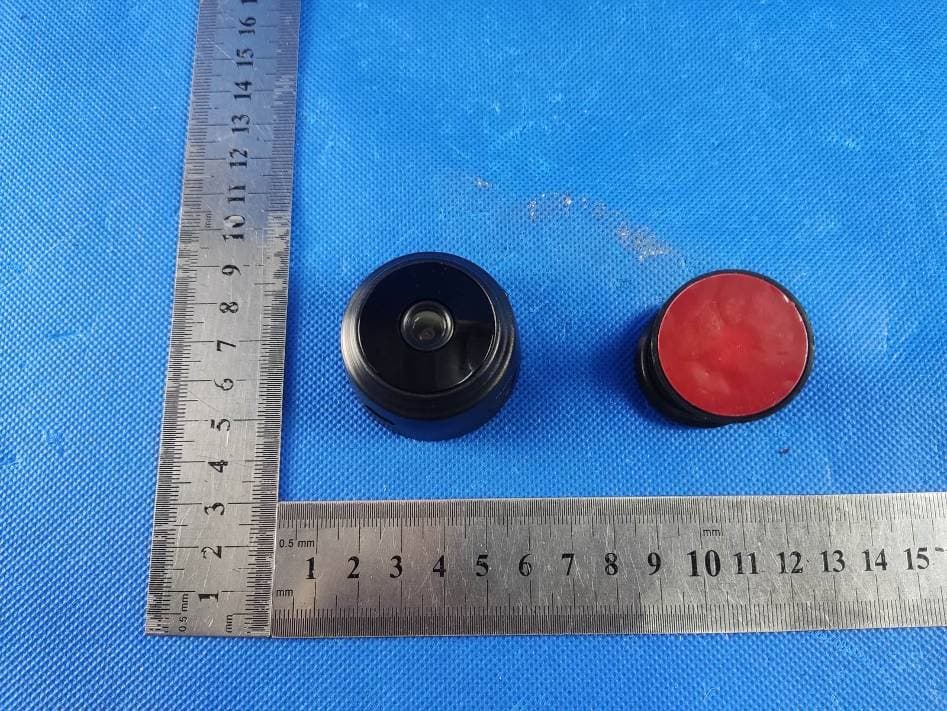
Click to zoom
Application Details
- Equipment Class
- DTS - Digital Transmission System
- Date of Grant
- Jul 17, 2022
- Application Purpose
- Original Equipment
- Date of Application
- Jul 17, 2022
- Equipment Note
- VTROTH A9 WIFI Camera
- Frequency Range
- 2412.00000000 - 2462.00000000
- Country
- China
Documents & Files
Document Text
Text extracted from the exhibit documents filed with the FCC. Open a document above to read the original.
Users Manual
HD smart life camera use guide Mobile App Installation Product button and indicator description 1、Download and install 365Cam, IOS is downloaded from Apple Store, Android system is searched in GooglePlay. To facilitate the installation, please scan the QR code below to download 365Cam. If your device cannot connect to GooglePlay, please scan the APK QR code below to download and install. Note: It is recommended to use the browser's own or third-party QR code scanning software to scan and download the App, WeChat sweep function does not support the direct download and installation of App files. ON/OFF: [ON key, press the button to turn on; press and hold to turn off after turning on] MODE: Press and hold for 5 seconds to restore the factory settings and disconnect the network connected to the monitor Charging indicator (blue):Long light when charging, off when full Work indicator (red):Blinking/long light is on state (Note: All permissions must be opened when downloading the app) 1. slow flash, ap hotspot mode, Network indicator (red): 2, long light, the device is successfully connected to wifi 3. Fast flashing, device connection failed, wifi password input error Note: When the camera working state is unknown, please reset the camera to restore factory settings (press and hold the camera reset button for more than 5 seconds), the camera reboot after opening the AP mode, wif indicator slow flash (3 seconds flash once). 2. Click "+" to add a device. Click "Device AP Network Configuration". 2. Click "Go to WiFi Configuration" to jump to the WIFI connection page and select ("DGO****×", "DBG****", "HTM****×*","TUT****") WIFI hotspot and connect. 3. After the connection is successful, return to the App, and the device is added successfully. (If the APP does not automatically add the device, you can click Search to add the searched device) u p and down aboutN i g ht visionC larityf u l l screen front page Configure external network VideoPhotoIndicator lightPhoto Video quality: H D R eal-time detection rate: 5 soundIndicator lightReplaysound 1. Click "+" to add a device. Click "Device AP Network Configuration". The second connection method 2,Select WiFi and enter the password, click "Next" and then click " Go to WiFi Configuration" 3. Jump to the WIFI connection page and select ("DGO****×", "DBG****", "HTM****×*", "TUT****") of the WIFI hotspot and connect. Return to the App after successful connection, the device is added successfully. (If the APP does not add the device automatically, you can click Searchto add the searched device) common problem. 1. When using this product for the first time, please fully cha 2. Remote monitoring is not smooth. Please choose the suitable clarity according to the network environment at that time. 3. The memory card does not save video, and it must be formatted the first time the memory card is used. 4. The default password of the camera is 6666. If you forget the user name or password, you can restore the camera to factory settings to get the default user name and password. 5. The camera is restored to its factory settings. Press the reset button of the camera for about 5 seconds until the camera restarts. 6. Why is the image blurry? Remove the protective film of the lens. If it is still not clear, please rotate the camera lens and focus. After focusing, a clear image can be obtained. 7.APP can't search to detect camera/can't configure network, please make sure the device is connected properly and check App Use permission is not restricted. If the application always shows failure, try checking the following items: A. It supports ordinary routers, and public routes that require login page authentication are temporarily not supported. B. When configuring, note that the network name, network password and UID are not incorrect. C. Chinese Wifi names and passwords and special symbols are not supported at the moment. D. Wifi signal that does not support 5G E. The device is not online and the red light is always on, indicating that the camera is connected to the network successfully, probably because the App permissions are not open. Please check whether to open. F. If WiFi is WEP encryption mode, please change it to WPA mode. This device complies with part 15 of the FCC Rules. Operation is subject to the following two conditions: Any Changes or modifications not expressly approved by the party responsible for compliance could void the user's authority to operate the equipment. Note: This equipment has been tested and found to comply with the limits for a Class B digital device, pursuant to part 15 of the FCC Rules. These limits are designed to provide reasonable protection against harmful interference in a residential installation. This equipment generates uses and can radiate radio frequency energy and, if not installed and used in accordance with the instructions, may cause harmful interference to radio communications. However, there is no guarantee that interference will not occur in a particular installation. If this equipment does cause harmful interference to radio or television reception, which can be determined by turning the equipment off and on, the user is encouraged to try to correct the interference by one or more of the following measures: This equipment complies with FCC radiation exposure limits set forth for an uncontrolled environment. This equipment should be installed and operated with minimum distance 20cm etween the radiator & your body. (1) This device may not cause harmful interference, and (2) this device must accept any interference received, including interference that may cause undesired operation. -Reorient or relocate the receiving antenna. -Increase the separation between the equipment and receiver. -Connect the equipment into an outlet on a circuit different from that to which the receiver is connected. -Consult the dealer or an experienced radio/TV technician for help.
External Photos
Page 1 of 4 FCC ID: 2A7OE-001 Dongguan Yaxu (AiT) Technology Limited No.22, Jinqianling 3rd Street, Jitigang, Huangjiang, Dongguan, Guangdong, China. External Photos Photo 1 Photo 2 Page 2 of 4 FCC ID: 2A7OE-001 Dongguan Yaxu (AiT) Technology Limited No.22, Jinqianling 3rd Street, Jitigang, Huangjiang, Dongguan, Guangdong, China. Photo 3 Photo 4 Page 3 of 4 FCC ID: 2A7OE-001 Dongguan Yaxu (AiT) Technology Limited No.22, Jinqianling 3rd Street, Jitigang, Huangjiang, Dongguan, Guangdong, China. Photo 5 Photo 6 Page 4 of 4 FCC ID: 2A7OE-001 Dongguan Yaxu (AiT) Technology Limited No.22, Jinqianling 3rd Street, Jitigang, Huangjiang, Dongguan, Guangdong, China. Photo 7 Photo 8 ------End------
ID Label/Location Info
FCC ID Label FCC ID:2A7OE-001
Internal Photos
Page 1 of 5 FCC ID: 2A7OE-001 Dongguan Yaxu (AiT) Technology Limited No.22, Jinqianling 3rd Street, Jitigang, Huangjiang, Dongguan, Guangdong, China. Internal Photos Photo 1 Photo 2 Page 2 of 5 FCC ID: 2A7OE-001 Dongguan Yaxu (AiT) Technology Limited No.22, Jinqianling 3rd Street, Jitigang, Huangjiang, Dongguan, Guangdong, China. Photo 3 Photo 4 Page 3 of 5 FCC ID: 2A7OE-001 Dongguan Yaxu (AiT) Technology Limited No.22, Jinqianling 3rd Street, Jitigang, Huangjiang, Dongguan, Guangdong, China. Photo 5 Photo 6 Page 4 of 5 FCC ID: 2A7OE-001 Dongguan Yaxu (AiT) Technology Limited No.22, Jinqianling 3rd Street, Jitigang, Huangjiang, Dongguan, Guangdong, China. Photo 7 Photo 8 Antenna Page 5 of 5 FCC ID: 2A7OE-001 Dongguan Yaxu (AiT) Technology Limited No.22, Jinqianling 3rd Street, Jitigang, Huangjiang, Dongguan, Guangdong, China. Photo 9 Photo 10 ------End------
RF Exposure Info
RF Exposure evaluation FCC ID: 2A7OE-001 Exposure category: General population/uncontrolled environment EUT Type: Production Unit Device Type: Mobile Device 1. Reference According to §1.1307(b)(1), systems operating under the provisions of this section shall be operated in a manner that ensures that the public is not exposed to radio frequency energy level in excess of the Commission’s guidelines. According to §1.1310 and §2.1091 RF exposure is calculated. KDB447498 D01: Mobile and Portable Devices RF Exposure Procedures and Equipment Authorization Policies 2. Limit Limits for Maximum Permissible Exposure (MPE)/Controlled Exposure Frequency Range(MHz) Electric Field Strength(V/m) Magnetic Field Strength(A/m) Power Density (mW/cm²) Averaging Time (minute) Limits for Occupational/Controlled Exposure 0.3 – 3.0 3.0 – 30 30 – 300 300 – 1500 1500 – 100,000 614 1842/f 61.4 / / 1.63 4.89/f 0.163 / / (100) * (900/f 2 )* 1.0 f/300 5 6 6 6 6 6 Limits for Maximum Permissible Exposure (MPE)/Uncontrolled Exposure Frequency Range(MHz) Electric Field Strength(V/m) Magnetic Field Strength(A/m) Power Density (mW/cm²) Averaging Time (minute) Limits for Occupational/Controlled Exposure 0.3 – 3.0 3.0 – 30 30 – 300 300 – 1500 1500 – 100,000 614 824/f 27.5 / / 1.63 2.19/f 0.073 / / (100) * (180/f 2 )* 0.2 f/1500 1.0 30 30 30 30 30 F=frequency in MHz *=Plane-wave equivalent power density 3. MPE Calculation Method Predication of MPE limit at a given distance Equation from page 18 of OET Bulletin 65, Edition 97-01 S=PG/4πR² Where: S=power density P=power input to antenna G=power gain of the antenna in the direction of interest relative to an isotropic radiator R=distance to the center of radiation of the antenna 4. Antenna Information Can only use antennas certificated as follows provided by manufacturer; Antenna No. Model No. of antenna: Type of antenna: Gain of the antenna (Max.) Frequency range: 2.4GWIFI / PCB Antenna 0dBi for 2412-2462MHz; 5. Manufacturing Tolerance 2.4GHz WLAN IEEE 802.11b (PEAK) Frequency (MHz) Antenna 1 2412 2437 2462 Target (dBm) 15 15 15 Tolerance ± (dB) 1.0 1.0 1.0 IEEE 802.11g (PEAK) Frequency (MHz) Antenna 1 2412 2437 2462 Target (dBm) 14 14 14 Tolerance ± (dB) 1.0 1.0 1.0 IEEE 802.11n HT20 (PEAK) Frequency (MHz) Antenna 1 2412 2437 2462 Target (dBm) 14 14 14 Tolerance ± (dB) 1.0 1.0 1.0 IEEE 802.11n HT40 (PEAK) Frequency (MHz) Antenna 1 2422 2437 2452 Target (dBm) 14 14 14 Tolerance ± (dB) 1.0 1.0 1.0 6. Standalone MPE Result As declared by the Applicant, the EUT is a wireless device used in a fix application, at least 20 cm from any body part of the user or nearby persons; from the maximum EUT RF output power, the minimum separation distance, r =20cm, as well as the gain of the used antenna is 2.54dBi, the RF power density can be obtained. Modulation Type Output power Antenna Gain (dBi) Antenna Gain (linear) MPE (mW/cm 2 ) MPE Limits (mW/cm 2 ) dBm mW 2.4GWIFI 16 39.811 0 1 0.00792 1.0000 Remark: 1. Output power (Peak) including turn-up tolerance; 2. MPE evaluate distance is 20cm from user manual provide by manufacturer. 7. Conclusion The measurement results comply with the FCC Limit per 47 CFR 2.1091 for the uncontrolled RF Exposure of mobile device. ----------------THE END OF REPORT---------------
Test Report
Page 1 of 42 Report No.: AIT22062210W1 Dongguan Yaxu (AiT) Technology Limited No.22, Jinqianling 3rd Street, Jitigang, Huangjiang, Dongguan, Guangdong, China. TEST REPORT Client Information: Applicant: Wuyi Zhifeng Arts & Crafts Co., Ltd. Applicant add.: No. 1, Xiapu Alley, Heshangliao Wangdalu Village, Baiyang Street Wuyi County, Zhejiang, China Manufacturer: Shenzhen Qiyou Creation Technology Co. Manufacturer add.: Shenzhen, Guangdong Province, China New Zhongtai Science and Technology Park 1-606, Longhua District, East Ring Road 1 Product Information: Product Name: VTROTH A9 WIFI Camera Model No.: 001 Brand Name: VTROTH FCC ID: 2A7OE-001 Applicable standards : FCC CFR Title 47 Part 15 Subpart C Section 15.247 Prepared By: Dongguan Yaxu (AiT) Technology Limited No.22, Jinqianling 3rd Street, Jitigang, Huangjiang,Dongguan, Guangdong, China Tel.: +86-769-8202 0499 Fax.: +86-769-8202 0495 Date of Receipt: June 22, 2022 Date of Test: June 22~June 29, 2022 Date of Issue: June 30, 2022 Test Result: Pass This device described above has been tested by Dongguan Yaxu (AiT) Technology Limited and the test results show that the equipment under test (EUT) is in compliance with the FCC requirements. And it is applicable only to the tested sample identified in the report. Note: This report shall not be reproduced except in full, without the written approval of Dongguan Yaxu (AiT) Technology Limited, this document may be altered or revised by Dongguan Yaxu (AiT) Technology Limited, personal only, and shall be noted in the revision of the document. This test report must not be used by the client to claim product endorsement. Reviewed by: Approved by: Simba Huang Seal.chen Page 2 of 42 Report No.: AIT22062210W1 Dongguan Yaxu (AiT) Technology Limited No.22, Jinqianling 3rd Street, Jitigang, Huangjiang, Dongguan, Guangdong, China. 1 Contents Page COVER PAGE 1CONTENTS .................................................................................................................................................................... 2 2TEST SUMMARY .......................................................................................................................................................... 5 2.1Statement of the Measurement Uncertainty .............................................................................. 5 2.2Measurement Uncertainty ......................................................................................................... 5 3TEST FACILITY ............................................................................................................................................................. 6 3.1Deviation from standard ............................................................................................................ 6 3.2Abnormalities from standard conditions .................................................................................... 6 3.3Test Location ............................................................................................................................. 6 4GENERAL INFORMATION ......................................................................................................................................... 7 4.1Test frequencies ........................................................................................................................ 8 4.2EUT Peripheral List ................................................................................................................... 8 4.3Test Peripheral List ................................................................................................................... 8 4.4TEST METHODOLOGY............................................................................................................ 9 4.5Description of Test Modes ....................................................................................................... 10 5EQUIPMENT USED DURING TEST ........................................................................................................................ 11 6TEST RESULTS AND MEASUREMENT DATA .................................................................................................... 12 6.1Antenna requirement .............................................................................................................. 12 6.1.1Standard requirement: .................................................................................................... 12 6.1.2EUT Antenna: ................................................................................................................. 12 6.2On Time and Duty Cycle ......................................................................................................... 13 6.2.1Standard requirement: .................................................................................................... 13 6.2.2Measuring Instruments and Setting: ............................................................................... 13 6.2.3Test Procedures .............................................................................................................. 13 6.2.4Test Setup Layout ........................................................................................................... 13 6.2.5EUT Operation during Test ............................................................................................. 13 6.2.6Test result ....................................................................................................................... 13 6.3Maximum Conducted Output Peak Power Measurement ....................................................... 14 6.3.1Standard requirement: .................................................................................................... 14 6.3.2Measuring Instruments: .................................................................................................. 14 6.3.3Test Procedures: ........…
Text truncated - open the document above for the full version.
Test Report
Dongguan Yaxu(AiT) Technology Limited Report No.: AIT22062210W1 FCC ID: 2A7OE-001 Page 1 of 56 Appendix C RF Test Data for 2.4GWIFI (Conducted Measurement) Product Name: VTROTH A9 WIFI Camera Trade Mark: VTROTH Test Model: 001 Environmental Conditions Temperature: 25.2 C Relative Humidity: 53.1% ATM Pressure: 100.0 kPa Test Engineer: Simba Huang Supervised by: Seal Chen Dongguan Yaxu(AiT) Technology Limited Report No.: AIT22062210W1 FCC ID: 2A7OE-001 Page 2 of 56 Contents Page COVER PAGE 1 Duty Cycle ........................................................................................................................................................................................... 3 1.1 Test Result ............................................................................................................................................................................... 3 1.2 Test Graphs ............................................................................................................................................................................. 4 2 Maximum Conducted Output Power ................................................................................................................................................. 10 2.1 Test Result ............................................................................................................................................................................. 10 3 -6dB Bandwidth ................................................................................................................................................................................. 11 3.1 Test Result ............................................................................................................................................................................. 11 3.2 Test Graphs ........................................................................................................................................................................... 12 4 Maximum Power Spectral Density Level ........................................................................................................................................... 18 4.1 Test Result ............................................................................................................................................................................. 18 4.2 Test Graphs ........................................................................................................................................................................... 19 5 Band Edge ......................................................................................................................................................................................... 25 5.1 Test Result ............................................................................................................................................................................. 25 5.2 Test Graphs ........................................................................................................................................................................... 26 6 Conducted RF Spurious Emission ..................................................................................................................................................... 34 6.1 Test Result ............................................................................................................................................................................. 34 6.2 Test Graphs ........................................................................................................................................................................... 35 7 Restrict Band ..................................................................................................................................................................................... 47 7.1 Test Result ............................................................................................................................................................................. 47 7.2 Test Graphs ........................................................................................................................................................................... 49 Dongguan Yaxu(AiT) Technology Limited Report No.: AIT22062210W1 FCC ID: 2A7OE-001 Page 3 of 56 1 Duty Cycle 1.1 Test Result Mode Frequency (MHz) Antenna Duty Cycle (%) 1/T (kHz) b 2412 Ant1 99.61 0.01 b 2437 Ant1 99.59 0.01 b 2462 Ant1 99.61 0.01 g 2412 Ant1 87.02 4.76 g 2437 Ant1 87.05 4.76 g 2462 Ant1 86.83 4.76 n20 2412 Ant1 87.58 4.35 n20 2437 Ant1 87.6 4.35 n20 2462 Ant1 87.58 4.35 n40 2422 Ant1 88.04 4.17 n40 2437 Ant1 88.07 4 n40 2452 Ant1 88.04 4.17 Dongguan Yaxu(AiT) Technology Limited Report No.: AIT22062210W1 FCC ID: 2A7OE-001 Page 4 of 56 1.2 Test Graphs Test Graphs b 2412MHz Ant1 b 2437MHz Ant1 Dongguan Yaxu(AiT) Technology Limited Report No.: AIT22062210W1 FCC ID: 2A7OE-001 Page 5 of 56 Test Graphs b 2462MHz Ant1 g 2412MHz Ant1 Dongguan Yaxu(AiT) Technology Limited Report No.: AIT22062210W1 FCC ID: 2A7OE-001 Page 6 of 56 Test Graphs g 2437MHz Ant1 g 2462MHz Ant1 Dongguan Yaxu(AiT) Technology Limited Report No.: AIT22062210W1 FCC ID: 2A7OE-001 Page 7 of 56 Test Graphs n20 2412MHz Ant1 n20 2437MHz Ant1 Dongguan Yaxu(AiT) Technology Limited Report No.: AIT22062210W1 FCC ID: 2A7OE-001 Page 8 of 56 Test Graphs n20 2462MHz Ant1 n40 2422MHz Ant1 Dongguan Yaxu(AiT) Technology Limited Report No.: AIT22062210W1 FCC ID: 2A7OE-001 Page 9 of 56 Test Graphs n40 2437MHz Ant1 n40 2452MHz Ant1 Dongguan Yaxu(AiT) Technology Limited Report No.: AIT22062210W1 FCC ID: 2A7OE-001 Page 10 of 56 2 Maximum Conducted Output Power 2.1 Test Result Mode Frequency (MHz) AntennaConducted Power (dBm)Limit (dBm) Verdict b 2412 Ant1 14.17 30 Pass b 2437 Ant1 14.26 30 Pass b 2462 Ant1 14.31 30 Pass g 2412 Ant1 14.07 30 Pass g 2437 Ant1 14.29 30 Pas…
Text truncated - open the document above for the full version.
Test Setup Photos
Page 1 of 2 FCC ID: 2A7OE-001 Dongguan Yaxu (AiT) Technology Limited No.22, Jinqianling 3rd Street, Jitigang, Huangjiang, Dongguan, Guangdong, China. Test Setup Photo Radiated Emission Page 2 of 2 FCC ID: 2A7OE-001 Dongguan Yaxu (AiT) Technology Limited No.22, Jinqianling 3rd Street, Jitigang, Huangjiang, Dongguan, Guangdong, China. Conducted Emission ------End------
Contact Information
Applicant
Feng Cheng(manager)
Test Firm
Dongguan Yaxu (AiT) Technology LimitedCoin Tang
[email protected]+86 0769-82020499-21
Technical Specifications
| # | Rule Parts | Frequency Range | Power Output |
|---|---|---|---|
| 1 | 15C | 2.41 GHz - 2.46 GHz | 27.00 mW |