2A7PFBGK713BIOGENIK UNA SMART WIFI 2PC RGBW BIOGLOW
Straight Forward Sales Inc.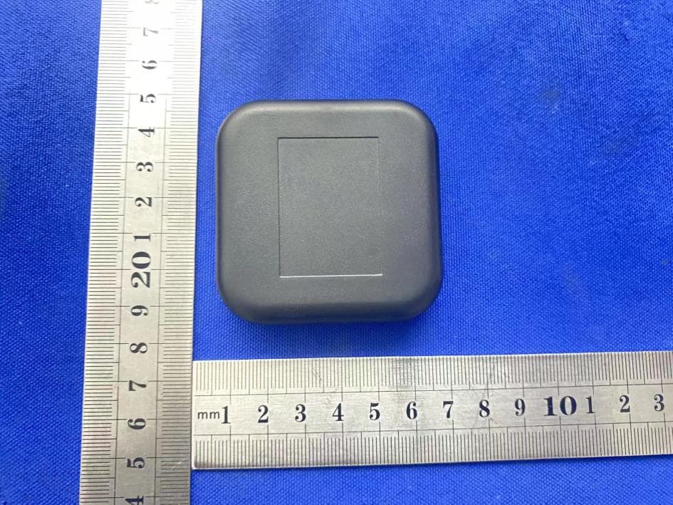
Click to zoom
Application Details
- Equipment Class
- DTS - Digital Transmission System
- Date of Grant
- Jul 03, 2022
- Application Purpose
- Original Equipment
- Date of Application
- Jul 03, 2022
- Equipment Note
- BIOGENIK UNA SMART WIFI 2PC RGBW BIOGLOW
- Frequency Range
- 2412.00000000 - 2462.00000000
- Company
- Straight Forward Sales Inc.
- Country
- Canada
Documents & Files
Document Text
Text extracted from the exhibit documents filed with the FCC. Open a document above to read the original.
Users Manual
2 barres lumineuses 1 adaptateur UL 1 manette de contrôle de lumière ambiante 1 câble de connexion entre l'adaptateur et la manette 3 papiers auto-adhésifs 3M 1 guide d’utilisation 1 carte de garantie 1.Téléchargez l’application et enregistrez votre compte. Ouvrez les paramètres Bluetooth de votre appareil mobile et connectez-vous à votre réseau Wi-Fi local. 2.Après avoir réussi à vous connecter, appuyez sur le bouton de marche/arrêt du contrôleur et maintenez-le enfoncé pendant au moins cinq secondes. Lorsque les barres lumineuses s’allument en rouge et clignotent rapidement, relâchez le bouton de marche/arrêt. Les barres lumineuses sont maintenant en mode découverte. 3.Ouvrez l’application sur votre appareil mobile et cliquez sur [Ajouter un appareil] ou sur le signe plus [+] dans le coin supérieur droit de l’écran. (Voir la Figure 1) Si vous avez besoin de déconnecter l’appareil, vous pouvez le faire directement depuis l’application. Cliquez sur le bouton situé au milieu de l’interface de contrôle des appareils pour accéder à la page de gestion d’appareils. Cliquez sur l’élément que vous désirez retirer. Fonctions de la manette Schéma d’installationFonctionProblème Contrôles tiers pris en charge 1. Si l’appareil ne peut pas être relié à l’application Smart Life, assurez-vous que l’appareil est sous tension, que le téléphone est connecté au Wi-Fi et que la fonction Bluetooth est activée. Lors de la première connexion, assurez-vous que votre téléphone intelligent est proche de l’appareil et du routeur. Assurez-vous que l’appareil est en mode découverte et que le voyant rouge clignote. Si ce n’est pas le cas, quittez l’application Smart Life, puis retournez dans l’application Smart Life pour vous connecter (assurez-vous que l’appareil est en mode découverte et que le voyant rouge clignote). 2. Réponse lente et perte de connexion. Assurez-vous que le réseau Wi-Fi est stable et que l’appareil est correctement alimenté. Quittez le programme Smart Life et entrez de nouveau dans le programme Smart Life pour vous reconnecter. 3. La sensibilité des appareils à la musique ne suffit pas. Assurez-vous que la manette est proche de la source de musique. Réglez la sensibilité de la musique à l’aide de l’application Smart Life. 4. Si l’adhésif fourni n’est pas assez collant, veuillez vous assurer qu’il soit sec et propre. Après avoir installé le support, appuyez fortement pendant quelques secondes pour vous assurer qu’il est bien fixé. Fonctionne avec Tuya Smart Fonctionne avec Smart Life Fonctionne avec Alexa Fonctionne avec Google Assistant Fonctionne avec SmartThings Fonctionne avec IFTTT Applications multiples Méthode 1 : 1.Tenez la barre lumineuse verticalement, en positionnant le support en dessous sur une surface plane 2.Fixez la barre lumineuse à la base, en utilisant les pinces pour l’aligner Méthode 2 : 1.Décollez le papier auto-adhésif 3M et collez-le sur la surface de base 2.Essuyez la surface adhésive, puis décollez l’autre face du papier adhésif et collez-la sur la surface. Bouton MARCHE/ARRÊT CCT MODÈLE Fonction Pression courte pour mettre en marche ou arrêter Pression longue de cinq secondes pour activer le mode découverte de l’appareil (le voyant lumineux rouge clignote rapidement) 4.Saisissez le mot de passe du réseau Wi-Fi actuellement connecté et cliquez sur [Suivant]. Les voyants deviennent blancs pour indiquer que la connexion est réussie. Lorsque cela se produit, cliquez sur [Suivant], puis sur [Terminer] dans le coin supérieur droit de l’écran pour terminer la configuration et entrer dans l’interface de contrôle principale de l’application. Si l’opération ci-dessus ne réussit pas, veuillez revenir à la première étape et recommencer le processus. BGK713 – BioGlow Smart RGB Light Bars USER MANUAL BGK713 – Barres lumineuses intelligentes RVB BioGlow GUIDE D’UTILISATION Package Contents Contenu de l’emballage Configuration du Wi-Fi Déconnecter l’appareil Télécharger l’application L’application peut être téléchargée sur la plupart des grands magasins d’applications dans le monde. Recherchez « Tuya Smart » ou « Smart Life » dans la boutique d’applications ou scannez le code QR ci-dessous. App Download Wi-Fi Setup Light Bar x 2 UL Adapter x 1 Ambient Light Controller x 1 Adapter to Controller Connection Cable x 1 3M Self-Adhesive Paper x 3 User Manual x 1 Warranty Card x 1 The app is available for download on most major app stores worldwide. Search for "Tuya Smart" or "Smart Life" in the app store or scan the QR code below. Unpair Device Controller Functions FunctionTroubleshooting Third Party Controls Supported 1. If the device cannot be linked to the Smart Life app, please make sure the device is powered on and the phone is connected to WIFI, and Bluetooth is turned on. When connecting for the first time, make sure your Smartphone is close to the device and the router. Make sure the device is in discovery mode and the red light is flashing. If not, please exit the Smart Life app and then go back into the Smart Life app to connect (make sure the device is in discovery mode and the red light is flashing). 2. Sluggish response and loss of connection. Make sure the WIFI network is stable, and the device is powered up properly. Exit the Smart Life program and re-enter the Smart Life program to reconnect. 3. Device music sensitivity is not enough. Make sure the controller is close to the music source. Adjust the music sensitivity using the Smart Life app. 4. If the adhesive provided is not sticky enough, please make sure it is dry and clean. After installing the bracket, press hard for a few seconds to make sure it sticks securely. Works with Tuya Smart Works with Smart Life Works with Alexa Works with Google Assistant Works with SmartThings Works with IFTTT Multiple Applications Method 1: 1.Hold light bar vertically, positioning stand below on flat surface 2.Affix light bar to base, using the clips to align the light bar Method 2: 1.Peel off the 3M self-adhesive paper and stick it to the…
Text truncated - open the document above for the full version.
Cover Letter(s)
Straight Forward Sales Inc. Agent Authorization Company: Straight Forward Sales Inc. Address: 89 Lorne Ave East, Stratford Ontario, Canada Product Name: BIOGENIK UNA SMART WIFI 2PC RGBW BIOGLOW LIGHT BARS Model Number(s): BGK713 Product Description: BIOGENIK UNA SMART WIFI 2PC RGBW BIOGLOW LIGHT BARS We authorize MiCOM Labs Inc., 575 Boulder Court, Pleasanton, California 94566, USA, to act on our behalf on all matters concerning the certification of above named equipment. We declare that MiCOM Labs Inc. is allowed to forward all information related to the approval and certification of equipment to the regulatory agencies as required and to discuss any issues concerning the approval application. Any and all acts carried out by MiCOM Labs on our behalf shall have the same effect as acts of our own. Signature: Date: 2022-06-29 Name: Matt Benjamin Title: CEO Company: Straight Forward Sales Inc.
Cover Letter(s)
Straight Forward Sales Inc. Office of Engineering Technology Federal Communications Commission 7435 Oakland Mills Road Columbia, MD 21046 USA Date: 2022/06/29 Subject; Request for Confidentiality FCC ID: 2A7PFBGK713 To Whom It May Concern, Pursuant to the provisions of the Commission’s rules Title 47 Sections §0.457 and §0.459, we are requesting the Commission to withhold the following attachment(s) as confidential documents from public disclosure indefinitely. These documents contain detailed system and equipment descriptions and are considered as proprietary information in operation of the equipment. The public disclosure of these documents might be harmful to our company and would give competitors an unfair advantage in the market. Schematic Diagram Block Diagram Operational Description In additional to above mentioned documents, in order to comply with the marketing regulations in Title 47 CFR §2.803 and the importation rules in Title 47 CFR §2.1204, while ensuring that business sensitive information remains confidential until the actual marketing of newly authorized devices, we request Short Term Confidentiality of the following attachment(s); User Manual For 45 days, pursuant to Public Notice DA 04-1705. OR For 180 days pursuantto KDB 726920 D01. It is our understanding that all measurement test reports, FCC ID label format and correspondence during the certification review process cannot be granted as confidential documents and this information will be available for public review once the grant of equipment authorization is issued. Sincerely, Signature: Name: Matt Benjamin Title: CEO
External Photos
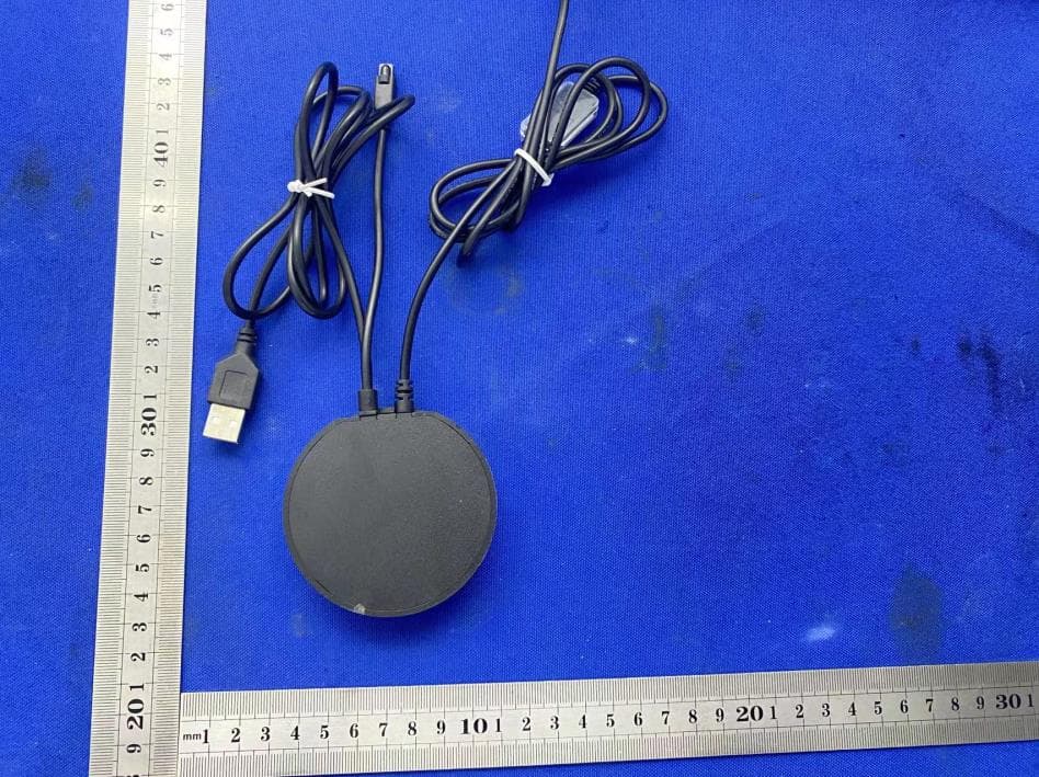
External Photos
ID Label/Location Info
Model: BGK713 FCC ID: 2A7PFBGK713 Label Location
Internal Photos
Internal Photos ANT
RF Exposure Info
FCC §15.247 (i), §2.1091 – RF Exposure FCC ID: 2A7PFBGK713 Applied procedures / limit According to FCC §15.247(i) and §1.1307(b)(1), systems operating under the provisions of this section shall be operated in a manner that ensures that the public is not exposed to radio frequency energy level in excess of the Commission’s guidelines. Limits for Occupational / Controlled Exposure Frequency Range (MHz) Electric Field Strength (E) (V/m) Magnetic Field Strength (H) (A/m) Power Density (S) (mW/ cm 2 ) Averaging Time |E| 2 ,|H| 2 or S (minutes) 0.3-3.0 614 1.63 (100)* 6 3.0-30 1842 / f 4.89 / f (900 / f)* 6 30-300 61.4 0.163 1.0 6 300-1500 F/300 6 1500-100,000 5 6 Note: ƒ is frequency in MHz * = Power density limit is applicable at frequencies greater than 100 MHz Limits for General Population / Uncontrolled Exposure Frequency Range (MHz) Electric Field Strength (E) (V/m) Magnetic Field Strength (H) (A/m) Power Density (S) (mW/ cm 2 ) Averaging Time |E| 2 ,|H| 2 or S (minutes) 0.3-1.34 614 1.63 (100)* 30 1.34-30 824/f 2.19/f (180/f)* 30 30-300 27.5 0.073 0.2 30 300-1500 F/1500 30 1500-100,000 1.0 30 Note: f = frequency in MHz * = Plane-wave equivalent power density MPE PREDICTION Predication of MPE limit at a given distance, Equation from OET Bulletin 65, Edition 97-01 Where: S = power density P = power input to antenna G = power gain of the antenna in the direction of interest relative to an isotropic radiator R = distance to the center of radiation of the antenna,R=20cm Test Result of RF Exposure Evaluation BT+WIFI supported simultaneous transmission: BLE+2.4GWIFI: ∑MPE Ratio =0.00030+0.00199 =0.00229≤1, So passed. Modes& Channel Freq. (MHz) Tune up Produce power Maximu m peak output power (dBm) Output power to antenna (mW) Antenna Gain (numeric) Power Density (S) (mW/ cm2) Limit (mW / cm2 ) Result 2.4G W IFI 802.11b&2 412 8±1 9 7.9433 1.2589 (1dBi) 0.00199 1 Pass BLE GFSK& 2440 1±1 2 1.1874 1.2589 (1dBi) 0.00030 1 Pass
Test Report
Shenzhen CTB Testing Technology Co., Ltd. Report No.: CTB220609022RF Report Tel: 4008-707-283 Web: http://www.ctb-lab.net Page 1 of 66 TEST REPORT Compiled by: Reviewed by: Approved by: Chen Zheng Arron Liu Bin Mei / Director Note: If there is any objection to the inspection results in this report, please submit a written report to the company within 15 days from the date of receiving the report. The test report is effective only with both signature and specialized stamp. This result(s) shown in this report refer only to the sample(s) tested. Without written approval of Shenzhen CTB Testing Technology Co., Ltd. this report can’t be reproduced except in full. The tested sample(s) and the sample information are provided by the client. “*” indicates the testing items were fulfilled by subcontracted lab. “#” indicates the items are not in CNAS accreditation scope. Product Name: BIOGENIK UNA SMART WIFI 2PC RGBW BIOGLOW LIGHT BARS FCC ID: 2A7PFBGK713 Trademark: Biogenik Model Number: BGK713 Prepared For: Straight Forward Sales Inc. Address: 89 Lorne Ave East, Stratford Ontario, Canada Manufacturer: Shenzhen Bryson Science Technology Co., Ltd Address: 4F, Building A, Yilai Industrial Zone, Shuitian Community, Shiyan Town, Shenzhen, China Prepared By: Shenzhen CTB Testing Technology Co., Ltd. Address: Floor 1&2, Building A, No. 26 of Xinhe Road, Xinqiao Community, Xinqiao Street, Baoan District, Shenzhen, Guangdong China Sample Received Date: May. 31, 2022 Sample tested Date: May. 31, 2022 to Jun. 09, 2022 Issue Date: Jun. 09, 2022 Report No.: CTB220609022RF Test Standards FCC Part15.247 ANSI C63.10:2013 Test Results PASS Remark: This is WIFI-2.4GHz band radio test report. Shenzhen CTB Testing Technology Co., Ltd. Report No.: CTB220609022RF Report Tel: 4008-707-283 Web: http://www.ctb-lab.net Page 2 of 66 TABLE OF CONTENT Test Report Declaration Page 1. VERSION............................................................ 4 2. TEST SUMMARY ..................................................... 5 3. MEASUREMENT UNCERTAINTY ....................................... 6 4. PRODUCT INFORMATION AND TEST SETUP ........................... 7 4.1 Product Information ..................................................... 7 4.2 Test Setup Configuration ................................................ 7 4.3 Support Equipment ..................................................... 7 4.4 Channel List ........................................................... 8 4.5 Test Mode ............................................................. 8 4.6 Test Environment ....................................................... 8 5. TEST FACILITY AND TEST INSTRUMENT USED ......................... 9 5.1 Test Facility ............................................................ 9 5.2 Test Instrument Used ................................................... 9 6. AC POWER LINE CONDUCTED EMISSION ............................. 12 6.1 Block Diagram Of Test Setup............................................ 12 6.2 Limit ................................................................. 12 6.3 Test procedure ........................................................ 12 6.4 Test Result ........................................................... 14 7. RADIATED SPURIOUS EMISSION ..................................... 16 7.1 Block Diagram Of Test Setup............................................ 16 7.2 Limit ................................................................. 16 7.3 Test procedure ........................................................ 17 7.4 Test Result ........................................................... 18 8. BAND EDGE AND RF COUNDUCTED SPURIOUS EMISSIONS ............ 40 8.1 Block Diagram Of Test Setup............................................ 40 8.2 Limit ................................................................. 40 8.3 Test procedure ........................................................ 40 8.4 Test Result ........................................................... 41 9. COUDUCTED OUTPUT POWER....................................... 49 9.1 Block Diagram Of Test Setup............................................ 49 9.2 Limit ................................................................. 49 9.3 Test procedure ........................................................ 49 9.4 Test Result ........................................................... 50 10. 6DB OCCUPIED BANDWIDTH ........................................ 51 10.1 Block Diagram Of Test Setup .......................................... 51 10.2 Limit ................................................................ 51 10.3 Test procedure ....................................................... 51 10.4 Test Result .......................................................... 52 11. POWER SPECTRAL DENSITY ........................................ 57 11.1 Block Diagram Of Test Setup .......................................... 57 11.2 Limit ................................................................ 57 Shenzhen CTB Testing Technology Co., Ltd. Report No.: CTB220609022RF Report Tel: 4008-707-283 Web: http://www.ctb-lab.net Page 3 of 66 11.3 Test procedure ....................................................... 57 11.4 Test Result .......................................................... 58 12. ANTENNA REQUIREMENT ........................................... 63 13. EUT PHOTOGRAPHS ................................................ 64 14. EUT TEST SETUP PHOTOGRAPHS ................................... 65 (Note: N/A means not applicable) Shenzhen CTB Testing Technology Co., Ltd. Report No.: CTB220609022RF Report Tel: 4008-707-283 Web: http://www.ctb-lab.net Page 4 of 66 1. VERSION Report No. Issue Date Description Approved CTB220609022RF Jun. 09, 2022 Original Valid Shenzhen CTB Testing Technology Co., Ltd. Report No.: CTB220609022RF Report Tel: 4008-707-283 Web: http://www.ctb-lab.net Page 5 of 66 2. TEST SUMMARY The Product has been tested according to the following specifi…
Text truncated - open the document above for the full version.
Test Report
Shenzhen CTB Testing Technology Co., Ltd. Report No.: CTB220630038RF Report Tel: 4008-707-283 Web: http://www.ctb-lab.net Page 1 of 37 TEST REPORT Compiled by: Reviewed by: Approved by: Chen Zheng Arron Liu Bin Mei / Director Note: If there is any objection to the inspection results in this report, please submit a written report to the company within 15 days from the date of receiving the report. The test report is effective only with both signature and specialized stamp. This result(s) shown in this report refer only to the sample(s) tested. Without written approval of Shenzhen CTB Testing Technology Co., Ltd. this report can’t be reproduced except in full. The tested sample(s) and the sample information are provided by the client. “*” indicates the testing items were fulfilled by subcontracted lab. “#” indicates the items are not in CNAS accreditation scope. Product Name: BIOGENIK UNA SMART WIFI 2PC RGBW BIOGLOW LIGHT BARS FCC ID: 2A7PFBGK713 Trademark: Biogenik Model Number: BGK713 Prepared For: Straight Forward Sales Inc. Address: 89 Lorne Ave East, Stratford Ontario, Canada Manufacturer: Shenzhen Bryson Science Technology Co., Ltd Address: 4F, Building A, Yilai Industrial Zone, Shuitian Community, Shiyan Town, Shenzhen, China Prepared By: Shenzhen CTB Testing Technology Co., Ltd. Address: Floor 1&2, Building A, No. 26 of Xinhe Road, Xinqiao Community, Xinqiao Street, Baoan District, Shenzhen, Guangdong, China. Sample Received Date: May. 31, 2022 Sample tested Date: May. 31, 2022 to Jun. 30, 2022 Issue Date: Jun. 30, 2022 Report No.: CTB220630038RF Test Standards FCC Part15.247 ANSI C63.10:2013 Test Results PASS Remark: This is Bluetooth radio test report. Shenzhen CTB Testing Technology Co., Ltd. Report No.: CTB220630038RF Report Tel: 4008-707-283 Web: http://www.ctb-lab.net Page 2 of 37 TABLE OF CONTENT Test Report Declaration Page 1. VERSION............................................................ 4 2. TEST SUMMARY ..................................................... 5 3. MEASUREMENT UNCERTAINTY ....................................... 6 4. PRODUCT INFORMATION AND TEST SETUP ........................... 7 4.1 Product Information ..................................................... 7 4.2 Test Setup Configuration ................................................ 7 4.3 Support Equipment ..................................................... 7 4.4 Channel List ........................................................... 8 4.5 Test Mode ............................................................. 8 4.6 Test Environment ....................................................... 8 5. TEST FACILITY AND TEST INSTRUMENT USED ......................... 9 5.1 Test Facility ............................................................ 9 5.2 Test Instrument Used ................................................... 9 6. AC POWER LINE CONDUCTED EMISSION ............................. 12 6.1 Block Diagram Of Test Setup............................................ 12 6.2 Limit ................................................................. 12 6.3 Test procedure ........................................................ 12 6.4 Test Result ........................................................... 14 7. RADIATED SPURIOUS EMISSION ..................................... 16 7.1 Block Diagram Of Test Setup............................................ 16 7.2 Limit ................................................................. 16 7.3 Test procedure ........................................................ 17 7.4 Test Result ........................................................... 18 8. BAND EDGE AND RF COUNDUCTED SPURIOUS EMISSIONS ............ 25 8.1 Block Diagram Of Test Setup............................................ 25 8.2 Limit ................................................................. 25 8.3 Test procedure ........................................................ 25 8.4 Test Result ........................................................... 26 9. COUDUCTED OUTPUT POWER....................................... 28 9.1 Block Diagram Of Test Setup............................................ 28 9.2 Limit ................................................................. 28 9.3 Test procedure ........................................................ 28 9.4 Test Result ........................................................... 29 10. 6DB OCCUPIED BANDWIDTH ........................................ 31 10.1 Block Diagram Of Test Setup .......................................... 31 10.2 Limit ................................................................ 31 10.3 Test procedure ....................................................... 31 10.4 Test Result .......................................................... 31 11. POWER SPECTRAL DENSITY ........................................ 33 11.1 Block Diagram Of Test Setup .......................................... 33 11.2 Limit ................................................................ 33 Shenzhen CTB Testing Technology Co., Ltd. Report No.: CTB220630038RF Report Tel: 4008-707-283 Web: http://www.ctb-lab.net Page 3 of 37 11.3 Test procedure ....................................................... 33 11.4 Test Result .......................................................... 33 12. ANTENNA REQUIREMENT ........................................... 35 13. EUT TEST SETUP PHOTOGRAPHS ................................... 36 (Note: N/A means not applicable) Shenzhen CTB Testing Technology Co., Ltd. Report No.: CTB220630038RF Report Tel: 4008-707-283 Web: http://www.ctb-lab.net Page 4 of 37 1. VERSION Report No. Issue Date Description Approved CTB220630038RF Jun. 30, 2022 Original Valid Shenzhen CTB Testing Technology Co., Ltd. Report No.: CTB220630038RF Report Tel: 4008-707-283 Web: http://www.ctb-lab.net Page 5 of 37 2. TEST SUMMARY The Product has been tested according to the following specifications: Test Item Test Requirement Test method Result AC Power Line Conducte…
Text truncated - open the document above for the full version.
Test Setup Photos
Radiated Emission Below 1G Above 1GHz Conducted Emission
Contact Information
Applicant
Matt Benjamin
Technical Contact
Test Firm
Shenzhen CTB Testing Technology Co., Ltd.Rita Xiao
[email protected]86-13538218145
Technical Specifications
| # | Rule Parts | Frequency Range | Power Output |
|---|---|---|---|
| 2 | 15C | 2.41 GHz - 2.46 GHz | 5.96 mW |
Other Applications from Straight Forward Sales Inc.
2A7PFBGK714
Jul 04, 2022BIOGENIK UNA SMART WIFI RGB BIOGLOW CORNER LAMP
Equipment Class
DTS - Digital Transmission System