2A7PX-HW01Wireless charger
Shenzhen Input Technology Co.,Ltd.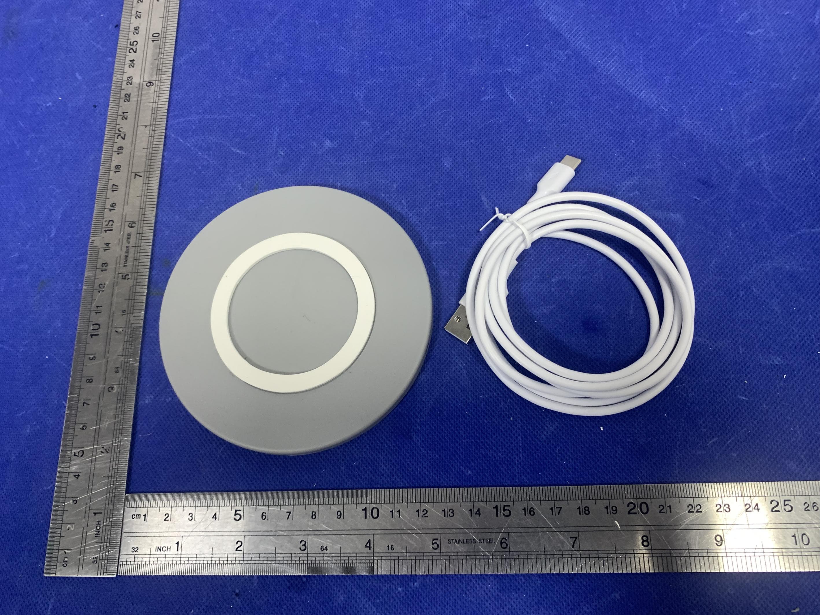
Click to zoom
Application Details
- Equipment Class
- DCD - Part 15 Low Power Transmitter Below 1705 kHz
- Date of Grant
- Jul 15, 2022
- Application Purpose
- Original Equipment
- Date of Application
- Jul 15, 2022
- Equipment Note
- Wireless charger
- Frequency Range
- 0.14720000 - 0.14720000
- Country
- China
Documents & Files
Document Text
Text extracted from the exhibit documents filed with the FCC. Open a document above to read the original.
Users Manual
Instructions for Us e Wireless Charger Wireless Charger Instructions for UseEN | 2 Content 1. General 4 2. Intended Use 4 3. Delivery Scope 4 4. Important Safety Instructions 4 5. Start-up 6 6. Technical Data 8 7. Exclusion of Liability 9 8. Warranty 9 9. Declaration of Conformity 9 10. Used Symbols and Icons 10 Wireless Charger Instructions for UseEN | 3 1. General The Wireless Charger is an inductive charging station. Please read the instructions carefully before use. 2. Intended Use This product is intended for wireless charging. 3. Delivery Scope • Wireless Charger • USB cable • Instructions for Use (digital) 4. Important Safety Instructions 1. Do not use the wireless charger for anything other than its intended use. 2. Do not use the wireless charger if it has visible damages, in very hot, humid or corrosive environments to avoid circuit damage and leakage. It should only be stored and transported under the conditions defined in these instructions. 3. Do not immerse in liquids and do not handle the wireless charger, USB cable or power adapter with wet hands. 4. Place the wireless charger on a sturdy and flat surface during charging. 5. Do not place too close to magnetic stripe or chip cards (ID cards, bank cards, etc.) to avoid magnetic defects. 6. Please keep a distance of at least 20 cm between implantable medical devices (pacemaker, implantable cochlear device, etc.) and the wireless Wireless Charger Instructions for UseEN | 4 charger to avoid possible interference with the medical device. Consult a physician before using the wireless charger. 7. Keep the wireless charger out of the reach of children. 8. The wireless charger is designed for indoor use only. 9. To protect the wireless charger against contamination and damage keep it closed and away from children, dust, sunlight, moisture, pets and vermin. 10. Please do not use water or chemical substances to clean the wireless charger. Please only use a dry cloth. 11. It is normal for the wireless charger to generate heat during use. Do not cover it with other objects during use. 12. The power socket must be next to the wireless charger and easily accessible. When you position the device, pay attention that nobody steps on the cable or trips over it. Do not put objects on the cable. 13. Do not open the wireless charger. Doing so may result in a life-threatening electric shock. It does not contain any parts that require maintenance. 14. In the case of a defect please contact your local distributor. Any attempt to repair the device will void the warranty. Wireless Charger Instructions for UseEN | 5 5. Start-up USB Type-C 1 2 1. Connect the power adapter to a power socket. The green indicator on the side of the wireless charger will glow solid green to indicate that a power connection is established. 2. Connect USB-A end of the supplied cable to a power adapter with at least 2 A output. Output: 5V, 2A Wireless Charger Instructions for UseEN | 6 3. Connect USB-C end of the cable to the wireless charger. 4. When power is supplied to the wireless charger, the LED will turn on. Note: Please make sure that you use a power adapter with an output of 9V DC @ 1.8A or 5V DC @ 2A. The power adapter is not part of the scope of delivery. USB Type-C USB Type-C 2 1 147.2kHz Wireless Charger Instructions for UseEN | 7 1. Place the device centered on top of the wireless charger 2. When the LED of the wireless charger turns off, charging is in progress. Note: If the LED of the wireless charger flashes, an error has occurred. In this case, please remove all objects from the wireless charger and place the device on the wireless charger again. Attention • Make sure that the wireless charger is connected to a working power socket. • Make sure that you use a power adapter with an output of 9V DC @ 1.8A or 5V DC @ 2A. • Make sure that the device is in the center of the wireless charger. • Make sure that there are no other objects on the wireless charger. • Make sure to unplug the wireless charger from the power supply when not in use. 6. Technical Data Product nameWireless Charger ModelHW01 Input portUSB Type-C InputDC 9 V 1.8 A, 5 V 2 A Output5 V – 5 W max. / 9 V – 10 W max. Frequency band Dimensions (diameter/height)116 mm / 6.3 mm Charging distance≤ 10 mm Power conversion≥ 75% Wireless Charger Instructions for UseEN | 8 Status displayLED Temperature range0°C to 35°C / 32°F to 95°F Relative humidity15 % to 85 % IP classification42 7. Exclusion of Liability The firmware and/or hardware may be changed at any time without prior notice. For this reason, it is possible that parts of these instructions, technical data and images in this documentation differ slightly from the product in your possession. All points described in these instructions only serve the purpose of clarification and must not inevitably correspond to a certain situation. No legal claims can be derived from these instructions. 8. Warranty The wireless charger has a 2-year warranty. The warranty applies only to material and production defects. Please understand that we cannot provide warranty service in the following cases: • Non-compliance with the instructions for use • Abusive or improper handling, installation or use • Damage, scratches or wear • Unauthorized modifications, opening of the housing, modifications or repairs • Damage caused by other devices, force majeure or transport Wireless Charger Instructions for UseEN | 9 9. Declaration of Conformity www.healyworld.net/doc/declaration/hw01 10. Used Symbols and Icons In conformity with European legislation Electronic waste – do not dispose. Recycle acc. to local regulations or contact your authorized dealer or the manufacturer. US Federal Communications Commission Certifica- tion Recycling Compliance with the Directive on the restriction of the use of certain hazardous substances in electrical and electronic equipment NCC Certification Taiwan for radio technologies Korean product certification MIC Certification: Radio product market app…
Text truncated - open the document above for the full version.
Attestation Statements
ShenzhenInputTechnologyCo.,Ltd. ModelDifference Productdescription:Wirelesscharger Modelname:HW01 WT-C23F,WT-C11F,WT-C8F,WT-C13F,WT-C19F,WT-26F,WT-C28F,WT- C8F,WT-Q3,WT-Q6 TradeName:N/A FCCID:2A7PX-HW01 AllthemodelarethesamecircuitandRFmodule,onlyformodelname. Regards Sincerely Client’ssignature: Client’sname/title:Ernestchan(N/A) Contactinformation/address:Floor2,Building1,BaoliIndustrialZone,Longgang District,Shenzhen,GuangdongProvince,China
Cover Letter(s)
C5266091_X8_Ed.1 1/1 LetterofAuthorization <ShenzhenInputTechnologyCo.,Ltd.> Company:ShenzhenInputTechnologyCo.,Ltd. Address:Floor2,Building1,BaoliIndustrialZone,Longgang District,Shenzhen,GuangdongProvince,China ProductName:Wirelesscharger ModelNumber:HW01 WT-C23F,WT-C11F,WT-C8F,WT-C13F,WT-C19F,WT-26F, WT-C28F,WT-C8F,WT-Q3,WT-Q6 FCCIdentifier:2A7PX-HW01 WeauthorizeLGAITechnologicalCenterS.A.,RondadelaFontdelCarme,s/n, 08193Bellaterra,Spain,toactonourbehalfonallmattersconcerningthe abovenamedequipment. AnyindividualwithinLGAITechnologicalCenterS.A.isauthorizedtoactonour behalfandtakeactionontheapplication. WedeclarethatauthorizeLGAITechnologicalCenterS.A.,RondadelaFontdel Carme,s/n,08193Bellaterra,Spain,isallowedtoforwardallinformation relatedtotheapprovalprojecttotheFederalCommunicationCommissionand todiscussanyissuesconcerningtheapprovalapplication.Anyandallacts carriedoutbyLGAITechnologicalCenterS.A.onourbehalfshallhavethe sameeffectasactsofourown. Name:ErnestchanDate:2022-07-07 Title:N/A Signatureofapplicant:
Cover Letter(s)
C5266091_X10_Ed.1 1/1 <ShenzhenInputTechnologyCo.,Ltd.> OfficeofEngineeringTechnology FederalCommunicationsCommission 7435OaklandMillsRoad Columbia,MD21046 Date:2022-07-07 Subject:RequestforConfidentiality FCCID:2A7PX-HW01 ToWhomItMayConcern, PursuanttotheprovisionsofSections0.457and0.459ofCommission'srules (47CFR0.457,0.459),wearerequestingtheCommissiontowithholdthefollowing attachment(s)asconfidentialdocumentfrompublicdisclosure. ExhibitsLong-Term Confidentiality Short-Term Confidentiality IDLabel/LocationNoNo AttestationStatementNoNo ExternalPhotosNo BlockDiagram Schematics TestReportNoNo TestSetupPhotosNo User’sManual InternalPhotos PartsList/TuneUp RFExposureInfo OperationalDescription CoverLetter(s)NoNo SDRSoftware/SecurityInfoNo Abovementioneddocumentcontainsdetailedsystemandequipmentdescriptionare consideredasproprietaryinformationinoperationoftheequipment.Thepublic disclosureofabovedocumentsmightbeharmfultoourcompanyandwouldgive competitoranunfairadvantageinthemarket. Itisourunderstandingthatallmeasurementtestreports,FCCIDlabelformatand correspondentduringcertificationreviewprocesscannotbegrantedasconfidential documentsandthoseinformationwillbeavailableforpublicreviewoncethegrantof equipmentauthorizationisissued. Sincerely, Signature: Name:Ernestchan Title:N/A
External Photos
EUTPHOTO(ExternalPhotos)
ID Label/Location Info
Labelandlabellocation Wirelesscharger FCCID:2A7PX-HW01
Internal Photos
EUTPHOTO(InternalPhotos) Coil1 ※※※※※ENDOFREPORT※※※※※
RF Exposure Info
FCCID:2A7PX-HW01 ProductName:Wirelesscharger ProductModelNo.:HW01 TestAuxiliary:Phone AuxiliaryModelNo.:ZKT-01 TransmittingmodeKeeptheEUTincontinuouslywirelesschargingmode Powersupply:Input:DC9V1.8AorDC5V2A Output:5V/5W(MAX),9V/10W(MAX) TestDescription:PhoneBattery>98%,=50%and<1%aretested,andtheworstis<1%. TestModes: Mode1AC/DCAdapter(9V/1.8A)+EUT+PhoneRecord Mode2AC/DCAdapter(5V/2A)+EUT+Phone Note:Alltestmodeswerepre-tested,butweonlyrecordedtheworstcaseinthisreport. RFExposureEvaluation 1MeasuringStandard KDB680106RFExposureWirelessChargingAppsv03r01 2Requirements Accordingtotheitem5ofKDB680106v03r01: Inductivewirelesspowertransferapplicationsthatmeetallofthefollowingrequirementsareexcludedfrom submittinganRFexposureevaluation. (1)Powertransferfrequencyislessthan1MHz. (2)Outputpowerfromeachprimarycoilislessthanorequalto15watts. (3)Thesystemmayconsistofmorethanonesourceprimarycoils,chargingoneormoreclients.Ifmorethan oneprimarycoilispresent,thecoilpairsmaybepoweredonatthesametime. (4)Clientdeviceisplaceddirectlyincontactwiththetransmitter. (5)Mobileexposureconditionsonly(portableexposureconditionsarenotcoveredbythisexclusion). (6)TheaggregateH-fieldstrengthsanywhereatorbeyond15cmsurroundingthedevice,and20cmaway fromthesurfacefromallcoilsthatbydesigncansimultaneouslytransmit,andwhilethosecoilsare simultaneouslyenergized,aredemonstratedtobelessthan50%oftheapplicableMPElimit. Remark:Meetalltheaboverequirements. Limits Thecriterialistedinthefollowingtableshallbeusedtoevaluatetheenvironmentimpactofhumanexposure toradiofrequency(RF)radiationasspecifiedin1.1307(b) LimitsforMaximumPermissibleExposure(MPE) 3TestSetup 4TestProcedure 1)TheRFexposuretestwasperformedinanechoicchamber. 2)Themeasurementprobewasplacedattestdistance(15cmfromallsidesand20cmfromthetop)whichis betweentheedgeofthechargerandthegeometriccenterofprobe. 3)Thehighestemissionlevelwasrecordedandcomparedwithlimitassoonasmeasurementofeachpoints (A,B,C,D,E)werecompleted. 4)TheEUTwasmeasuredaccordingtothedictatesofKDB680106v03r01. Remark:TheEUT’stestpositionA,B,C,DandEisvalidfortheEandHfieldmeasurements. 5TestInstrumentslist TestEquipmentManufacturerModelNo.SN. Cal.Date (mm-dd-yy) Cal.Duedate (mm-dd-yy) ExposureLevelTesterNardaELT-400N-0231June.262021June.252022 Magneticfieldprobe 100cm 2 NardaELTprobe100cm 2 M0675June.262021June.252022 IsotropicElectricfield probe NardaEP-601611WX70332June.262021June.252022 6TestResult E-FiledStrengthat15cmfromtheedgessurroundingtheEUT(V/m) FrequencyRange (MHz) Test PositionA Test PositionB Test PositionC Test PositionD Limits (V/m) 0.14720.760.740.750.74614 E-FiledStrengthat20cmfromthetopoftheEUT(V/m) FrequencyRange (MHz) Test PositionE Limits (V/m) 0.14720.75614 H-FiledStrengthat15cmfromtheedgessurroundingtheEUT(A/m) FrequencyRange (MHz) Test PositionA Test PositionB Test PositionC Test PositionD Limits (A/m) 0.14720.160.140.140.151.63 H-FiledStrengthat20cmfromthetopoftheEUT(A/m) FrequencyRange (MHz) Test PositionE Limits (A/m) 0.14720.151.64 7TestSet-upPhoto
Test Report
ProjectNo.:ZKT-2206214256E Page 1 of 22 FCCTESTREPORT FCCID:2A7PX-HW01 ReportNumber. .................................. :ZKT-2206214256E DateofTest ....................................................... : Jun.21,2022toJul.01,2022 Dateofissue.........................................: Jul.01,2022 Totalnumberofpages..........................22 TestResult .......................................... : PASS TestingLaboratory............................: ShenzhenZKTTechnologyCo.,Ltd. Address ............................................... : 1/F,No.101,BuildingB,No.6,TangweiCommunityIndustrial Avenue,FuhaiStreet,Bao'anDistrict,Shenzhen,China Applicant'sname.............................: ShenzhenInputTechnologyCo.,Ltd. Address...............................................: Floor2,Building1,BaoliIndustrialZone,Longgang District,Shenzhen,GuangdongProvince,China Manufacturer'sname......................: ShenzhenInputTechnologyCo.,Ltd. Address...............................................: Floor2,Building1,BaoliIndustrialZone,Longgang District,Shenzhen,GuangdongProvince,China Testspecification: Standard ................................................ :FCCCFRTitle47Part15SubpartC Testprocedure.....................................: / Non-standardtestmethod ................ :N/A TestReportFormNo........................: TRF-EL-107_V0 TestReportForm(s)Originator.....: ZKTTesting MasterTRF........................................: Dated:2020-01-06 ThisdevicedescribedabovehasbeentestedbyZKT,andthetestresultsshowthattheequipmentunder test(EUT)isincompliancewiththeFCCrequirements.Anditisapplicableonlytothetestedsample identifiedinthereport. Thisreportshallnotbereproducedexceptinfull,withoutthewrittenapprovalofZKT,thisdocumentmay bealteredorrevisedbyZKT,personalonly,andshallbenotedintherevisionofthedocument. Productname.....................................:Wirelesscharger Trademark...........................................: N/A Model/Typereference ......................... : HW01 WT-C23F,WT-C11F,WT-C8F,WT-C13F,WT-C19F,WT-26F, WT-C28F,WT-Q3,WT-Q6 Ratings .................................................. : Input:DC9V1.8AorDC5V2A Output:5V/5W(MAX),9V/10W(MAX) ProjectNo.:ZKT-2206214256E Page 2 of 22 Testingprocedureandtestinglocation: TestingLaboratory ....................................... :ShenzhenZKTTechnologyCo.,Ltd. Address ............................................................ :1/F,No.101,BuildingB,No.6,TangweiCommunity IndustrialAvenue,FuhaiStreet,Bao'anDistrict, Shenzhen,China JimLiu Testedby(name+signature).......................: JacksonFang Reviewer(name+signature) ....................... : LakeXie Approved(name+signature) ....................... : ProjectNo.:ZKT-2206214256E Page 3 of 22 TABLEOFCONTENTS 1.VERSION.......................................................................................................................................4 2.TESTSUMMARY........................................................................................................................5 2.1TESTFACILITY....................................................................................................................................6 2.2MEASUREMENTUNCERTAINTY....................................................................................................6 3.GENERALINFORMATION......................................................................................................7 3.1GENERALDESCRIPTIONOFEUT..................................................................................................7 3.2Testmode..............................................................................................................................................7 3.3BlockDiagramofEUTConfiguration................................................................................................7 3.4TestConditions.....................................................................................................................................8 3.5DescriptionOfSupportUnits(ConductedMode)............................................................................8 3.6EQUIPMENTSLISTFORALLTESTITEMS..................................................................................9 4.CONDUCTEDEMISSIONTEST............................................................................................10 4.1CONDUCTEDEMISSIONMEASUREMENT................................................................................10 4.1.1POWERLINECONDUCTEDEMISSIONLimits........................................................................10 4.1.2TESTPROCEDURE.......................................................................................................................10 4.1.3DEVIATIONFROMTESTSTANDARD.......................................................................................10 4.1.4TESTSETUP...................................................................................................................................11 4.1.5EUTOPERATINGCONDITIONS.................................................................................................11 4.1.6TestResult.......................................................................................................................................11 5.RADIATEDEMISSIONMEASUREMENT............................................................................14 5.1RadiatedEmissionLimits..................................................................................................................14 5.2AnechoicChamberTestSetupDiagram........................................................................................15 5.3TestProcedure....................................................................................................................................15 5.4DEVIATIONFROMTESTSTANDARD..........................................................................................15 5.5TestResult.............................................................................…
Text truncated - open the document above for the full version.
Test Setup Photos
EUTTESTPHOTO
Contact Information
Applicant
Ernest chan
Technical Contact
Non-Technical Contact
Shenzhen ZKT Technology Co., Ltd.Lake xie
[email protected]0086-400 000 9970
Test Firm
Shenzhen ZKT Technology Co., Ltd.Lake Xie
[email protected]0086-13620010775
Technical Specifications
| # | Rule Parts | Frequency Range | Power Output |
|---|---|---|---|
| 1 | 15C | 0.1472 MHz - 0.1472 MHz | - |