2A7UPVJ4Portable Industrial Borescope
Seneca Enterprises LLC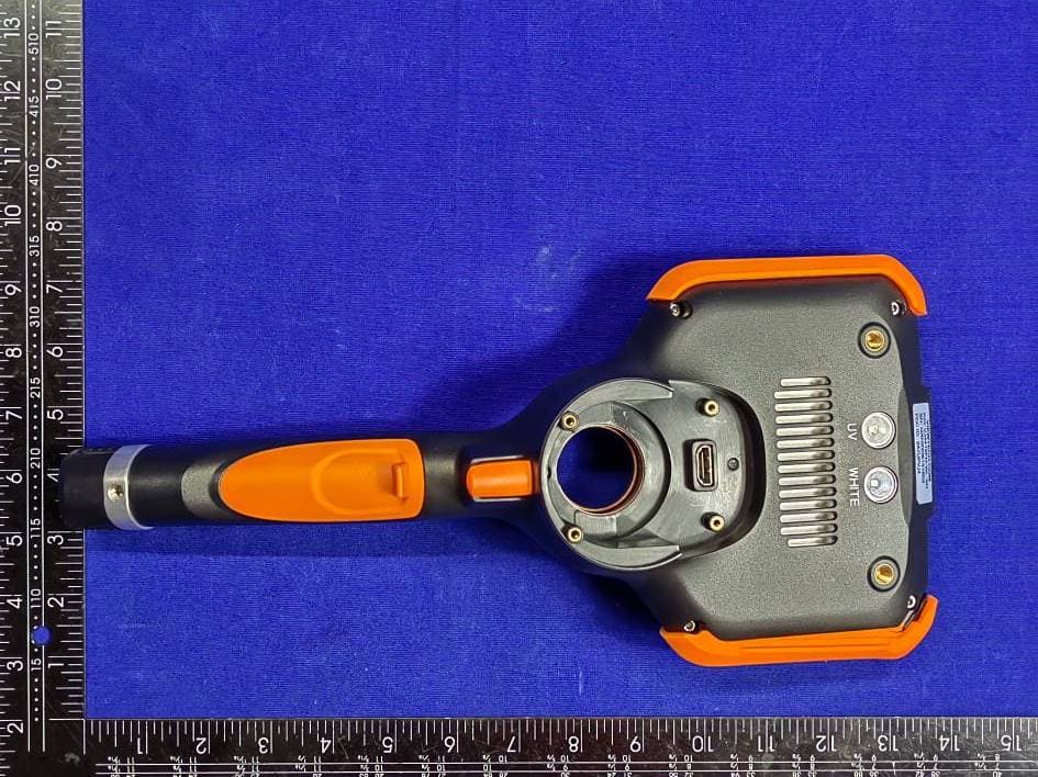
Click to zoom
Application Details
- Equipment Class
- DTS - Digital Transmission System
- Date of Grant
- Sep 27, 2022
- Application Purpose
- Original Equipment
- Date of Application
- Sep 26, 2022
- Equipment Note
- Portable Industrial Borescope
- Frequency Range
- 2412.00000000 - 2462.00000000
- Company
- Seneca Enterprises LLC
- Country
- United States
Documents & Files
Document Text
Text extracted from the exhibit documents filed with the FCC. Open a document above to read the original.
Users Manual
MECHANICAL ARTICULATING VIDEO BORESCOPE USER MANUAL VJ-4 TABLE OF CONTENTS I USER NOTICE 3 II PRODUCT SPECIFICATIONS 6 III PACKING LIST 8 IV PRODUCT OVERVIEW 9 V PART NAMES AND FUNCTIONS 10 VI PREPARATIONS 11 6.1 The Case 11 Removing The VJ-4 From The Case 11 6.2 Power Supply Preparations 11 Removing Battery Compartment 11 Opening / Loading The Battery Compartment 12 External Charging 13 VII MENU OPERATIONS & FUNCTIONS 14 7.1 Button Positions 14 7.2 Button Functions 15 7.3 Overview of Menu Functions 16 Menu Functions 16 LED Brightness 18 Screen Brightness 18 Display Ratio 18 Distance 18 Grid Measurement 20 Image Browsing 20 Zoom Function 20 Image Rotation and Mirror 21 Negative Color 21 Image Freeze 21 White Balance 22 7.4 System Settings Menu 22 Language 23 Date and Time 23 Video Format 23 Image Format 23 Folders 24 SD Card Management 26 Update Software 26 Hide Icons Delay 26 Annotation and Review Settings 27 Auto Shut Down Setting 30 WiFi Setting 30 Camera Temperature Setting 31 USB Mode Setting 32 About 32 TABLE OF CONTENTS CONT.. VIII BASIC OPERATIONS 33 8.1 Initial Checks 33 8.2 Turning On / Off 33 8.3 Turning White / UV Flashlight On / Off 33 8.4 Inserting The Insertion Tube Into Machinery or Equipment 34 Extracting The Insertion Tube 35 8.5 Recording Images 35 Loading The SD Card 35 Taking Still Images 36 Recording Video 36 8.6 Image Playback 36 Multi-Image View 36 Full Screen View 36 8.7 Deleting Images and Videos 37 Deleting Individual Images / Videos 37 Deleting All Images / Videos 38 8.8 System Settings Image Review and Editing 39 Image Review Icons 39 Image Editing Icon 40 Editing Individual Images 41 IX STORAGE AND MAINTENANCE 46 9.1 Cleaning 46 Cleaning The Insertion Tube 46 Cleaning the OLED Touch Screen 46 Cleaning the Base Unit 46 9.2 Repacking 46 9.3 Storage 46 X TROUBLESHOOTING 47 10.1 Troubleshooting Guidelines 47 10.2 Repair 47 PRODUCT WARRANTY & REPAIRS 48 CERTIFICATIONS 49 NOTES 50 2 3 USER NOTICE Please read this user manual carefully before operation. WARNING • Do not use or store in a place with explosives, a strong magnetic field or combustible gas. • Unauthorized dismantling or modification of this borescope voids the warranty. • Make sure the power is turned off before putting the instrument into the carrying case. • Never touch the camera / LED module during or immediately after use. Contact may cause burns. • Do not look directly at the light from the end of the insertion tube. It is extremely bright and can cause eye damage. • If any abnormality is noticed during operation, stop using and turn off the borescope immediately. ATTENTION • ONLY USE this borescope within the approved operating temperature range. • DO NOT use sharp objects or strong force when touching or tapping the OLED display. Too much force or using an object besides the provided stylus or fingertip could damage the screen. • DO NOT over-torque, crease, twist or fold the insertion tube. Doing so could damage the articulation control wire assemblies and / or electrical wiring. • ONLY USE the power adapter provided by ViewTech. • DO NOT yank or attempt to forcefully remove the insertion tube if it becomes stuck inside the equipment being borescoped. When extracting the insertion tube from the inspection area, be sure that the bending section (distal tip of the insertion tube) is straight. Use the joystick to remove any angle before attempting removal. If the insertion tube becomes stuck during removal, gently rotate the joystick until it becomes free again. • AFTER USE, center the joystick in order to straighten the bending section prior to storage. The borescope should always be stored with the bending section straight (do not force the bending section with your fingers – always use the joystick to adjust and straighten the bending angle.) I 4 • NOTE the following regarding the tip of the insertion tube (bending section and camera module), which is the most delicate part of this video borescope. • DO NOT impact the tip of the insertion tube while inserting or maneuvering inside the equipment being borescoped. • ONLY manipulate the joystick gently. Rapid movement of the joystick while borescoping may cause abrupt impact with the machinery and result in damage to the camera module or articulation. • ONLY USE the recommended alcohol solution when the lens is dirty or greasy and needs to be cleaned. • DO NOT force the joystick! If there is unusual resistance to joystick movement while conducting an inspection, it is because there is physical resistance inside the inspection area. Trying to force the joystick in this situation will result in damage to the articulation control wires, the joystick assembly or to the equipment being inspected. • DO NOT impact, press with excessive force or scratch the OLED display. • DO NOT cover the unit with a plastic bag or other similar protective covering during use. It may cause the unit to overheat and damage the internal circuitry. • DO NOT use or store the borescope in a high temperature, high humidity or high radiation environment. BATTERIES AND BATTERY CHARGING Follow the instructions below for battery care and proper charging, to prevent leakage, overheating, smoke, explosion, electric shock and burns. DANGER 1. Only use batteries and chargers specially designed for this borescope: 18650B battery with PCB-protection (button top). 2. Be sure the batteries are placed into the chamber in the correct direction (+ /–). 3. Do not carry or store the batteries where they may collide with metal objects. 4. Always keep the batteries away from fire or other sources of intense heat, as it could cause an explosion. 5. Do not attempt to open or modify batteries, as this could lead to an explosion or fire. 6. Do not immerse the batteries in liquid of any kind. 7. Do not charge the batteries near an open flame, as it could lead to an explosion or fire. 8. Do not drop, puncture, impact or apply pressure to the batteries as it could lead to an explosion or fire. 5 WARNING…
Text truncated - open the document above for the full version.
Users Manual
38 8.7.2 DELETING ALL IMAGES / VIDEOS While in the Folder Management setting, by touching any folder and then selecting the Edit icon at the top right corner, a user is able to select all images and videos for deletion by touching Select All located at the bottom left corner. After the selection is complete, touch delete to remove all images and videos. A prompt will be displayed noting “File cannot be restored after being deleted!”. Select OK to confirm or Cancel to exit. REMINDER All Images and Video can be viewed, organized, renamed and deleted by removing the SD card (8.5.1) from the VJ-4 Borescope and using the supplied SD card reader with your computer. Fig. 8-11 Selecting and deleting individual images and videos while in the Folder Management setting Fig. 8-12 Prompt displayed to confirm deletion of all images and videos selected 39 8.8 SYSTEM SETTINGS IMAGE REVIEW AND EDITING 8.8.1 IMAGE REVIEW ICONS Zoom In Zoom in on photos Zoom OutZoom out on photos Previous Image Move to the previous image Next Image Move to the next image Delete Image Delete the current image Enter Image Editing Mode Enter editing mode Rename The Current Image To rename an image or video file name Return To Previous Screen Go back to previous screen 40 8.8.2 IMAGE EDITING ICON Draw Icon Select to draw or write free hand on an image Arrow Icon Select to add arrow icons on an image Text Icon Select to type text on an image Reference Measurement Used to reference measurement Save Image Save image with changes that have been made Settings Icon Change the font size, line size, font color, curve color or arrow color. Undo Changes Revert the image prior to any changes being made Return To Previous Screen Go back to previous screen 41 8.8.3 EDITING INDIVIDUAL IMAGES Fig. 8 -13 Enter Image Editing Mode When viewing an image, by selecting the Enter Image Editing Mode icon users are able to view all image editing options. Once in Image Editing Mode, the Draw icon allows users to draw or write free hand on an image. Fig. 8-14 The Draw Icon 42 8.8.3 EDITING INDIVIDUAL IMAGES Fig. 8-16 The Text Icon and Keyboard When the Text icon is selected, first touch the screen to locate the placement of the annotation. Next, type the text to be displayed and touch OK. Touching the Save icon saves all changes that have been made to the image. Fig. 8-15 The Arrow Icon The Arrow icon is used to add arrows to an image. 43 8.8.3 EDITING INDIVIDUAL IMAGES CONTINUED Fig. 8-17 Text Displayed Fig. 8-18 Select an Image to Calculate Reference Measurement Once selecting an image to use in Reference Measurement mode, begin by tapping two points, from left to right, on the screen to indicate your measure- ment reference. 44 8.8.3 EDITING INDIVIDUAL IMAGES CONTINUED Fig. 8-19 The Red Line is the Reference Measurement After completing the reference line, a red line and the distance pixel value will appear. Next, tap two points to indicate the distance you would like to be measured. A green line and its pixel value will appear. Fig. 8-20 The Green Line is the Length to be Measured 45 8.8.3 EDITING INDIVIDUAL IMAGES CONTINUED Fig. 8-21 Input the Known Length of Measurement Fig. 8-22 Length to be Measured is Displayed After both a red reference line and green line to estimate measurement are completed, input a number for the known length of the reference. This is the actual length of the red reference line and can be measured in millimeters, centimeters or meters. Once the length of reference has been entered, lengths to be measured will display. 46 8.8.3 EDITING INDIVIDUAL IMAGES CONTINUED Fig. 8-23 Multiple Lengths Measured Fig. 8-24 Save Images Before Exiting Users can then estimate additional lengths to be measured, based on the original length of reference. Lastly, be sure to save the image for measurement results to display. If you were to exit the image without saving, all measurement information will be removed. 47 8.8.3 EDITING INDIVIDUAL IMAGES CONTINUED Fig. 8-25 The Settings Icon screen where font size, line size, font color, line color and arrow color can be adjusted. 48 IX STORAGE AND MAINTENANCE 9.1 CLEANING CLEANING THE INSERTION TUBE 1. Wipe dirt, grease, grime and liquids from the insertion tube with a dust-free cloth. 2. Make sure that the insertion tube is completely dry before replacing the borescope back into the case. WARNING Do not store the borescope in a high temperature, high humidity or corrosive environment. CLEANING THE OLED TOUCH SCREEN If the OLED touch screen has fingerprints, grease or stains, wipe the screen with a dust-free cloth. CLEANING THE BASE UNIT Wipe the base unit with a dust-free cloth as needed. 9.2 REPACKING 1. Return the borescope to the case carefully in order to avoid unintentional damage to the insertion tube or camera / LED module. 2. Be sure that the joystick is in the center / neutral position and that the bending section is straight prior to inserting the borescope into the case. 3. When returning the borescope to the case, first carefully feed the insertion tube into the coil-wheel slot, then place the base unit into the case only after the insertion tube is fully inserted. 9.3 STORAGE Store at normal room temperature and humidity. Do not store with flammable materials, in direct sunlight or around strong magnetic fields. 49 X TROUBLESHOOTING 10.1 TROUBLESHOOTING GUIDELINES If malfunctions cannot be resolved by following the troubleshooting guidelines below, please contact ViewTech for more detailed troubleshooting instructions or to request a Return Merchandise Authorization (RMA) and repair ticket: MALFUNCTIONPOSSIBLE CAUSESPROPOSED MEASURES Unable to capture images or video No SD cardInstall the SD card correctly Still showing no SD card after insertion of SD card SD card is not inserted properly Re-insert the SD card into the slot Automatic shutdown Triggered by too high ambient temperature Stop using, allow unit to cool down and then restart Triggered by too low battery level Charge the bat…
Text truncated - open the document above for the full version.
Attestation Statements
Seneca Enterprises LLC Date: 2022-07-27 To: Federal Communications Commission 7435 Oakland Mills Road Columbia, MD FCC ID: 2A7UPVJ4 To Whom It May Concern: This letter is to ascertain that Seneca Enterprises LLC EUT:Portable Industrial Borescope MODEL No.: VJ4XXXYY-YY-YY (X=0-9, Y=A-Z) Has been the units used for conducting FCC compliance testing, the SDoC part will be tested by EMTEK (SHENZHEN) CO., LTD. If you have any question or concerns, pls. contact us. Sincerely, Client’s signature : Client’s name / title : Sean OConnor/GM Contact information / address: Seneca Enterprises LLC /1745 Barlow Street, Traverse City, Michigan, 49686, USA
Attestation Statements
Declaration on model difference We the undersigned hereby confirm that any of our production units bearing the following model numbers are identical in circuitry and electrical, mechanical and physical construction; only a difference for length of the pipeline between them; FCC ID: 2A7UPVJ4 Production name Trade name Model no. Portable Industrial Borescope VJ4XXXYY-YY-YY (X=0-9, Y=A-Z) Confirmed by Seneca Enterprises LLC Client’s name / title : Sean OConnor/GM Contact information / address: Seneca Enterprises LLC /1745 Barlow Street, Traverse City, Michigan, 49686, USA Date: 2022-07-27
Cover Letter(s)
Seneca Enterprises LLC 2022-9-20 Eurofins Electrical and Electronic Testing NA, Inc. 914 West Patapsco Avenue Baltimore, MD 21230 RE: CONFIDENTIALITY REQUEST FOR (Product Name: Portable Industrial Borescope Model Number: VJ4XXXYY-YY-YY (X=0-9, Y=A-Z) FCC ID: 2A7UPVJ4) To Whom It May Concern: This letter serves as an official request for confidentiality under sections 0.457 and 0.459 of CFR 47. We have requested that the (Block Diagram, Circuit Schematic, Operation Description) required to be submitted with this application be permanently withheld from public review. The above materials contain trade secrets and proprietary information not customarily released to the public. The public disclosure of these materials may be harmful to the applicant and provide unjustified benefits to its competitors. Please contact me if there is any information you may need. Sincerely, Sean OConnor/GM Date: 2022.9.20 Seneca Enterprises LLC
Cover Letter(s)
Seneca Enterprises LLC 2022-9-20 Eurofins Electrical and Electronic Testing NA, Inc. 914 West Patapsco Avenue Baltimore, MD 21230 RE: LETTER OF AGENT AUTHORIZATION To Whom It May Concern: We, the undersigned, hereby authorize EMTEK (SHENZHEN) CO., LTD. to act on our behalf in all matters relating to application for equipment authorization, including the signing of all documents relating to these matters. We also hereby certify that no party to the application authorized hereunder is subject to the denial of benefits, including FCC benefits, pursuant to Section 5301 of the Anti-Drug Abuse Act of 1988, 21 U.S.C.853(a). This agreement expires one year from the current date. Sincerely, Sean OConnor/GM Date: 2022.9.20 Seneca Enterprises LLC
ID Label/Location Info
Location
Internal Photos
Module Antenna
Parts List/Tune Up Info
承认书项目表 内容 页数 页码 NO. ( Number ( Page ( Contents ) ofPage ) Code ) 1 承认书封面(Spec Cover) 11 2 承认书项目表(Spec Item) 12 3 工程成品图(Dr awing) 13 4 电性测试报告(Test Reports) 14 5 S参数测试(S Parameter) 15 6 增益测试 (Gain Test) 16 7 8 9 10 --- 11--- 12 --- Manufacturer: Dongguan Mai Xun Electronics Co., LTD Address: No. 6, Daning Qilin East Road, Humen Town, Dongguan City 电性测试报告 TestReports Impedance500hmNominal ReturnLoss-10dBMax RadiationOmni-directional CableLoss2dB/mMax PolarizationLinear,Vertical AdmittedPower1W ConnectorIPEX PhysicalProperties AntennaMaterialFPC CableTypeO.D.1.13mm//130mm OperatingTemp. -10~+60 ̊C StorageTemp.-10~+70 ̊C SamplePhoto A.ElectricalCharacteristics Frequency 2400~2500MHz 4900~5900MHz S.W.R. <=2.0 @2400~2500MHz <=2.0@4900~5900MHz Tel:17084460528 S参数测试 SParameterTest AgilentE5071C Tel:17084460528 Product Number: MX F3511A-113B-130LX Product Name: Antenna 2. Characteristics and Reliability Test Test Items Test Condition and Procedure Requirements C1 S.W.R. Set DUT on Network Analyzer; make individual calibration to test Directive DUT specification C2 Antenna Gain Set DUT on Antenna Chamber; make individual calibration to test Directive DUT specification M1 Vibration MIL-STD-202G, 201A Amplitude: 0.03 inch (0.76mm); Freq: 10 to 55 Hz 3 directions; 2 hours for each direction 1. No Visual Damage 2. Frequency Tol.<= 5% M2 Random Drop Height: 1.5 Meter; 3 directions; 1 time for each direction 1. No parts separated 2. Frequency Tol.<= 5% M3 Solderability MIL-STD-202G, 210F, cond. A Solder iron: 350±10°C; Duration: 5 seconds 1. Mounted on PCB 2. No Visual Damage M4 Terminal- Pull Test MIL-STD-202G, 211A, cond. A Holding with individual specification; force applied to axis of terminal 1. Directive DUT specification 2. Frequency Tol.<= 5% M5 Terminal- Torque Test MIL-STD-202G, 211A, cond. E Holding with individual specification; applied clockwise and counterclockwise to the axis of terminal 1. Directive DUT specification 2. Frequency Tol.<= 5% M6 Dimension Inspection of dimension, color, material, package, surface process Directive DUT specification E1 Salt Spray MIL-STD-202G, 101E, cond. B Temp: 35°C; RH: >= 95%; NaCl solution: >= 5%; Time: 48 hours After 2 Hours Recovery 1. No Visual Damage 2. Frequency Tol.<= 5% E2 Humidity MIL-STD-202G, 103B, cond. B Temp: 40°C; RH: >= 95%; Time: 48 hours After 2 Hours Recovery 1. No Visual Damage 2. Frequency Tol.<= 5% E3 Thermal Shock 1 Cycle: - 40°C (30 minutes) to + 80°C (30 minutes) Cycles: 24 After 2 Hours Recovery 1. No Visual Damage 2. Frequency Tol.<= 5% E4 Life (High Temp.) MIL-STD-202G, 108A, cond. A Temp: 85°C; Time: 96 hours After 2 Hours Recovery 1. No Visual Damage 2. Frequency Tol.<= 5% Product Name: Antenna Product Number: MX F3511A-113B-130LX Page 5 Version: 1.0 Issue Date: 2011-03-28 3. Antenna - Radiation Pattern Test Data Testing Equipment Specification: Antenna Anechoic Chamber Dimension: 8 x 4 x 4 m Quite Zone: 600mm @1 GHz Isolation: >100dB @ 1 MHz ~ 10 GHz Testing Equipment: Agilent 5071B Received Antenna: 0.7 ~ 6.0 GHz for Gain Calibration Double Ridged Horn Antenna Product Name: Antenna Antenna - Radiation Pattern Test Data XY-PLANE 2400 MHz 2450 MHz 2500 MHz 5000 MHz 5500 MHz 5800 MHz Product Name: Antenna Antenna - Radiation Pattern Test Data XZ-PLANE 2400 MHz 2450 MHz 2500 MHz 5000 MHz 5500 MHz 5800 MHz Product Name: Antenna Antenna - Radiation Pattern Test Data XY-PLANE 2400 MHz 2450 MHz 2500 MHz 5000 MHz 5500 MHz 5800 MHz 2.98 3.35 2.92 3.06 2.42 2.36
RF Exposure Info
Report No. ENS2205180134W00202R Page 1 of 38 Ver.1.0 TEST REPORT Product Name : Portable Industrial Borescope Model Number : VJ4XXXYY-YY-YY (X=0-9, Y=A-Z) FCC ID : 2A7UPVJ4 Prepared for : Seneca Enterprises LLC Address : 1745 Barlow Street, Traverse City, Michigan, 49686, USA Prepared by : EMTEK (SHENZHEN) CO., LTD. Address : Bldg 69, Majialong Industry Zone, Nanshan District, Shenzhen, Guangdong, China Tel: (0755) 26954280 Fax: (0755) 26954282 Report Number : ENS2205180134W00202R Date(s) of Tests : July 8, 2022 to July 10, 2022 Date of Issue : July 11, 2022 Report No. ENS2205180134W00202R Page 2 of 38 Ver.1.0 TABLE OF CONTENTS 1. TEST RESULT CERTIFICATION ............................................................................................................................ 4 2. Description of Equipment Under Test .................................................................................................................. 6 3. SAR Measurement System .................................................................................................................................... 7 3.1 Definition of SpecificAbsorptionRate (SAR) ..................................................................................................... 7 3.2 SPEAG DASY System ..................................................................................................................................... 7 3.2.1 Robot .................................................................................................................................................. 8 3.2.2 Probes ................................................................................................................................................ 9 3.2.3 Data Acquisition Electronics (DAE) .................................................................................................... 9 3.2.4 Phantoms ......................................................................................................................................... 10 3.2.5 Device Holder ................................................................................................................................... 11 3.2.6 System Validation Dipoles ................................................................................................................ 11 3.2.7 Tissue Simulating Liquids ................................................................................................................. 12 3.3 SAR System Verification ................................................................................................................................ 14 3.4 SAR Measurement Procedure ....................................................................................................................... 15 3.4.1 Area & Zoom Scan Procedure ......................................................................................................... 15 3.4.2 VolumeScan Procedure .................................................................................................................... 15 3.4.3 Power Drift Monitoring ...................................................................................................................... 16 3.4.4 Spatial Peak SAR Evaluation ........................................................................................................... 16 3.4.5 SAR Averaged Methods ................................................................................................................... 16 4. SARMeasurement Evaluation .............................................................................................................................. 17 4.1 Applicable Standards ..................................................................................................................................... 17 4.2 EUT Configuration and Setting ...................................................................................................................... 17 4.3 EUT Testing Position ...................................................................................................................................... 19 4.3.1 Body Exposure Conditions ............................................................................................................... 19 4.3.2 SAR Test Exclusion Evaluations ...................................................................................................... 21 4.4 Tissue Verification .......................................................................................................................................... 22 4.5 System Validation ........................................................................................................................................... 22 4.6 System Verification ......................................................................................................................................... 23 4.7 Maximum Output Power ................................................................................................................................. 24 4.7.1 Maximum Conducted Power ............................................................................................................ 24 4.7.2 Measured Conducted Power Result ................................................................................................ 24 4.8 SAR Testing Results ....................................................................................................................................... 25 4.8.1 SAR Test Reduction Considerations ................................................................................................ 25 4.8.2 SAR Results for Body Exposure Condition ...................................................................................... 26 4.8.3 2.4GHz 802.11g/n OFDM SAR Test Exclusion Consideration: ........................................................ 27 4.8.4 SAR Measurement Variability .......…
Text truncated - open the document above for the full version.
Test Report
Report No. ENS2205180134W00201R Page 1 of 63 Ver.1.0 TEST REPORT Product Name : Portable Industrial Borescope Test Model : VJ4415FM-WL-XH FCC ID : 2A7UPVJ4 Prepared for : Seneca Enterprises LLC Address : 1745 Barlow Street, Traverse City, Michigan, 49686, USA Prepared by : EMTEK (SHENZHEN) CO., LTD. Address : Building 69, Majialong Industry Zone, Nanshan District, Shenzhen, Guangdong, China Tel: (0755) 26954280 Fax: (0755) 26954282 Report Number : ENS2205180134W00201R Date(s) of Tests : June 14, 2022 to July 14, 2022 Date of issue : July 14, 2022 $二维码$ Report No. ENS2205180134W00201R Page 2 of 63 Ver.1.0 TABLE OF CONTENTS 1 TEST RESULT CERTIFICATION ........................................................................................................ 3 2 EUT TECHNICAL DESCRIPTION ...................................................................................................... 5 3 SUMMARY OF TEST RESULT ........................................................................................................... 6 4 TEST METHODOLOGY ...................................................................................................................... 7 4.1 GENERAL DESCRIPTION OF APPLIED STANDARDS .............................................................. 7 4.2 MEASUREMENT EQUIPMENT USED ........................................................................................ 7 4.3 DESCRIPTION OF TEST MODES ............................................................................................... 8 5 FACILITIES AND ACCREDITATIONS ................................................................................................ 9 5.1 FACILITIES .................................................................................................................................. 9 5.2 EQUIPMENT ................................................................................................................................ 9 5.3 LABORATORY ACCREDITATIONS AND LISTINGS ................................................................... 9 6 TEST SYSTEM UNCERTAINTY ....................................................................................................... 10 7 SETUP OF EQUIPMENT UNDER TEST ........................................................................................... 11 7.1 RADIO FREQUENCY TEST SETUP 1 ........................................................................................ 11 7.2 RADIO FREQUENCY TEST SETUP 2 ........................................................................................ 11 7.3 CONDUCTED EMISSION TEST SETUP ................................................................................... 14 7.4 BLOCK DIAGRAM CONFIGURATION OF TEST SYSTEM ....................................................... 15 7.5 SUPPORT EQUIPMENT ............................................................................................................ 15 8 TEST REQUIREMENTS .................................................................................................................... 16 8.1 DTS 6DB BANDWIDTH .............................................................................................................. 16 8.2 DTS 99% BANDWIDTH ............................................................................................................. 22 8.3 MAXIMUM PEAK CONDUCTED OUTPUT POWER ................................................................. 28 8.4 MAXIMUM POWER SPECTRAL DENSITY ............................................................................... 34 8.5 UNWANTED EMISSIONS IN NON-RESTRICTED FREQUENCY BANDS ............................... 40 8.6 RADIATED SPURIOUS EMISSION ........................................................................................... 47 8.7 CONDUCTED EMISSION TEST ................................................................................................ 59 8.8 ANTENNA APPLICATION .......................................................................................................... 62 Report No. ENS2205180134W00201R Page 3 of 63 Ver.1.0 1 TEST RESULT CERTIFICATION Applicant : Seneca Enterprises LLC Address : 1745 Barlow Street, Traverse City, Michigan, 49686, USA Manufacturer : Shenzhen Yateks Co., Ltd Address : F11th, Block B, Building 3, Tian'an Cyber Park, Longgang District, Shenzhen, China EUT : Portable Industrial Borescope Test Model : VJ4415FM-WL-XH Trademark : Measurement Procedure Used: APPLICABLE STANDARDS STANDARD TEST RESULT FCC 47 CFR Part 2 , Subpart J FCC 47 CFR Part 15, Subpart C PASS IC RSS-GEN, Issue 5(04-2018)+A1(03-2019)+A2(02-2021) IC RSS-247 Issue 2(02-2017) PASS The above equipment was tested by EMTEK(SHENZHEN) CO., LTD. The test data, data evaluation, test procedures, and equipment configurations shown in this report were made in accordance with the procedures given in ANSI C63.10 (2013) and the energy emitted by the sample EUT tested as described in this report is in compliance with the requirements of FCC Rules Part 2, Part 15.247, IC RSS-247 Issue 2 and IC RSS-GEN, Issue 5. The test results of this report relate only to the tested sample identified in this report. Date of Test : June 14, 2022 to July 14, 2022 Prepared by : Una Yu /Editor Reviewer : Sevin Li /Supervisor Approve & Authorized Signer : Lisa Wang/Manager Report No. ENS2205180134W00201R Page 4 of 63 Ver.1.0 Modified History Version Report No. Revision Date Summary V1.0 ENS2205180134W00201R / Original Report Report No. ENS2205180134W00201R Page 5 of 63 Ver.1.0 2 EUT TECHNICAL DESCRIPTION Note:…
Text truncated - open the document above for the full version.
Contact Information
Applicant
Sean OConnor(GM)
Technical Contact
EMTEK (SHENZHEN) CO., LTD.Lisa Wang
[email protected]+86 755 26504659
Bldg 69,Majialong Industry Zone, · Shenzhen, Guangdong · China
Test Firm
EMTEK (Shenzhen) Co., Ltd.Lisa Wang
[email protected]86 755 26954280
Technical Specifications
| # | Rule Parts | Frequency Range | Power Output |
|---|---|---|---|
| 1 | 15C | 2.41 GHz - 2.46 GHz | 22.00 mW |