2A82LSPOT-V1Spot Mapper
Nova Labs, Inc.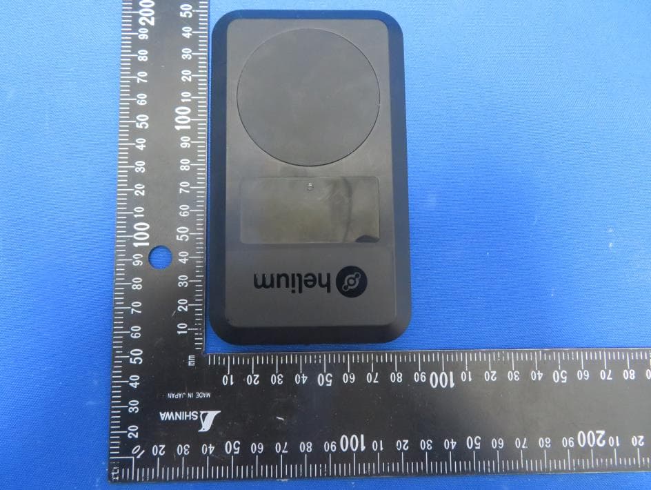
Click to zoom
Application Details
- Equipment Class
- DTS - Digital Transmission System
- Date of Grant
- Jan 16, 2023
- Application Purpose
- Original Equipment
- Date of Application
- Jan 16, 2023
- Equipment Note
- Spot Mapper
- Frequency Range
- 2412.00000000 - 2462.00000000
- Company
- Nova Labs, Inc.
- Country
- United States
Documents & Files
Document Text
Text extracted from the exhibit documents filed with the FCC. Open a document above to read the original.
Users Manual
Device Manual - Helium Mobile Spot™ Spot-US | Nova Labs, Inc Table of Contents Device Manual - Helium Mobile Spot1 Table of Contents1 Helium Mobile Spot2 What’s Inside the Box2 Set-Up2 Power On2 Downloading the Spot App3 Onboarding your Spot3 Spot Basics3 Settings3 Device Information4 Battery4 Understanding Spot’s status LED’s4 Power Off and Reset4 Mapping5 Positioning your Spot5 Mapping Basics5 Scanning5 Attaching5 Support5 Limited Warranty5 FCC Regulatory Information10 Helium Mobile Spot™ The Helium Mobile Spot is a mapping device that enables users to verify the Helium 5G Network and earn $MOBILE rewards via the dedicated“Spot App” What’s Inside the Box Included in the box for Helium Mobile Spot™ should be: ●1 Helium Mobile Spot Mapper (82.1 mm x 141.1 mm x 18.1 mm, 218.6 g) ●1 Charging Cable ●1 Paper Insert with a QR Code to the User Guide ●1 Warranty and FCC Compliance Pamphlet Set-Up Setting up your Spot device is simple. Before beginning the process, it is recommended to be prepared with: ●Internet connection via a Wi-Fi network. Note, you will need the login credentials to a Wi-Fi network to connect your Spot device. ●Bluetooth connection enabled on your mobile device Power On You can power on your Spot by holding down the button on the side of the device. Upon holding down this button, the LED lights on your device will turn white. View the diagram below. If Spot does not turn on right away, you may need to charge the battery by connecting your device to a USB-C power source with the provided charging cable. Downloading the Spot App The Spot App allows users to onboard their Spot device and map the Helium Network. The Spot App is available on Android and iOS. 1.The Spot App can be located in the Play Store on an Android device or the App Store on an iOS device. 2.Search for “Spot App”. 3.Download the Spot App to your device. 4.When the app has completed downloading, you are now ready to begin onboarding your Spot. Onboarding your Spot To onboard your Spot device using the “Spot App”, follow the instructions outlined within the app. These instructions outline the following steps in detail. 1.Open the Spot app on your mobile device. 2.Tap "Connect to Spot” 3.Enable Bluetooth on your mobile device to pair your Spot. 4.Follow the instructions in the app to power on your Spot device and pair to Bluetooth 5.Tap “Continue Set-Up” to begin connecting your device to Wi-Fi. 6.Follow the instructions in the app to successfully connect your Spot device to your Wi-Fi. This step is necessary for receiving over-the-air device updates on your Spot. Wi-Fi is not necessary for mapping. For more details regarding the in-app set-up process, please visit https://hellohelium.com/spot/getstarted. Spot Basics Settings You can locate important information regarding your Spot in the “Settings” menu of the Spot App. To navigate to “Settings”, tap on the 3 white lines to open up the Menu. Select “Settings” from the list of menu options. Device Information Device information can be found under the “Device Settings” section in “Settings” in the Spot App. The following information is available in this section: ●Unique Device Name ●Device Public Key ●Service Set Identifier (SSID) ●International Mobile Equipment Identity (IMEI) Battery Your Spot’s battery percentage can be found under “Device Settings” in the “Settings” menu. When fully charged, Spot’s battery can last up to 3 hours while actively mapping. Understanding Spot’s status LED’s The Spot has four status LEDs representing the current state of its modems: IoT, Mobile, Wi-Fi, and Bluetooth. These LEDs can be blue, green, red,or white. IoTBreathesGreen- LoraWAN is connected BlinksGreen- Sending data over LoraWAN MobileSolidGreen- Spot is scanning a hex SolidBlue- Spot is beginning an attach BlinksBlue- Attach is successful BlinksRed- Attach is unsuccessful Wi-FiBreathesGreen- Wi-Fi is connected BlinkRed- Wi-Fi is not connected, Error BluetoothSolidGreen- Bluetooth is enabled SolidRed- Bluetooth is disabled BlinksBlue- Spot is scanning for Bluetooth SolidBlue- Bluetooth is connected Power Off and Reset To power off your Spot using the device, hold down the side button for 2 seconds or until all lights blink blue. You can also power off your Spot by visiting “Settings” and scrolling to the bottom of the page. Tap on “Power Off Spot”. To reset your Spot, hold down the side button for 10 seconds. Continue to hold down this button as the lights turn blue. After 10 seconds, all lights will blink red and your Spot will reset. Mapping Positioning your Spot While mapping, ensure your Spot device is held in the upright position for optimum mapping. This position will have the Helium™ Roundel facing upwards. Mapping with your Spot Device on its side or face down will result in slow or inaccurate mapping. Spot is rated to operate between -20 and 50 ° C, sobeware of leaving it in direct sunlight or outdoors. Mapping Basics With your Spot device powered on and has been successfully onboarded to the Spot app, you are able to begin mapping. There are two events that Spot completes while mapping: scanning and attaching. Scanning Scanning occurs automatically when you begin mapping. Scans occur when your Spot passively “sniffs” the surrounding airwaves to locate Helium 5G coverage. Scans occur constantly and inform users of the presence of a Helium CBRS. Attaching When your Spot device has detected the Helium 5G Network, it will begin to “attach” to the cell. Attaches verify the coverage emitted from the radio and determine the quality of coverage via its signal strength For more information about mapping, visithttps://www.hellohelium.com/spot/getstarted. Support For any support inquiries, please [email protected]. Limited Warranty One-Year Limited Warranty - Summary The full terms of Nova’s One Year Limited Warranty for the Mobile Spot and detailed information on obtaining service are available athttps://hellohelium.com/spot/warranty. Nova One (1) Year Limited…
Text truncated - open the document above for the full version.
Cover Letter(s)
Nova Labs, Inc. Confidentiality Request Letter Federal Communications Commission Authorization and Evaluation Division FCC ID: 2A82LSPOT-V1 Pursuant to Sections 0.457 and 0.459 of the Commission’s Rules, we hereby request confidential treatment of information accompanying this application as outlined below: 1. Block Diagram 2. Schematics 3. Operational Description 4. Tune-up Procedure The above materials contain trade secrets and proprietary information not customarily released to the public. The public disclosure of these matters might be harmful to the applicant and provide unjustified benefits to its competitors. The applicant understands that pursuant to Rule 0.457, disclosure of this application and all accompanying documentation will not be made before the date of the Grant for this application. Sincerely, _________________ Name: Louis Thiery Title: Engineer Email: [email protected] Date: 2023-01-09 DocuSign Envelope ID: 9EF5592A-E130-4E2E-94CF-9FB56CCA1C1B
Cover Letter(s)
Nova Labs, Inc. Short Term Confidentiality Request Letter Federal Communications Commission Authorization and Evaluation Division FCC ID: 2A82LSPOT-V1 Pursuant to sections 0.457 and 0.459 of CFR 47 Commission’s policy and to avoid premature release of sensitive information prior to marketing or release of the product to the public, the applicant requests the following documents contained in this certification application be temporarily withheld from public disclosure for an initial period of 180 days: 1. External Photos 2. Internal Photos 3. Test Setup Photos 4. User Manual The above materials contain trade secrets and proprietary information not customarily released to the public. The public disclosure of these matters might be harmful to the applicant and provide unjustified benefits to its competitors. The applicant understands that pursuant to Rule 0.457, disclosure of this application and all accompanying documentation will not be made before the date of the Grant for this application. Sincerely, _________________ Name: Louis Thiery Title: Engineer Email: [email protected] Date: 2022-12-09 DocuSign Envelope ID: D9505F93-F45B-4432-981F-4DB05ABA3221
Cover Letter(s)
Nova Labs, Inc. Declaration of Authorization We Name: Nova Labs, Inc. Address: 2202 South Figueroa #408, Los Angeles, CA 90007, United States Declare that: Name Representative of agent: Marlin Chen Agent Company name: MRT Technology (Suzhou) Co., Ltd Address: D8 Building, Youxin Industrial Park, No.2 Tian'edang Rd., Wuzhong Economic Development Zone City: Suzhou Country: China is authorized to apply for Certification of the following product(s): Product: Spot Mapper FCC ID: 2A82LSPOT-V1 Model No.: Spot-US Sincerely, ________________ Name: Louis Thiery Title: Engineer Email: [email protected] Date: 2022-12-09 DocuSign Envelope ID: D9505F93-F45B-4432-981F-4DB05ABA3221
External Photos
Report No.: 2209RSU059-UE 1 of 3 EUT Photograph (1) EUT Photo (2) EUT Photo Report No.: 2209RSU059-UE 2 of 3 (3) EUT Photo (4) EUT Photo Report No.: 2209RSU059-UE 3 of 3 (5) EUT Photo (6) EUT Photo
ID Label/Location Info
Model:Spot-US SN: E1N22G61100000030 IMEI: 867648047007461 FCC ID: 2A82LSPOT-V1 Model:Spot-US SN: E1N22G61100000030 IMEI: 867648047007461 FCC ID: 2A82LSPOT-V1 54.6mm 26.1mm 1.8mm
Internal Photos
Report No.: 2209RSU059-UE 1 of 9 EUT Photograph (1) EUT Photo (2) EUT Photo Report No.: 2209RSU059-UE 2 of 9 (3) EUT Photo (4) EUT Photo Report No.: 2209RSU059-UE 3 of 9 (5) EUT Photo (6) EUT Photo Report No.: 2209RSU059-UE 4 of 9 (7) EUT Photo (8) EUT Photo Report No.: 2209RSU059-UE 5 of 9 (9) EUT Photo (10) EUT Photo Report No.: 2209RSU059-UE 6 of 9 (11) EUT Photo (12) EUT Photo Report No.: 2209RSU059-UE 7 of 9 (13) EUT Photo (14) EUT Photo Report No.: 2209RSU059-UE 8 of 9 (15) EUT Photo (16) EUT Photo Report No.: 2209RSU059-UE 9 of 9 (17) EUT Photo
RF Exposure Info
MRT Technology (Suzhou) Co., Ltd Report No.: 2209RSU059-U11 Phone: +86-512-66308358 Report Version: V02 Web: www.mrt-cert.com Issue Date: 2023-01-06 1 of 147 FCC ID: 2A82LSPOT-V1 Applicant: Nova Labs, Inc. Product: Spot Mapper Model No.: Spot-US Brand Name: Helium FCC Rule Part(s): FCC 47 CFR Part 2.1093 Result: Complies Test Date: 2022-10-25 ~ 2022-11-14 SAR MEASUREMENT REPORT Reviewed By: Sunny Sun Approved By: Robin Wu The test results relate only to the samples tested. This equipment has been shown to be capable of compliance with the applicable technical standards as indicated in the measurement report and was tested in accordance with the measurement procedures specified in IEEE1528, KDB 447498 and KDB 865664. Test results reported herein relate only to the item(s) tested. The test report shall not be reproduced except in full without the written approval of MRT Technology (Suzhou) Co., Ltd. Report No.: 2209RSU059-U11 2 of 147 Revision History Report No. Version Description Issue Date Note 2209RSU059-U11 Rev. 01 Initial Report 2023-01-04 Invalid 2209RSU059-U12 Rev. 02 Modify the Product Name 2023-01-06 Valid Report No.: 2209RSU059-U11 3 of 147 CONTENTS Description Page 1. General Information ............................................................................................................... 5 1.1. Applicant ....................................................................................................................... 5 1.2. Manufacturer ................................................................................................................ 5 1.3. Testing Facility .............................................................................................................. 5 1.4. Product Information ...................................................................................................... 6 1.5. Radio Specification under test ...................................................................................... 7 1.6. Antennas Details .......................................................................................................... 8 2. Summary of Test Result ........................................................................................................ 9 2.1. Test Standards ............................................................................................................. 9 2.2. Environment Condition ................................................................................................. 9 2.3. RF Exposure Limits .................................................................................................... 10 2.4. Test Result Summary ................................................................................................. 11 3. Specific Absorption Rate (SAR).......................................................................................... 12 3.1. Introduction ................................................................................................................. 12 3.2. Definition .................................................................................................................... 12 4. DASY6 Measurement System ............................................................................................. 13 4.1. Introduction ................................................................................................................. 13 4.2. DASY6 Measurement System Diagram ...................................................................... 13 4.3. System Components Details ....................................................................................... 14 5. The SAR Measurement Procedure ..................................................................................... 25 5.1. Measurement Process Diagram.................................................................................. 25 5.2. Test Position Definition ............................................................................................... 26 5.3. Test Procedure ........................................................................................................... 29 6. System Verificaiton.............................................................................................................. 31 6.1. Tissue Check .............................................................................................................. 31 6.2. System Check ............................................................................................................ 34 7. Analysis and Results ........................................................................................................... 36 7.1. Antenna Location ........................................................................................................ 36 7.2. Conducted Power ....................................................................................................... 37 7.3. SAR Test Results ......................................................................................................105 7.4. Estimated SAR Calculation ........................................................................................114 8. Simultaneous Transmission Analysis .............................................................................. 115 Report No.: 2209RSU059-U11 4 of 147 9. Test Equipment Used ........................................................................................................ 118 10. Measurement Uncertainty ................................................................................................. 119 Annex A - System Check Result ............................................................................................... 121 Annex B - Test Data Plots ......................................................................................................... 131 Annex C - SAR Test Setup Photos..................................................................................…
Text truncated - open the document above for the full version.
Test Report
Prepared by: Peng Tao Approved by: Kai Xu TA Technology (Shanghai) Co., Ltd. No.145, Jintang Rd, Tangzhen Industry Park, Pudong Shanghai, China TEL: +86-021-50791141/2/3 FAX: +86-021-50791141/2/3-8000 RF TEST REPORT Applicant Quectel Wireless Solutions Co., Ltd. FCC ID XMR202103FG50V Product Wi-Fi & BT Module Brand Quectel Model FG50V Report No. R2102A0150-R1 Issue Date May 25, 2021 TA Technology (Shanghai) Co., Ltd. tested the above equipment in accordance with the requirements in FCC CFR47 Part 15C (2020). The test results show that the equipment tested is capable of demonstrating compliance with the requirements as documented in this report. RF Test Report Report No.: R2102A0150-R1 TA Technology (Shanghai) Co., Ltd. TA-MB-04-005R Page 2 of 118 This report shall not be reproduced except in full, without the written approval of TA Technology (Shanghai) Co., Ltd. TABLE OF CONTENT 1. Test Laboratory ............................................................................................................................... 4 1.1. Notes of the test report ........................................................................................................... 4 1.2. Test facility .............................................................................................................................. 4 1.3. Testing Location ...................................................................................................................... 4 2. General Description of Equipment under Test ............................................................................... 5 2.1. Applicant and Manufacturer Information ................................................................................ 5 2.2. General information ................................................................................................................ 5 3. Applied Standards ........................................................................................................................... 6 4. Test Configuration ........................................................................................................................... 7 5. Test Case Results ........................................................................................................................... 8 5.1. Maximum output power .......................................................................................................... 8 5.2. 99% Bandwidth and 6dB Bandwidth .................................................................................... 14 5.3. Band Edge ............................................................................................................................ 26 5.4. Power Spectral Density ........................................................................................................ 30 5.5. Spurious RF Conducted Emissions ...................................................................................... 56 5.6. Unwanted Emission .............................................................................................................. 63 5.7. Conducted Emission ........................................................................................................... 113 6. Main Test Instruments................................................................................................................. 116 ANNEX A: The EUT Appearance ....................................................................................................... 117 ANNEX B: Test Setup Photos ............................................................................................................ 118 RF Test Report Report No.: R2102A0150-R1 TA Technology (Shanghai) Co., Ltd. TA-MB-04-005R Page 3 of 118 This report shall not be reproduced except in full, without the written approval of TA Technology (Shanghai) Co., Ltd. Summary of measurement results Number Test Case Clause in FCC rules Verdict 1 Maximum output power 15.247(b)(3) PASS 2 6 dB bandwidth 15.247(a)(2) PASS 3 Power spectral density 15.247(e) PASS 4 Band Edge 15.247(d) PASS 5 Spurious RF Conducted Emissions 15.247(d) PASS 6 Unwanted Emissions 15.247(d),15.205,15.209 PASS 7 Conducted Emissions 15.207 PASS Date of Testing: March 1, 2021 ~ May 26, 2021 Date of Sample Received: February 24, 2021 Note: All indications of Pass/Fail in this report are opinions expressed by TA Technology (Shanghai) Co., Ltd. based on interpretations and/or observations of test results. Measurement Uncertainties were not taken into account and are published for informational purposes only. RF Test Report Report No.: R2102A0150-R1 TA Technology (Shanghai) Co., Ltd. TA-MB-04-005R Page 4 of 118 This report shall not be reproduced except in full, without the written approval of TA Technology (Shanghai) Co., Ltd. 1. Test Laboratory 1.1. Notes of the test report This report shall not be reproduced in full or partial, without the written approval of TA technology (shanghai) co., Ltd. The results documented in this report apply only to the tested sample, under the conditions and modes of operation as described herein .Measurement Uncertainties were not taken into account and are published for informational purposes only. This report is written to support regulatory compliance of the applicable standards stated above. 1.2. Test facility FCC (Designation number: CN1179, Test Firm Registration Number: 446626) TA Technology (Shanghai) Co., Ltd. has been listed on the US Federal Communications Commission list of test facilities recognized to perform measurements. A2LA (Certificate Number: 3857.01) TA Technology (Shanghai) Co., Ltd. has been listed by American Association for Laboratory Accreditation to perform measurement. 1.3. Testing Location Company: TA Technology (Shanghai) Co., Ltd. Address: No.145, Jintang Rd, Tangzhen Industry Park, Pudong City: Shanghai Post code: 201201 Country: P. R. China Contact: Xu Kai Telephone: +86-021-50791141/2/3 Fax: +86-021-507911…
Text truncated - open the document above for the full version.
Test Report
RF Test Report Report No.: R2102A0150-R1 TA Technology (Shanghai) Co., Ltd. TA-MB-04-005R Page 23 of 118 This report shall not be reproduced except in full, without the written approval of TA Technology (Shanghai) Co., Ltd. 802.11ax(HE20), Carrier frequency (MHz): 2412 802.11ax(HE40), Carrier frequency (MHz): 2422 802.11ax(HE20), Carrier frequency (MHz): 2437 802.11ax(HE40), Carrier frequency (MHz): 2437 802.11ax(HE20), Carrier frequency (MHz): 2437 802.11ax(HE40), Carrier frequency (MHz):2452 RF Test Report Report No.: R2102A0150-R1 TA Technology (Shanghai) Co., Ltd. TA-MB-04-005R Page 24 of 118 This report shall not be reproduced except in full, without the written approval of TA Technology (Shanghai) Co., Ltd. Bluetooth LE (125K) Carrier frequency (MHz): 2402 Bluetooth LE (125K) Carrier frequency (MHz): 2440 Bluetooth LE (125K) Carrier frequency (MHz): 2480 RF Test Report Report No.: R2102A0150-R1 TA Technology (Shanghai) Co., Ltd. TA-MB-04-005R Page 25 of 118 This report shall not be reproduced except in full, without the written approval of TA Technology (Shanghai) Co., Ltd. Bluetooth LE (1M) Carrier frequency (MHz): 2402 Bluetooth LE (2M) Carrier frequency (MHz): 2402 Bluetooth LE (1M) Carrier frequency (MHz): 2440 Bluetooth LE (2M) Carrier frequency (MHz): 2440 Bluetooth LE (1M) Carrier frequency (MHz): 2480 Bluetooth LE (2M) Carrier frequency (MHz): 2480 RF Test Report Report No.: R2102A0150-R1 TA Technology (Shanghai) Co., Ltd. TA-MB-04-005R Page 26 of 118 This report shall not be reproduced except in full, without the written approval of TA Technology (Shanghai) Co., Ltd. 5.3. Band Edge Ambient condition Temperature Relative humidity Pressure 23°C ~25°C 45%~50% 101.5kPa Method of Measurement The EUT was connected to the spectrum analyzer through an external attenuator (20dB) and a known loss cable the band edge of the lowest and highest channels were measured. The peak detector is used and RBW is set to 100 kHz and VBW is set to 300 kHz on spectrum analyzer. Spectrum analyzer plots are included on the following pages. Test Setup Limits Rule Part 15.247(d) specifies that “In any 100 kHz bandwidth outside the frequency band in which the spread spectrum or digitally modulated intentional radiator is operating, the radio frequency power that is produced by the intentional radiator shall be at least 20 dB below that in the 100 kHz bandwidth within the band that contains the highest level of the desired power, based on either an RF conducted or a radiated measurement, provided the transmitter demonstrates compliance with the peak conducted power limits.” If the transmitter complies with the conducted power limits based on the use of RMS averaging over a time interval, as permitted under paragraph (b)(3) of this section, the attenuation required under this paragraph shall be 30 dB instead of 20 dB.” Measurement Uncertainty The assessed measurement uncertainty to ensure 95% confidence level for the normal distribution is with the coverage factor k = 1.96. Frequency Uncertainty 2GHz-3GHz 1.407 dB RF Test Report Report No.: R2102A0150-R1 TA Technology (Shanghai) Co., Ltd. TA-MB-04-005R Page 27 of 118 This report shall not be reproduced except in full, without the written approval of TA Technology (Shanghai) Co., Ltd. Test Results: PASS 802.11b, Channel No.: 1 802.11b, Channel No.: 11 802.11g, Channel No.: 1 802.11g, Channel No.: 11 802.11n(HT20), Channel No.: 1 802.11n(HT20), Channel No.: 11 802.11n(HT40), Channel No.: 3 802.11n(HT40), Channel No.: 9 RF Test Report Report No.: R2102A0150-R1 TA Technology (Shanghai) Co., Ltd. TA-MB-04-005R Page 28 of 118 This report shall not be reproduced except in full, without the written approval of TA Technology (Shanghai) Co., Ltd. 802.11ax(HE20), Channel No.: 1 802.11 ax(HE20), Channel No.: 11 802.11 ax(HE40), Channel No.: 3 802.11 ax(HE40), Channel No.: 9 Bluetooth LE (125K), Channel No.: 0 Bluetooth LE (125K), Channel No.: 39 Bluetooth LE (1M), Channel No.: 0 Bluetooth LE (1M), Channel No.: 39 RF Test Report Report No.: R2102A0150-R1 TA Technology (Shanghai) Co., Ltd. TA-MB-04-005R Page 29 of 118 This report shall not be reproduced except in full, without the written approval of TA Technology (Shanghai) Co., Ltd. Bluetooth LE (2M), Channel No.: 0 Bluetooth LE (2M), Channel No.: 39 RF Test Report Report No.: R2102A0150-R1 TA Technology (Shanghai) Co., Ltd. TA-MB-04-005R Page 30 of 118 This report shall not be reproduced except in full, without the written approval of TA Technology (Shanghai) Co., Ltd. 5.4. Power Spectral Density Ambient condition Temperature Relative humidity Pressure 23°C ~25°C 45%~50% 101.5kPa Method of Measurement During the process of the testing, The EUT was connected to Spectrum Analyzer with a known loss. The EUT is max power transmission with proper modulation. Method AVGPSD-1 was used for this test. a) Set instrument center frequency to DTS channel center frequency b) Set span to at least 1.5 times the OBW c) Set RBW to:3kHz≤RBW≤100kHz d) Set VBW≥[3x RBW] e) Detector=power averaging(rms) or sample detector(when rms not available) f) Ensure that the number of measurement points in the sweep 2[2 X span/RBWT] g)Sweep time auto couple h) Employ trace averaging(rms) mode over a minimum of 100 traces i) Use the peak marker function to determine the maximum amplitude level. j) If the measured value exceeds requirement, then reduce RBW (but no less than 3 kHz) and repeat(note that this may require zooming in on the emission of interest and reducing the span to meet the minimum measurement point requirement as the RBW is reduced) Method AVGPSD-2 was used for this test. a) Measure the duty cycle(D)of the transmitter output signal as described in 11.6 b) Set instrument center frequency to DTS channel center frequency c)Set span to at least 1.5 times the OBW d) Set RBW to:3kHz≤RBW≤100Kh e) Set VBW≥[3x RBW] f )Detector= power averaging(rms) or sample detector (when rms not available) g) Ensure that the number of measurement points in …
Text truncated - open the document above for the full version.
Test Report
RF Test Report Report No.: R2102A0150-R1 TA Technology (Shanghai) Co., Ltd. TA-MB-04-005R Page 36 of 118 This report shall not be reproduced except in full, without the written approval of TA Technology (Shanghai) Co., Ltd. SISO Antenna 1 802.11b, Channel No.: 1 802.11g, Channel No.: 1 802.11b, Channel No.: 6 802.11g, Channel No.: 6 802.11b, Channel No.: 11 802.11g, Channel No.: 11 RF Test Report Report No.: R2102A0150-R1 TA Technology (Shanghai) Co., Ltd. TA-MB-04-005R Page 37 of 118 This report shall not be reproduced except in full, without the written approval of TA Technology (Shanghai) Co., Ltd. 802.11n(HT20), Channel No. 1 802.11n(HT40), Channel No. 3 802.11n(HT20), Channel No. 6 802.11n(HT40), Channel No. 6 802.11n(HT20), Channel No. 11 802.11n(HT40), Channel No. 9 RF Test Report Report No.: R2102A0150-R1 TA Technology (Shanghai) Co., Ltd. TA-MB-04-005R Page 38 of 118 This report shall not be reproduced except in full, without the written approval of TA Technology (Shanghai) Co., Ltd. 802.11ax(HE20), Channel No. 1 802.11ax(HE40), Channel No. 3 802.11ax(HE20), Channel No. 6 802.11ax(HE40), Channel No. 6 802.11ax(HE20), Channel No. 11 802.11ax(HE40), Channel No. 9 RF Test Report Report No.: R2102A0150-R1 TA Technology (Shanghai) Co., Ltd. TA-MB-04-005R Page 39 of 118 This report shall not be reproduced except in full, without the written approval of TA Technology (Shanghai) Co., Ltd. SISO Antenna 2 802.11b, Channel No.: 1 802.11g, Channel No.: 1 802.11b, Channel No.: 6 802.11g, Channel No.: 6 802.11b, Channel No.: 11 802.11g, Channel No.: 11 RF Test Report Report No.: R2102A0150-R1 TA Technology (Shanghai) Co., Ltd. TA-MB-04-005R Page 40 of 118 This report shall not be reproduced except in full, without the written approval of TA Technology (Shanghai) Co., Ltd. 802.11n(HT20), Channel No. 1 802.11n(HT40), Channel No. 3 802.11n(HT20), Channel No. 6 802.11n(HT40), Channel No. 6 802.11n(HT20), Channel No. 11 802.11n(HT40), Channel No. 9 RF Test Report Report No.: R2102A0150-R1 TA Technology (Shanghai) Co., Ltd. TA-MB-04-005R Page 41 of 118 This report shall not be reproduced except in full, without the written approval of TA Technology (Shanghai) Co., Ltd. 802.11ax(HE20), Channel No. 1 802.11ax(HE40),…
Text truncated - open the document above for the full version.
Contact Information
Applicant
Sarah Aberg
Test Firm
MRT Technology (Suzhou) Co., Ltd.Mr. Marlin Chen
[email protected]8651266308358
Technical Specifications
| # | Rule Parts | Frequency Range | Power Output |
|---|---|---|---|
| 3 | 15C | 2.41 GHz - 2.46 GHz | 29.90 mW |