2A83D-42686LED Desk Lamp(with wireless charging function)
Shenzhen Ruibeite Optoelectronics Co., Ltd.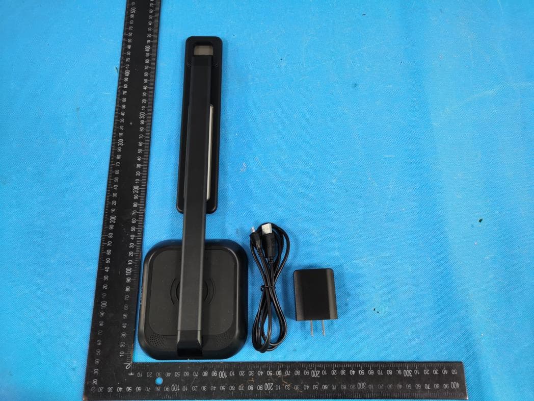
Click to zoom
Application Details
- Equipment Class
- DCD - Part 15 Low Power Transmitter Below 1705 kHz
- Date of Grant
- Nov 22, 2022
- Application Purpose
- Original Equipment
- Date of Application
- Nov 22, 2022
- Equipment Note
- LED Desk Lamp(with wireless charging function)
- Frequency Range
- 0.11100000 - 0.17500000
- Country
- China
Documents & Files
Document Text
Text extracted from the exhibit documents filed with the FCC. Open a document above to read the original.
Users Manual
⑧ 。 Unfold the lamp to standing and plug the power cord int。the base, then plug the USB or AC adapter into an outlet. 。 xl /王=二一 xl xl CAUTION: Do not use chemical solvents or harsh abrasives to clean as damage may occur. ⑧ WARNING: To reduce risk of fire, electric shock, or pers。nalinju时,donot install this lighting sγstem in a wet location. Patent and trademark information: vari.com/patents I ©2020 Varidesk, LLC All rights reserved. To turn on, tap the power icon. To adjust brightness, use the arrow icons. To adjust light color, tap on the light icon t。 toggle through 4 color options. α《〈@)》》 。 /\ 、/ { 号�导) • Natural White (4SOOK) •C。。lWhite (5600K) • Warm White (2800K) • So仕White(3400K) ..............................................· � CAUTION: Keep lamp away from materials that may burn. 。 To use the wireless charging function, place wireless charging compatible phone* 。nto the wireless charging pad on the lamp base. When the indicator light turns on, the phone is charging. When the ph。neis removed, the light will turn off. *Wireless charging compatible phone with built-in wireless charging receivers include, but aren ’ t limited to: • iPhone 8, 8 Plus, X, XS, XR, XS Max, 11, 11 Pro, 11 Pro Max • Samsung 56, 56 Edge, 57, 58, 58+, 59, 59+, Note 8, Note 9 • LG V40 Thinq, G7 Thinq, V35 Thinq •G。。gle Pixel 3, Pixel 3XL • Sony X23, XZ2, 23V •N。kla NS, N9, N。kia1520 & CAUTION: Do not stare directly int。 lamp light. This c。uldbe damaging to your eyes. (企 (800)207-2587 FCC WARNING This device complies with part 15 of the FCC Rules. Operation is subject to the following two conditions: (1) this device may not cause harmful interference, and (2) this device must accept any interference received, including interference that may cause undesired operation. Any changes or modifications not expressly approved by the party responsible for compliance could void the user's authority to operate the equipment. NOTE: This equipment has been tested and found to comply with the limits for a Class B digital device, pursuant to Part 15 of the FCC Rules. These limits are designed to provide reasonable protection against harmful interference in a residential installation. This equipment generates, uses and can radiate radio frequency energy and, if not installed and used in accordance with the instructions, may cause harmful interference to radio communications. However, there is no guarantee that interference will not occur in a particular installation. If this equipment does cause harmful interference to radio or television reception, which can be determined by turning the equipment off and on, the user is encouraged to try to correct the interference by one or more of the following measures: -- Reorient or relocate the receiving antenna. -- Increase the separation between the equipment and receiver. -- Connect the equipment into an outlet on a circuit different from that to which the receiver is connected. -- Consult the dealer or an experienced radio/TV technician for help. To maintain compliance with FCC’s RF Exposure guidelines, This equipment should be installed and operated with minimum distance between 20cm the radiator your body: Use only the supplied antenna.
Attestation Statements
Shenzhen Ruibeite Optoelectronics Co., Ltd. Family models difference declaration Product Name: LED Desk Lamp(with wireless charging function) Model Name: D102W-Z, D102W, 42686 Difference declaration: All the model are the same circuit and RF module, except the model name. Regards, Signature Name:David Ye Date: 2022-10-24
Cover Letter(s)
C5266091_X8_Ed.1 1/1 Letter of Authorization < Shenzhen Ruibeite Optoelectronics Co., Ltd. > Company: Shenzhen Ruibeite Optoelectronics Co., Ltd. Address: 3rd Floor, Building 1, Jinyuda Industrial Park, No. 159 Huangpu Road, Shajing Street, Baoan District, Shenzhen, China Product Name: LED Desk Lamp(with wireless charging function) Model Number: D102W-Z, D102W, 42686 FCC Identifier: 2A83D-42686 We authorize LGAI Technological Center S.A., Ronda de la Font del Carme, s/n, 08193 Bellaterra, Spain, to act on our behalf on all matters concerning the above named equipment. Any individual within LGAI Technological Center S.A. is authorized to act on our behalf and take action on the application. We declare that authorize LGAI Technological Center S.A., Ronda de la Font del Carme, s/n, 08193 Bellaterra, Spain, is allowed to forward all information related to the approval project to the Federal Communication Commission and to discuss any issues concerning the approval application. Any and all acts carried out by LGAI Technological Center S.A. on our behalf shall have the same effect as acts of our own. Name: David Ye Date: 10/24/2022 Title: Manager Signature of applicant:
Cover Letter(s)
C5266091_X10_Ed.2 1/1 < Shenzhen Ruibeite Optoelectronics Co., Ltd. > Office of Engineering Technology Federal Communications Commission 7435 Oakland Mills Road Columbia, MD 21046 Date: 2022-10-24 Subject: Request for Confidentiality FCC ID:2A83D-42686 To Whom It May Concern, Pursuant to the provisions of Sections 0.457 and 0.459 of Commission's rules (47CFR0.457, 0.459), we are requesting the Commission to withhold the following attachment(s) as confidential document from public disclosure. Exhibits Long-Term Confidentiality Short-Term Confidentiality NOTE 2 ID Label/Location No No Attestation Statement No No External Photos No Block Diagram ☐ Schematics ☐ Test Report No No Test Setup Photos No User’s Manual ☐ NOTE 1 Internal Photos ☐ NOTE 1 Parts List / Tune Up / BOM List ☐ RF Exposure Info No No Operational Description ☐ Cover Letter(s) No No SOFTWARE SECURITY REQUIREMENTS FOR U- NII DEVICES No NOTE 1: Long-Term Confidentiality may be permitted under special conditions (See II. LONG-TERM CONFIDENTIALITY, Section 3 of KDB 726920, use last in force) NOTE 2: Short-Term Confidentiality can be requested for a maximum of 180 days from the date of the grant. Above mentioned document contains detailed system and equipment description are considered as proprietary information in operation of the equipment. The public disclosure of above documents might be harmful to our company and would give competitor an unfair advantage in the market. In case of short-term Confidentiality, the applicant requests the exhibits selected above are withheld from public view for a period of _180_ days from the date of the Grant of Equipment Authorization and prior to marketing. C5266091_X10_Ed.2 1/1 It is our understanding that all measurement test reports, FCC ID label format and correspondent during certification review process cannot be granted as confidential documents and those information will be available for public review once the grant of equipment authorization is issued. Sincerely, Signature: Name:David Ye Title: Manager
External Photos
ATTACHMENT PHOTOGRAPHS OF EUT Photo 1 Photo 2 Photo 3 Photo 4 Photo 5 Photo 6 Photo 7 Photo 8 Photo 9 Photo 10 Photo 11
RF Exposure Info
FCC ID:2A83D-42686 1.Measuring Standard FCC Part 1(1.1310) and Part 2(2.1091), KDB 680106 D01v03r01 RF Exposure Wireless Charging App v03 1.2. Requiments Three different categories of transmitters are defined by the FCC in OET Bulletin 65. These categories are fixed installation, mobile, and portable and are defined as follows: o Fixed Installations: fixed location means that the device, including its antenna, is physically secured at a permanent location and is not able to be easily moved to another location. Additionally, distance to humans from the antenna is maintained to at least 2 meters. o Mobile Devices: a mobile device is defined as a transmitting device designed to be used in other than fixed locations and to be generally used in such a way that a separation distance of at least 20 centimeters is normally maintained between the transmitter's radiating structures and the body of the user or nearby persons. Transmitters designed to be used by consumers or workers that can be easily re-located, such as a wireless modem operating in a laptop computer, are considered mobile devices if they meet the 20 centimeter separation requirement. The FCC rules for evaluating mobile devices for RF compliance are found in 47 CFR §2.1091. o Portable Devices: a portable device is defined as a transmitting device designed to be used so that the radiating structure(s) of the device is/are within 20 centimeters of the body of the user. Portable device requirements are found in Section 2.1093 of the FCC's Rules (47 CFR§2.1093). The FCC also categorizes the use of the device as based upon the user’s awareness and ability to exercise control over his or her exposure. The two categories defined are Occupational/ Controlled Exposure and General Population/Uncontrolled Exposure. These two categories are defined as follows: Occupational/Controlled Exposure: In general, occupational/controlled exposure limits are applicable to situations in which persons are exposed as a consequence of their employment, who have been made fully aware of the potential for exposure and can exercise control over their exposure. This exposure category is also applicable when the exposure is of a transient nature due to incidental passage through a location where the exposure levels may be higher than the general population/uncontrolled limits, but the exposed person is fully aware of the potential for exposure and can exercise control over his or her exposure by leaving the area or by some other appropriate means. Awareness of the potential for RF exposure in a workplace or similar environment can be provided through specific training as part of a RF safety program. If appropriate, warning signs and labels can also be used to establish such awareness by providing prominent information on the risk of potential exposure and instructions on methods to minimize such exposure risks. General Population/Uncontrolled Exposure: The general population / uncontrolled exposure limits are applicable to situations in which the general public may be exposed or in which persons who are exposed as a consequence of their employment may not be made fully aware of the potential for exposure or cannot exercise control over their exposure. Members of the general public would come under this category when exposure is not employment-related; for example, in the case of a wireless transmitter that exposes persons in its vicinity. Warning labels placed on low-power consumer devices such as cellular telephones are not considered sufficient to allow the device to be considered under the occupational/controlled category, and the general population/uncontrolled exposure limits apply to these devices. 1.3 Test configuration 1, The field strength of both E-field was measured at 15cm, H-field was measured at 15cm surrounding the device, and 20 cm away from the surface from all coils using the equipment list above for determining compliance with the MPE requirements of FCC Part 1.1310. 2, The RF power density was measured at Under maximum load test 3, Maximum E-field measurements was made 15cm from each side of the EUT and H-field measurements was made 15cm from surrounding the EUT and 20 cm away from the surface from all coils. Along the side of the EUT and still 20cm away from the edge of the EUT, the field probes were positioned at the location where there is maximum field strength. The maximum E-field and H-field is reported below. 4, This device uses a wireless charging circuit for power transfer operating at the frequency of 111–175kHz. Thus, the 300kHz limits were used: E-field Limit = 614 (V/m); H-field limit = 1.63 (A/m). 1.4 Test Setup 2. Limits 3. MEASURING DEVICE AND TEST EQUIPMENT 2.1For MPE Measurement 4. Measuring Results EUT: LED Desk Lamp(with wireless charging function) Model Name. : D102W-Z Temperature: 24 °C Relative Humidity: 56% Pressure: 1010hPa Test Date: 2022-10-08 Test Voltage: DC 5V from Adapter half-load: Table 1. H-Field MPE Data-Top EUT Side E (A/m) Limits (A/m) Max load 0.799 1.63 Table 2. H-Field MPE Data- Surrounding EUT Side B(uT) A(uT) C (uT) D(above) (uT) Max load 0.98 1.014 0.994 0.978 EUT Side B(A/m) A(A/m) C (A/m) D(above) (A/m) Limits (A/m) Max load 0.784 0.811 0.795 0.782 1.63 Table 3. E-Field MPE E-Field Measurement (15cm) EUT Side B(V/m) A(V/m) E(V/m) C (V/m) D(above) (V/m) Limits (V/m) Max load 4.469 4.458 4.497 3.896 3.995 614 empty load: Table 1. H-Field MPE Data-Top EUT Side E(A/m) Limits (A/m) Max load 0.797 1.63 Table 2. H-Field MPE Data- Surrounding EUT Side B(uT) A(uT) C (uT) D(above) (uT) Max load 0.946 0.994 0.985 0.945 EUT Side B(A/m) A(A/m) C (A/m) D(above) (A/m) Limits (A/m) Max load 0.757 0.795 0.788 0.756 1.63 Table 3. E-Field MPE E-Field Measurement (15cm) EUT Side B(V/m) A(V/m) E(V/m) C (V/m) D(above) (V/m) Limits (V/m) Max load 3.810 4.478 4.476 3.804 3.995 614 Fully loaded: Table 1. H-Field MPE Data-Top EUT Side E(A/m) Limits (A/m) Max load 0.810 1.63 Table 2. H-Field MPE Data- Surrounding EUT Side B(…
Text truncated - open the document above for the full version.
Test Report
D102W-ZQuick Charge Desk Lamp PCBA Specification Model:D102W-Z Version:V2 date:2019-08-31 1. product description Using the principle of electromagnetic induction can be used for Samsung's S6Edge\S7\S7Edge\Note5\Note8\S8\S8+\S9\Note9\S10\S20\Note10 Perform fast wireless charging with iPhone8\iphoneX\iPhone11\iPhone12\iPhone13 series, and have good compatibility with 5W wireless charging mobile phones, and can support Qi standard receivers such as Ti, IDT, PANASONIC, etc. 2. Specifications 2.1 maximum rating parameter symbol rated value unit Working temperature Ta -40~+85 °C stored temperature Tstg -65~+150 °C storage humidity Tstr <95% RH supply voltage Vcc -0.5~+6.5 V supply current Imax 2 A 2.2 Rated parameter Test conditions: ambient temperature 25°C. Test Conditions rated value minimum value maxim um value unit normal mode power consumpti on Vcc=5V 100 80 150 mW working frequency Adjust load and distance / 105 189 KHz transmis sion efficienc y bq51013xEVM test 70 50 76 % Operatin g Voltage 5W output 5 4.5 5.5 V Operatin g Voltage 10W output 9 8.5 10 V Output Power fast mode 9.5 9 10 W working distance bq51013xEVM test 5 2 8 mm 2.3:Other parameters PCB board size 72.5*30*1.0 mm Coil + magnet size 73*49.5*2.3 mm Qi A11 single coil 3. LED status indication • After the power is turned on, the LEDs display in sequence: blue, red color\sta tus power on standby charging full wrong blue off always on off off red always on off always on flash Error description: There are two situations for errors: one is power-on error: this is an error in the module's own inspection, which may be due to excessive power supply voltage, abnormal temperature check, or coil error. The other is a working process error: mainly to detect foreign objects or excessive temperature. 4. Dimensions 5:lamp part 5.1:Product features: Beautiful and stylish • The light source adopts secondary optical technology • The light is soft and uniform without dark spots and ghosting • Advanced constant current technology, no flicker, protecting eyesight • Built-in Qi standard wireless charger • 4 color temperatures, stepless Dimming • Height can be adjusted freely within 40 cm range • Lamp head can be up and down 120 degrees The thickness is not measured at the back bend Handle 12.5 2.0 8 1 21.5 0.5 41.5 0.5 0 43.5 -0.5 High temperature tape Ferrite technical requirements: 1. Use manganese zinc BP40 2. The parts are smooth and clean, and no convex dents shall appear 3. Products must be environmentally friendly Coil technical requirements: 1. Wire specification: 0.08mm*45P enameled copper wire 2.Coil specifications:COIL, ID21.5*21.5*0.08*45P*1P*x10TS*0.55(max) 3. Cable length 5±1mm; Lead immersion length 2+1/- 0.5mm. 4. Neat winding, do not damage the surface enamel layer; Appearance requirements: Class 2. 5. Unnoted size according to the drawing file. 6. Unmarked tolerance: wire 0.2mm, R angle 0.5mm. 7. The product meets the requirements of halogen- free and meets the salt spray test 48H. 8. Do not replace materials and surface treatment without permission. 9. The symbol ball on the drawing is the key control dimensioning Size 10.7 CPK>0.7 Finished electrical specifications: (@1V 100KHZ) Finished product (coil + ferrite) LS: 7.0uH±5% DCR:100m Ω(max) Q : ﹥TBD 5 1 2+1/ - 0.5 18 0.5 ferite large:0.8 0.1 ferite small:0.5 0.1 coil+tab:0.55 0.1 Adhesive backing:0.05 3M 9488A:0.15 Total:1.65max SIZE TEST ITEM Parameter Conditions SAMPLE Equipment Judge NO.1 NO.2 NO.3 NO.4 NO.5 Thickness 1.65mm MAX ___ 1.57 1.59 1.56 1.56 1.57 Callipers OK Lead wire length S=F=5± 1.0mm ___ 5.06 4.80 4.58 4.57 4.65 2.5D OK Solder length 2+1-0.5mm ___ 1.75 1.58 1.68 1.87 1.84 2.5D OK O.D. 41.5± 0.5mm ___ 41.13 41.22 41.24 41.25 41.26 2.5D OK I.D. 21.5± 0.5mm ___ 21.33 21.35 21.52 21.73 21.55 2.5D OK Outer diameter of magnetic disc 43.5± 0.5mm ___ 43.20 43.26 43.23 43.30 43.21 2.5D OK spacing 12.5+/-2 ___ 11.33 12.53 12.21 11.19 10.58 2.5D OK
Test Report
Report No.: S22091401202001 Version.1.1Page 1 of 24 FCC Test Report FCC ID:2A83D-42686 Product: LED Desk Lamp(with wireless charging function) Trade Name: N/A Model Number: D102W-Z Family Model: D102W, 42686 Report No.: S22091401202001 Prepared for Shenzhen Ruibeite Optoelectronics Co., Ltd. 3rd Floor, Building 1, Jinyuda Industrial Park, No. 159 Huangpu Road, Shajing Street, Baoan District, Shenzhen, China Prepared by Shenzhen NTEK Testing Technology Co., Ltd. 1/F, Building E, Fenda Science Park, SanweiCommunity,Xixiang Street, Bao’an District, Shenzhen P.R. China Tel:400-800-6106,0755-2320 0050 / 2320 0090 Website:http://www.ntek.org.cn Report No.: S22091401202001 Version.1.1Page 2 of 24 TEST RESULTCERTIFICATION Applicant’s name ................. : Shenzhen Ruibeite Optoelectronics Co., Ltd. Address ................................. : 3rd Floor, Building 1, Jinyuda Industrial Park, No. 159 Huangpu Road, Shajing Street, Baoan District, Shenzhen, China Manufacturer's Name .......... : Shenzhen Ruibeite Optoelectronics Co., Ltd. Address ................................. : 3rd Floor, Building 1, Jinyuda Industrial Park, No. 159 Huangpu Road, Shajing Street, Baoan District, Shenzhen, China Model and/or type reference : D102W-Z Family Model: D102W, 42686 Test sample number S220914012002 Standards ............................. : FCC part 15C ANSI C63.10:2013 KDB 680106 D01 RF Exposure Wireless Charging App v03r01 This device described above has been tested by ShenzhenNTEK Testing Technology Co., Ltd., and the test results show that the equipment under test (EUT) is in compliance with the FCC requirements. And it is applicable only to the tested sample identified in the report. This report shall not be reproduced except in full, without the written approval of ShenzhenNTEK Testing Technology Co., Ltd., this document may be altered or revised by Shenzhen NTEK Testing Technology Co., Ltd., personnel only, and shall be noted in the revision of the document. The test results of this report relate only to the tested sample identified in this report. Date of Test ............................................ : Date (s) of performance of tests ............. : 16 Sep. 2022 ~ 13 Oct. 2022 Date of Issue ........................................... : 14 Oct. 2022 Test Result ............................................... : Pass Testing Engineer : (Allen Liu) Authorized Signatory : (Alex Li) Report No.: S22091401202001 Version.1.1Page 3 of 24 Table of Contents Page 1 . TEST SUMMARY 4 1.1 FACILITIES AND ACCREDITATIONS 5 1.2 LABORATORY ACCREDITATIONS AND LISTINGS 5 1.3 MEASUREMENT UNCERTAINTY 5 2 . GENERAL INFORMATION 7 2.1 GENERAL DESCRIPTION OF EUT 7 2.2 DESCRIPTION OF TEST SETUP 9 2.3 DESCRIPTION TEST PERIPHERAL AND EUT PERIPHERAL 10 2.4 MEASUREMENT INSTRUMENTS LIST 11 3 . EMC EMISSION TEST 12 3.1 CONDUCTED EMISSION MEASUREMENT 12 3.1.1 POWER LINE CONDUCTED EMISSION 12 3.1.2 TEST PROCEDURE 13 3.1.3 TEST SETUP 13 3.1.4 EUT OPERATING CONDITIONS 13 3.1.5 TEST RESULTS 14 3.2 RADIATED EMISSION MEASUREMENT 16 3.2.1 LIMITS OF RADIATED EMISSION MEASUREMENT 16 3.2.2 TEST PROCEDURE 17 3.2.3 TEST SETUP 18 3.2.4 TEST RESULTS 19 4. BANDWIDTH TEST 22 4.1TEST PROCEDURE 22 4.2TEST SETUP 22 4.3 TEST RESULT 23 5. ANTENNA APPLICATION 24 5.1 Antenna Requirement 24 5.2 Result 24 Report No.: S22091401202001 Version.1.1Page 4 of 24 1. TEST SUMMARY Test procedures according to the technical standards: EMC Emission Standard Test Item FCC Rules Limit Judgment Remark FCC part 15C ANSI C63.10:2013 Conducted Emission §15.207 Class B PASS Radiated Emission §15.209 Class B PASS ANTENNA APPLICATION §15.203 / PASS 20dB BANDWIDTH §15.215 Class B PASS NOTE: (1)’N/A’ denotes test is not applicable in this Test Report (2) For client’s request and manual description, the test will not be executed. Report No.: S22091401202001 Version.1.1Page 5 of 24 1.1 FACILITIES AND ACCREDITATIONS All measurement facilities used to collect the measurement data are located at 1/F, Building E, Fenda Science Park, Sanwei Community, Xixiang Street, Bao’an District, Shenzhen 518126 P.R. China. The sites are constructed in conformance with the requirements of ANSI C63.7, ANSI C63.10 and CISPR Publication 22. 1.2 LABORATORY ACCREDITATIONS AND LISTINGS Site Description CNAS-Lab. : The Certificate Registration Number is L5516. IC-Registration : The Certificate Registration Number is 9270A-1. FCC- Accredited : Test Firm Registration Number:463705. Designation Number: CN1184 A2LA-Lab. : The Certificate Registration Number is 4298.01 This laboratory is accredited in accordance with the recognized International Standard ISO/IEC 17025:2005General requirements for the competence of testing and calibration laboratories. This accreditation demonstratestechnical competence for a defined scope and the operation of a laboratory quality management system (refer to joint ISO-ILAC-IAF Communiqué dated 8 January 2009). Name of Firm : Shenzhen NTEK Testing Technology Co., Ltd. Site Location : 1/F, Building E, Fenda Science Park, Sanwei Community, Xixiang Street, Bao’an District, Shenzhen 518126 P.R. China. 1.3 MEASUREMENT UNCERTAINTY The reported uncertainty of measurement y ±U, where expended uncertainty U is based on a standard uncertainty multiplied by a coverage factor of k=2, providing a level of confidence of approximately 95 %. No. Item Uncertainty 1 Conducted Emission Test ±2.80dB 2 All emissions, radiated(9KHz~30MHz) ±6dB 3 All emissions, radiated(30MHz~1GHz) ±2.64dB All emissions, radiated(>1GHz) ±2.40dB 4 BANDWIDTH ±0.39% Report No.: S22091401202001 Version.1.1Page 6 of 24 Revision History Report No. Version Description Issued Date S22091401202001 Rev.01 Initial issue of report 14 Oct. 2022 Report No.: S22091401202001 Version.1.1Page 7 of 24 2. GENERAL INFORMATION 2.1GENERAL DESCRIPTION OF EUT Product Feature and Specification Equipment LED Desk Lamp(with wireless charging function) Trade Name N/A FCC ID 2A83D-42686 Model No. D102W-Z Family Model D102W, 42686 Model Differ…
Text truncated - open the document above for the full version.
Test Setup Photos
Radiated Measurement Photos Conducted Measurement Photos
Contact Information
Applicant
David Ye
Technical Contact
Non-Technical Contact
Shenzhen NTEK Testing Technology Co., Ltd.Alex Li
[email protected]86-755-6115 6588
Test Firm
Shenzhen NTEK Testing Technology Co., Ltd.Alex Li
[email protected]+86-755-6115-9384
Technical Specifications
| # | Rule Parts | Frequency Range | Power Output |
|---|---|---|---|
| 1 | 15C | 0.111 MHz - 0.175 MHz | - |