FCCID.CO- FCC ID Database
HomeCompaniesEquipment ClassesSearch

© 2026 FCC ID Database. All rights reserved.

AboutContactData sourced from FCC public records
  1. Home/
  2. AVC TECHNOLOGY (INTERNATIONAL) LTD/
  3. 2A84F-SL30

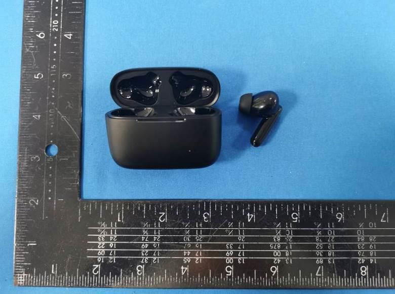
2A84F-SL30S-LIVE30 - Premium Low Latency True Wireless Earbuds with Call Enhancement
AVC TECHNOLOGY (INTERNATIONAL) LTD
S-LIVE30 - Premium Low Latency True Wireless Earbuds with Call Enhancement - FCC ID 2A84F-SL30 - AVC TECHNOLOGY (INTERNATIONAL) LTD
Click to zoom

Application Details

Equipment Class
DSS - Part 15 Spread Spectrum Transmitter
Date of Grant
Nov 06, 2022
Application Purpose
Original Equipment
Date of Application
Nov 06, 2022
Equipment Note
S-LIVE30 - Premium Low Latency True Wireless Earbuds with Call Enhancement
Frequency Range
2402.00000000 - 2480.00000000
Company
AVC TECHNOLOGY (INTERNATIONAL) LTD
Country
China

Documents & Files

Select a file to view
Users Manual

↗

Cover Letter(s)

↗
↗
↗

External Photos

↗

ID Label/Location Info

↗

Internal Photos

↗

RF Exposure Info

↗

Test Report

↗
↗
↗

Test Setup Photos

↗

Document Text

Text extracted from the exhibit documents filed with the FCC. Open a document above to read the original.

Users Manual

ItemCodeFunction 2.1Power on 2.2Power off 1.22.3Pairing 1.32.4Left Channel 1.42.5Right Channel 1.52.6 Main earbud is paired with mobile phone 1.62.7 Main earbud is disconnected with mobile phone 1.72.8Incoming call 1.82.9Call end 1.92.10Reject call 1.102.11Entertainment Mode 1.112.12Low Battery 1.122.13Maximum volume 1.132.14Minimum volume 1.142.17Earbud fixed ringtone CodeStatusVoice&PromptIndicator Light 3.1Power offPower OnBlue light on for 1 second 3.2chargingPower OnBlue light on for 1 second charging According to the status, the corresponding prompt According to the status, the corresponding prompt in shutdown statusPairing Mode Blue and white lights flash alternately slowly 3.5 in powered-on status After a short beep, activate the voice assistant sound No light 3.6 in powered-on status After a short beep, turn off the voice assistant sound No light 3.7Connection StatusEntertainment ModeNo light 3.8Connection StatusNormal ModeNo light 3.9 When the call is not connected /No light 3.10in calling statuscall endNo light 3.11 When the call is not connected and the three-way call call rejectedNo light 3.12dialing Cancel dial: beep Apple mobile phone no sound No light 3.13Talking/No light 3.14Three-way calling/No light 3.15Three-way calling/No light Bluetooth Name:SOUL S-LIVE30 1.Indicator light 2.Voice prompt (English voice) OpterationFlash wayVoice Power On Power Off (TWS is connected, the master earbud is connected to the mobile phone) No LightPairing Mode TWS Pairing The blue and white lights of the main and auxiliary earbud flash alternately quickly Left Channel earbuds and mobile phone pairing status The blue and white lights of the main earbud flash alternately slowly, and the auxiliary earbud has no lights Right Channel Pairing time (mobile phone) If there is no connection within 5 minutes, the earbud will automatically shut down Pairing successful When making an call (not answered)No lightDisconnected Incoming callNo lightMobile phone ringtone TalkingNo lightCall Ended Listening musicNo lightCall rejected Power off white light of main and auxiliary earbud will be on for 1 second Entertainment Mode Charging white light of main and auxiliary earbud is always on Low Battery full chargeWhite light will be off"beep" RESET white and blue light of earbud will flashes once "beep" Alarm when battery is lower than 3.5 V (Note: After the low power reminder, you can still listen to music for 15 minutes) Beep once every 2 minutes SOUL RingTone 3.Function operation instructions FunctionOperation Manual pairing and power on For the main and auxiliary earbud, press and hold the power button for 3 seconds, the two earphones will automatically enter the TWS search pairing mode (the blue and white lights flash alternately), and then automatically complete the TWS connection; the main earphone will automatically enter the mobile phone pairing mode (alternate blue and white lights). there is no light on the auxiliary earbud. If the primary and secondary devices fail to reconnect in time (more than 10 seconds), user need to click the power button to make the earbud into TWS reconnection mode. (Note: If the primary or auxiliary earbud has never been connected in TWS mode, and the auxiliary earbud has been connected to the second mobile phone alone, user need to clear the pairing record before connect it to the primary earbud normally.) Automatic power-on pairing Open the charging case and take out the earbuds, the two earbuds will automatically enter the TWS search pairing mode (the blue and white lights flash alternately quickly), and then automatically complete the pairing of the earbuds; the primary earbud will automatically enter the mobile phone pairing mode (the blue and white lights flash alternately slowly), the secondary earbud with No lights. If the primary and secondary earbuds fail to reconnect in time (more than 10 seconds), user need to click the power button to make the earbud into TWS reconnection mode. (Note: If the parimary or auxiliary earbud has never been connected in TWS mode, and the auxiliary earbud has been connected to the second mobile phone alone, user need to clear the pairing record before connect it to the primary earbud normally.) Take out any earphone separately from the charging case. If the other earphone is not taken out within 30S, the first earphone will automatically connect back to the mobile phone. If there is no connection record, it will automatically enter the pairing mode. For the primary or secondary earbud, press and hold the power button for 5 seconds to enter pairing mode. If the other earphone is not taken out within 30S, the first earphone will automatically connect back to the mobile phone, if there is no connection record, it will automatically enter the pairing mode Turn on IOS voice assistant(SIRI & Google Assistance Quickly press the left earphone power button three times (after Siri is activated, user can only speak one sentence, then user have to manually click the phone voice, otherwise siri will be automatically turned off) Turn off IOS voice assistant(SIRI & Google Assistance Press the left earphone power button (Apple system only) Turn on entertainment mode (low latency)Press and hold the power button of the left earphone for 1S, and release it when you hear the voice prompt "Entertainment Mode" Turn off entertainment mode (low latency)Press and hold the power button of the left earphone for 1S. When you hear the voice prompt "Normal Mode", release it and start it Answer callPress the right earphone power button once hang upPress the left earphone power button once Reject callDouble-click the right earphone power button cancel dialClick the MFB button of the right earphone to cancel the dialing before the other party answering the call Device switching During a call, long press the MFB button of the right earphone for 2S to switch the call voice between the earphone and the mobile phone Three-way call 1, hang up the current call to answer a …

Text truncated - open the document above for the full version.

Cover Letter(s)

Sincerely, Name/Title: Ken Chung/Manager Company: AVC TECHNOLOGY (INTERNATIONAL) LTD Address: 6th Floor, Enterprise Square Three, 39 Wang Chiu Road, Kowloon Bay, Hong Kong China Phone: +852-93426333 Fax: +852-27643108 E-Mail: [email protected]

External Photos

FCC ID: 2A84F-SL30 External Photos of the EUT Photo 1 Photo 2 Photo 3 FCC ID: 2A84F-SL30 Photo 4 Photo 5 Photo 6 FCC ID: 2A84F-SL30 Photo 7 Left side Photo 8 Photo 9 FCC ID: 2A84F-SL30 Photo 10 Photo 11 Photo 12 FCC ID: 2A84F-SL30 Photo 13 Photo 14 Right side Photo 15 FCC ID: 2A84F-SL30 Photo 16 Photo 17 Photo 18 FCC ID: 2A84F-SL30 Photo 19 Photo 20 Photo 21

ID Label/Location Info

Label and Location Size: L: 1.0cm*W: 0.5cm Label and Location FCC ID : 2A84F-SL30

Internal Photos

FCC ID: 2A84F-SL30 Internal Photos of the EUT Left side Photo 1 Photo 2 Photo 3 FCC ID: 2A84F-SL30 Photo 4 Photo 5 Photo 6 BT (Ceramic) Antenna FCC ID: 2A84F-SL30 Photo 7 Right side Photo 8 Photo 9 FCC ID: 2A84F-SL30 Photo 10 Photo 11 Photo 12 BT (Ceramic) Antenna FCC ID: 2A84F-SL30 Photo 13 Photo 14

RF Exposure Info

RF Exposure evaluation FCC ID: 2A84F-SL30 1.1. Applicable Standard According to §1.1307(b)(1), systems operating under the provisions of this section shall be operated in a manner that ensures that the public is not exposed to radio frequency energy level in excess of the Commission’s guidelines. According to §1.1310 and §2.1093 RF exposure requirement KDB447498 v06: Mobile and Portable Devices RF Exposure Procedures and Equipment Authorization Policies 1.2. Requirement According to KDB447498 D01 General RF Exposure Guidance v06 Section 4.3.1 Standalone SAR test exclusion considerations: “Unless specifically required by the published RF exposure KDB procedures, standalone 1-g head or body and 10-g extremity SAR evaluation for general population exposure conditions, by measurement or numerical simulation, is not required when the corresponding SAR Test Exclusion Threshold condition, listed below, is satisfied. These test exclusion conditions are based on source-based time-averaged maximum conducted output power of the RF channel requiring evaluation, adjusted for tune-up tolerance, and the minimum test separation distance required for the exposure conditions.22 The minimum test separation distance is determined by the smallest distance from the antenna and radiating structures or outer surface of the device, according to the host form factor, exposure conditions and platform requirements, to any part of the body or extremity of a user or bystander (see 5) of section 4.1). To qualify for SAR test exclusion, the test separation distances applied must be fully explained and justified by the operating configurations and exposure conditions of the transmitter and applicable host platform requirements, typically in the SAR measurement or SAR analysis report, according to the required published RF exposure KDB procedures. When no other RF exposure testing or reporting is required, a statement of justification and compliance must be included in the equipment approval, in lieu of the SAR report, to qualify for the SAR test exclusion. When required, the device specific conditions described in the other published RF exposure KDB procedures must be satisfied before applying these SAR test exclusion provisions; for example, handheld PTT two-way radios, handsets, laptops & tablets etc.23 “ [(max. power of channel, including tune-up tolerance, mW)/ (min. test separation distance, mm)] · [√f (GHz)] ≤ 3.0 for 1-g SAR and ≤ 7.5 for 10-g extremity SAR, where: • f (GHz) is the RF channel transmit frequency in GHz • Power and distance are rounded to the nearest mW and mm before calculation • The result is rounded to one decimal place for comparison • 3.0 and 7.5 are referred to as the numeric thresholds in the step 2 below The test exclusions are applicable only when the minimum test separation distance is ≤ 50 mm and for transmission frequencies between 100 MHz and 6 GHz. When the minimum test separation distance is < 5 mm, a distance of 5 mm according to 5) in section 4.1 is applied to determine SAR test exclusion. 1.3. Manufacturing tolerance GFSK (Peak) Channel Channel 0 Channel 39 Channel 78 Target (dBm) 0.0 0.0 0.0 Tolerance ±(dB) 1.0 1.0 1.0 π/4DQPSK (Peak) Channel Channel 0 Channel 39 Channel 78 Target (dBm) 0.0 0.0 0.0 Tolerance ±(dB) 1.0 1.0 1.0 Page 2 of 2 2. E v a l u a t i o n R e s u l t Evaluation Results Band/Mode f (GHz) Antenna Distance (mm) RF output power (including tune-up tolerance) SAR Test Exclusion Threshold SAR Test Exclusion dBm mW BT 2.450 5 1.0 1.2589 0.3941<3.0 Yes 3. C o n c l u s i o n The measurement results comply with the FCC Limit per 47 CFR 2.1093 for the uncontrolled RF Exposure and SAR Exclusion Threshold per KDB 447498 v06 .....................End of Report.........................

Test Report

2.4GHz2012ChipAntenna:RANT2012F245C02 Dimension(mm) L2.05+-0.15 W1.20+-0.15 T0.45+-0.10 No.TerminalName 1Feeding/GNG 2GND Application: WLAN,802.11b/g,Bluetooth,WLAN,etc... Features SMD,highreliability,ultraImpact,Omni-directional... PartnumberInformation RANT2012F245C02 (A)(B)(C)(D)(E)(F) (A)ProductTypeChipAntenna (B)SizeCode2.0x1.2mm(+-0.2mm) (C)MaterialHighKmaterial (D)Frequency2.4~2.5GHz (E)FeedingmodePIFA&SingleFeeding (F)AntennatypeType=02 ElectricalSpecification WorkingFrequencyRange2400~2484MHz Bandwidth84(Min.) PeakGain1.95 dBi (Typ.) Impedance50Ohm Returnloss10dB(Min) PolarizationLinear AzimuthBeamwidthOmni-directional OperationTemperature( °C )-40~85 °C ResistancetoSolderingHeats 10sec.(@280°C) TerminationNi/Au(Leadless) ThespecificationisdefinedonEVB. DimensionandTerminalConfiguration 咏成國際科技有限公司電話:13530576606 RAINInternationalTechnologyCo.,Ltd.TEL:13530576606 2.4GHz2012ChipAntenna:RANT2012F245C02 EvaluationBoardReference PCBDimensionAntennaLayoutReference Unit:mm ElectricalCharacteristics ReturnLoss ReturnLoss&Radiation 1 Frequency(MHz) S11(dB) 2400-10.77 2450-24.81 2484-10.243 Radiation Z Y X 2400MHz2450MHz2500MHz Efficiency70.56%75.25%71.01% PeakGain1.72dBi1.95dBi1.69dBi Directivity2.26dBi2.69dBi2.11dBi 2.4GHz2012ChipAntenna:RANT2012F245C02 TapingSpecifications ReelandTapingSpecification ReelSpecification TYPESIZEABCD 20127”5K/Reel 9.0±0.5 60±213.5±0.5178±2 TappingSpecification PackagingTypeABWEFGHTDP PaperType2012 1.50±0.202.30±0.208.0±0.201.75±0.103.5±0.054.0±0.102.0±0.050.75±0.101.57±0.104.0±0.1 2.4GHz2012ChipAntenna:RANT2012F245C02 ReliabilityTable TestItemProcedure Requirements CeramicType Remark (Reference) Electrical Characterization Fulfilltheelectrical specification UserSpec. Thermal Shock 1.Preconditioning: 50±10°C/1hr,thenkeepfor24±1hrsatroomtemp. 2.Initialmeasure:Spec:referInitialspec. 3.Rapidchangeoftemperaturetest: -30°Cto+85°C;100cycles; 15minutesatLowercategorytemperature; 15minutesatUppercategorytemperature. NoVisibleDamage. Fulfilltheelectrical specification. MIL-STD-202 107 Temperature Cycling 1.Initialmeasure:Spec:referInitialspec. 2.100Cycles(-30°Cto+85°C),SoakMode=1(2Cycle/hours). 3.Measurementat24±2Hoursaftertestcondition. NoVisibleDamage. Fulfilltheelectrical specification. JESD22 JA104 HighTemperature Exposure 1.Initialmeasure:Spec:referInitialspec. 2.Unpowered;500hours@T=+85°C. 3.Measurementat24±2hoursaftertest. NoVisibleDamage. Fulfilltheelectrical specification. MIL-STD-202 108 LowTemperature Storage 1.Initialmeasure:Spec:referInitialspec. 2.Unpowered:500hours@T=-30°C. 3.Measurementat24±2hoursaftertest. NoVisibleDamage. Fulfilltheelectrical specification. MIL-STD-202 108 Solderability (SMDBottomSide) Dippingmethod: a.Temperature:235±5°C b.Dippingtime:3±0.5s Thesoldershouldcover over95%ofthecritical areaofbottomside. IEC60384-21/22 4.10 SolderingHeat Resistance (RSH) Preheatingtemperature:150±10°C. Preheatingtime:1~2min. Soldertemperature:260±5°C. Dippingtime:5±0.5s NoVisibleDamage.IEC60384-21/22 4.10 Vibration5g'sfor20min.,12cycleseachof3orientations Note:Use8"X5"PCB.031"thick7securepointson,onelong sideand2securepointsatcornersofoppositesides.Parts mountedwithin2"fromanysecurepoint.Testfrom10-2000 Hz. NoVisibleDamage.MIL-STD-202 Method204 Mechanical Shock Threeshocksineachdirectionshallbeappliedalongthethree mutuallyperpendicularaxesofthetestspecimen(18shocks) Peakvalue:1,500g’s Duration:0.5ms Velocitychange:15.4ft/s Waveform:Half-sine NoVisibleDamage.MIL-STD-202 Method213 Humidity Bias 1.Humidity:85%R.H.,Temperature:85±2°C. 2.Time:500±24hours. 3.Measurementat24±2hrsaftertestcondition. NoVisibleDamage. Fulfilltheelectrical specification. MIL-STD-202 Method106 2.4GHz2012ChipAntenna:RANT2012F245C02 _ Board Flex (SMD) 1.Mountingmethod: IR-Reflow.PCBSize(L:100×W:40×T:1.6mm) 2.Applytheloadindirectionofthearrowuntilbendingreaches 2mm. NoVisibleDamage.AEC-Q200 005 AdhesionForceof1.8Kgfor60seconds.NoVisibleDamage Magnificationof20Xor greatermaybeemployed forinspectionofthe mechanicalintegrityofthe devicebodyterminalsand body/terminaljunction. AEC-Q200 006 Physical Dimension Anyapplicablemethodusingx10magnification,micrometers, calipers,gauges,contourprojectors,orothermeasuring equipment,capableofdeterminingtheactualspecimen dimensions. Inaccordancewith specification. JESD22 JB100 RevisionHistory RevisionDateContent 12020/10/15NewDatasheet

Test Report

Shenzhen CTA Testing Technology Co., Ltd. Room 106, Building 1, Yibaolai Industrial Park, Qiaotou Community, Fuhai Street, Bao’an District, Shenzhen, China Shenzhen CTA Testing Technology Co., Ltd. Room 106, Building 1, Yibaolai Industrial Park, Qiaotou Community, Fuhai Street, Bao’an District, Shenzhen, China Tel:+86-755 2322 5875 E-mail:[email protected] Web:http://www.cta-test.cn FCC PART 15 SUBPART C TEST REPORT FCC PART 15.247 Report Reference No. ..................... : FCC ID. ............................................ : CTA22092100101 2A84F-SL30 Compiled by ( position+printed name+signature) .. : File administrators Zoey Cao Supervised by ( position+printed name+signature) .. : Project Engineer Amy Wen Approved by ( position+printed name+signature) .. : RF Manager Eric Wang Date of issue ..................................... : Oct. 08, 2022 Testing Laboratory Name .............. : Shenzhen CTA Testing Technology Co., Ltd. Address ............................................ : Room 106, Building 1, Yibaolai Industrial Park, Qiaotou Community, Fuhai Street, Bao‘an District, Shenzhen, China Applicant’s name ............................ : AVC TECHNOLOGY (INTERNATIONAL) LTD Address ............................................ : 6th Floor, Enterprise Square Three, 39 Wang Chiu Road, Kowloon Bay,Hong Kong Test specification ...........................: Standard ........................................... : FCC Part 15.247 Shenzhen CTA Testing Technology Co., Ltd. All rights reserved. This publication may be reproduced in whole or in part for non-commercial purposes as long as the Shenzhen CTA Testing Technology Co., Ltd. is acknowledged as copyright owner and source of the material. Shenzhen CTA Testing Technology Co., Ltd. takes no responsibility for and will not assume liability for damages resulting from the reader's interpretation of the reproduced material due to its placement and context. Test item description .....................: S-LIVE30 - Premium Low Latency True Wireless Earbuds with Call Enhancement Trade Mark ....................................... : SOUL Manufacturer .................................... : AVC TECHNOLOGY (INTERNATIONAL) LTD Model/Type reference....................... : S-LIVE30 Listed Models .................................. : SL30, SLE30 Modulation ....................................... : GFSK, Π/4DQPSK Frequency .......................................... From 2402MHz to 2480MHz Rating ............................................... : DC 3.7V From Battery and DC 5.0V From external circuit Result................................................ : PASS Report No.: CTA22092100101 Page 2 of 50 Shenzhen CTA Testing Technology Co., Ltd. Room 106, Building 1, Yibaolai Industrial Park, Qiaotou Community, Fuhai Street, Bao’an District, Shenzhen, China Tel:+86-755 2322 5875 E-mail:[email protected] Web:http://www.cta-test.cn T E S T R E P O R T Equipment under Test : S-LIVE30 - Premium Low Latency True Wireless Earbuds with Call Enhancement Model /Type : S-LIVE30 Listed Models : SL30, SLE30 Applicant : AVC TECHNOLOGY (INTERNATIONAL) LTD Address : 6th Floor, Enterprise Square Three, 39 Wang Chiu Road, Kowloon Bay,Hong Kong Manufacturer : AVC TECHNOLOGY (INTERNATIONAL) LTD Address : 6th Floor, Enterprise Square Three, 39 Wang Chiu Road, Kowloon Bay,Hong Kong Test Result: PASS The test report merely corresponds to the test sample. It is not permitted to copy extracts of these test result without the written permission of the test laboratory. Report No.: CTA22092100101 Page 3 of 50 Shenzhen CTA Testing Technology Co., Ltd. Room 106, Building 1, Yibaolai Industrial Park, Qiaotou Community, Fuhai Street, Bao’an District, Shenzhen, China Tel:+86-755 2322 5875 E-mail:[email protected] Web:http://www.cta-test.cn Contents 1 T E S T S T A N D A R D S ................................................................. 4 2 S U M M A RY ............................................................................ 5 2.1 General Remarks 5 2.2 Product Description 5 2.3 Equipment Under Test 5 2.4 Short description of the Equipment under Test (EUT) 5 2.5 EUT operation mode 6 2.6 Block Diagram of Test Setup 6 2.7 Related Submittal(s) / Grant (s) 6 2.8 Modifications 6 3 T E S T E N V I R O N M E N T .............................................................. 7 3.1 Address of the test laboratory 7 3.2 Test Facility 7 3.3 Environmental conditions 7 3.4 Summary of measurement results 8 3.5 Statement of the measurement uncertainty 8 3.6 Equipments Used during the Test 9 4 T E S T C O N D I T I O N S A N D R E S U L T S ........................................... 10 4.1 AC Power Conducted Emission 10 4.2 Radiated Emission 13 4.3 Maximum Peak Output Power 19 4.4 20dB Bandwidth 20 4.5 Frequency Separation 23 4.6 Number of hopping frequency 25 4.7 Time of Occupancy (Dwell Time) 27 4.8 Out-of-band Emissions 30 4.9 Pseudorandom Frequency Hopping Sequence 36 4.10 Antenna Requirement 37 5 T E S T S E T U P P H O T O S O F T H E E U T ......................................... 38 6 P H O T O S O F T H E E U T ........................................................... 39 Report No.: CTA22092100101 Page 4 of 50 Shenzhen CTA Testing Technology Co., Ltd. Room 106, Building 1, Yibaolai Industrial Park, Qiaotou Community, Fuhai Street, Bao’an District, Shenzhen, China Tel:+86-755 2322 5875 E-mail:[email protected] Web:http://www.cta-test.cn 1 T E S T S T A N D A R D S The tests were performed according to following standards: FCC Rules Part 15.247: Frequency Hopping, Direct Spread Spectrum and Hybrid Systems that are in operation within the bands of 902-928 MHz, 2400-2483.5 MHz, and 5725-5850 MHz. ANSI C63.10-2013: American National Standard for Testing Unlicensed Wireless Devices Report No.: CTA22092100101 Page 5 of 50 Shenzhen CTA Testing Technology Co., Ltd. Room 106, Building 1, Yibaolai Industrial Park, Qiaotou Community, Fuhai Street, Bao’an District, Shenzhen, China Tel:+86-755 2322 5875 E-mail:cta@cta…

Text truncated - open the document above for the full version.

Test Report

Report No.: CTA22092100101 Page 34 of 50 Shenzhen CTA Testing Technology Co., Ltd. Room 106, Building 1, Yibaolai Industrial Park, Qiaotou Community, Fuhai Street, Bao’an District, Shenzhen, China Tel:+86-755 2322 5875 E-mail:[email protected] Web:http://www.cta-test.cn Band-edge Measurements for RF Conducted Emissions: GFSK Left Band edge hoping off Right Band edge hoping off Left Band edge hoping on Right Band edge hoping on Report No.: CTA22092100101 Page 35 of 50 Shenzhen CTA Testing Technology Co., Ltd. Room 106, Building 1, Yibaolai Industrial Park, Qiaotou Community, Fuhai Street, Bao’an District, Shenzhen, China Tel:+86-755 2322 5875 E-mail:[email protected] Web:http://www.cta-test.cn π/4DQPSK Left Band edge hoping off Right Band edge hoping off Left Band edge hoping on Right Band edge hoping on Report No.: CTA22092100101 Page 36 of 50 Shenzhen CTA Testing Technology Co., Ltd. Room 106, Building 1, Yibaolai Industrial Park, Qiaotou Community, Fuhai Street, Bao’an District, Shenzhen, China Tel:+86-755 2322 5875 E-mail:[email protected] Web:http://www.cta-test.cn Pseudorandom Frequency Hopping Sequence TEST APPLICABLE For 47 CFR Part 15C section 15.247 (a) (1) requirement: Frequency hopping systems shall have hopping channel carrier frequencies separated by a minimum of 25 kHz or the 20 dB bandwidth of the hop-ping channel, whichever is greater. Alternatively, frequency hopping systems operating in the 2400–2483.5 MHz band may have hopping channel carrier frequencies that are separated by 25 kHz or two-thirds of the 20 dB bandwidth of the hopping channel, whichever is greater, provided the systems operate with an output power no greater than 125 mW. The system shall hop to channel frequencies that are selected at the system hopping rate from a pseudo randomly ordered list of hopping frequencies. Each frequency must be used equally on the average by each transmitter. The system receivers shall have input bandwidths that match the hop-ping channel bandwidths of their corresponding transmitters and shall shift frequencies in synchronization with the transmitted signals. EUT Pseudorandom Frequency Hopping Sequence Requirement The pseudorandom frequency hopping sequence may be generated in a nice-stage shift register whose 5 th and 9 th stage outputs are added in a modulo-two addition stage. And the result is fed back to the input of the first stage. The sequence begins with the first one of 9 consecutive ones, for example: the shift register is initialized with nine ones. ● Number of shift register stages:9 ● Length of pseudo-random sequence:29-1=511 bits ● Longest sequence of zeros:8(non-inverted signal) An example of pseudorandom frequency hopping sequence as follows: Each frequency used equally one the average by each transmitter. The system receiver have input bandwidths that match the hopping channel bandwidths of their corresponding transmitter and shift frequencies in synchronization with the transmitted signals. Report No.: CTA22092100101 Page 37 of 50 Shenzhen CTA Testing Technology Co., Ltd. Room 106, Building 1, Yibaolai Industrial Park, Qiaotou Community, Fuhai Street, Bao’an District, Shenzhen, China Tel:+86-755 2322 5875 E-mail:[email protected] Web:http://www.cta-test.cn 4.9 Antenna Requirement Standard Applicable For intentional device, according to FCC 47 CFR Section 15.203, an intentional radiator shall be designed to ensure that no antenna other than that furnished by the responsible party shall be used with the device. And according to FCC 47 CFR Section 15.247 (c), if transmitting antennas of directional gain greater than 6dBi are used, the power shall be reduced by the amount in dB that the directional gain of the antenna exceeds 6dBi. Refer to statement below for compliance The manufacturer may design the unit so that the user can replace a broken antenna, but the use of a standard antenna jack or electrical connector is prohibited. Further, this requirement does not apply to intentional radiators that must be professionally installed. Antenna Connected Construction The maximum gain of antenna was 1.95 dBi. Remark:The antenna gain is provided by the customer , if the data provided by the customer is not accurate, Shenzhen CTA Testing Technology Co., Ltd. does not assume any responsibility. Report No.: CTA22092100101 Page 38 of 50 Shenzhen CTA Testing Technology Co., Ltd. Room 106, Building 1, Yibaolai Industrial Park, Qiaotou Community, Fuhai Street, Bao’an District, Shenzhen, China Tel:+86-755 2322 5875 E-mail:[email protected] Web:http://www.cta-test.cn 5 T e s t S e t u p P h o t o s o f t h e E U T Report No.: CTA22092100101 Page 39 of 50 Shenzhen CTA Testing Technology Co., Ltd. Room 106, Building 1, Yibaolai Industrial Park, Qiaotou Community, Fuhai Street, Bao’an District, Shenzhen, China Tel:+86-755 2322 5875 E-mail:[email protected] Web:http://www.cta-test.cn 6 P h o t o s o f t h e E U T Report No.: CTA22092100101 Page 40 of 50 Shenzhen CTA Testing Technology Co., Ltd. Room 106, Building 1, Yibaolai Industrial Park, Qiaotou Community, Fuhai Street, Bao’an District, Shenzhen, China Tel:+86-755 2322 5875 E-mail:[email protected] Web:http://www.cta-test.cn Report No.: CTA22092100101 Page 41 of 50 Shenzhen CTA Testing Technology Co., Ltd. Room 106, Building 1, Yibaolai Industrial Park, Qiaotou Community, Fuhai Street, Bao’an District, Shenzhen, China Tel:+86-755 2322 5875 E-mail:[email protected] Web:http://www.cta-test.cn Report No.: CTA22092100101 Page 42 of 50 Shenzhen CTA Testing Technology Co., Ltd. Room 106, Building 1, Yibaolai Industrial Park, Qiaotou Community, Fuhai Street, Bao’an District, Shenzhen, China Tel:+86-755 2322 5875 E-mail:[email protected] Web:http://www.cta-test.cn Report No.: CTA22092100101 Page 43 of 50 Shenzhen CTA Testing Technology Co., Ltd. Room 106, Building 1, Yibaolai Industrial Park, Qiaotou Community, Fuhai Street, Bao’an District, Shenzhen, China Tel:+86-755 2322 5875 E-mail:[email protected] Web:http://www.cta-test.cn Report No.: CTA2209210…

Text truncated - open the document above for the full version.

Test Setup Photos

FCC ID: 2A84F-SL30 Test Setup Photos of the EUT conduction radiation L radiation H

Contact Information

Applicant

Ken Chung
[email protected]+852-93426333Fax: +852-27643108

Test Firm

SHENZHEN CTA TESTING TECHNOLOGY CO., LTD.Eric Wang
[email protected]+86 755 2322 5875

Technical Specifications

#Rule PartsFrequency RangePower Output
115C2.40 GHz - 2.48 GHz1.20 mW
Confidentiality
Long Term
Grant Notes
Output Power listed is peak conducted.

Other Applications from AVC TECHNOLOGY (INTERNATIONAL) LTD

ULTRA WIRELESS 2 - Wireless Over-Ear Headphones - FCC ID 2A84F-SU76 - AVC TECHNOLOGY (INTERNATIONAL) LTD
2A84F-SU76

ULTRA WIRELESS 2 - Wireless Over-Ear Headphones

Jan 16, 2023

Equipment Class

DSS - Part 15 Spread Spectrum Transmitter