2A855-XY03Radar sensor touch LED strip
Shenzhen xu xing technology co., LTD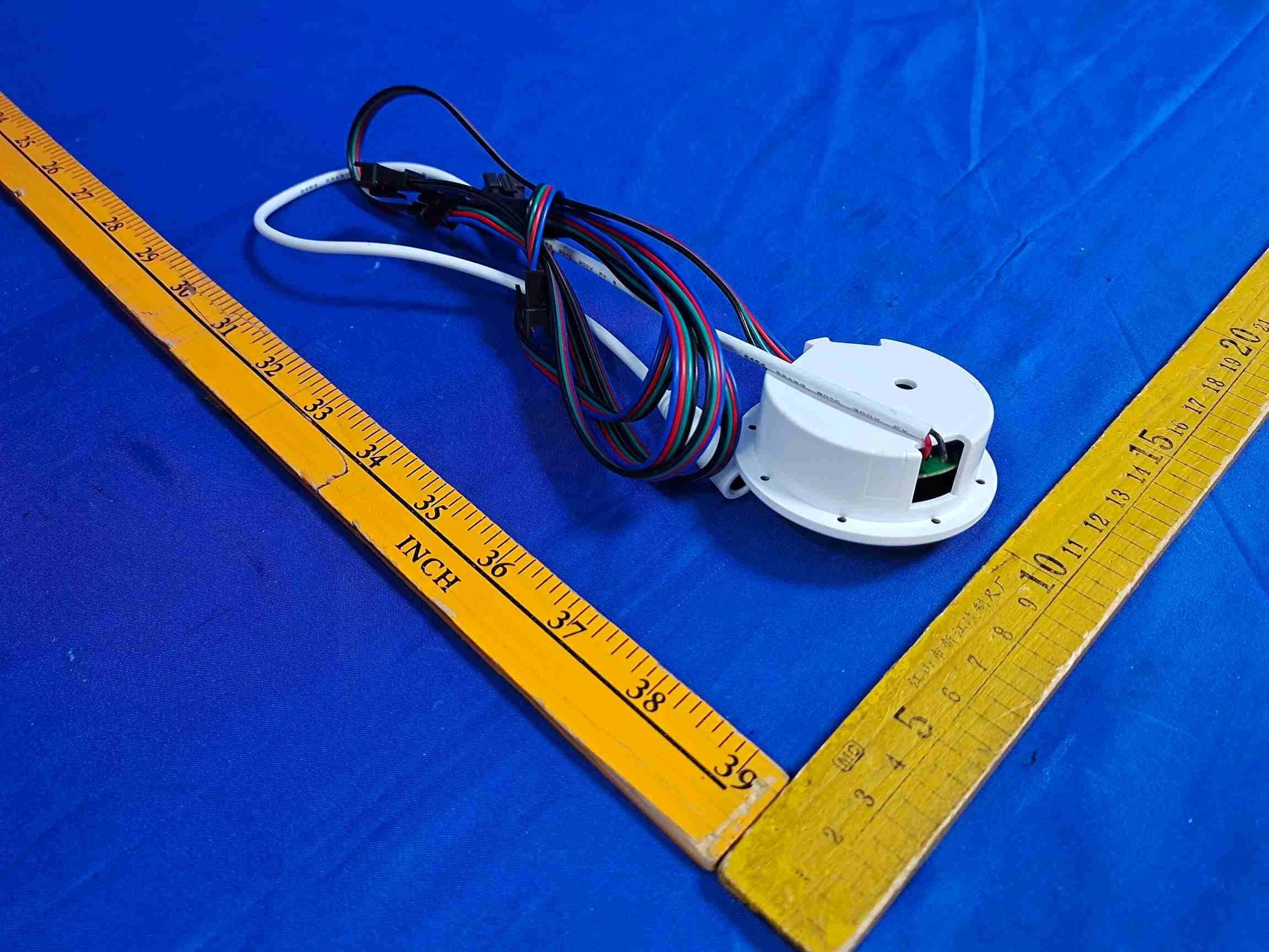
Click to zoom
Application Details
- Equipment Class
- DTS - Digital Transmission System
- Date of Grant
- Aug 12, 2026
- Application Purpose
- Original Equipment
- Equipment Note
- Radar sensor touch LED strip
- Frequency Range
- 2402.00000000 - 2480.00000000
- Country
- China
Documents & Files
Document Text
Text extracted from the exhibit documents filed with the FCC. Open a document above to read the original.
Users Manual
The XY03 RGB Smart Box is equipped with a built-in motion sensor capable of detecting movement within a range of up to 2 meters. When an object or person approaches, the device automatically activates the lighting system for intelligent, hands-free operation. It features RGB multi-color dimming, allowing users to adjust colors and bright- ness to create customized lighting effects. By scanning the QR code to download the dedicated mobile app, users can con- veniently control and personalize lighting functions directly from their smart- RGB Smart BoxUser Manual phone, enabling a fully customized smart lighting experience. Product Introduction XY03APP 1 This touch button enables the LED strip to be turned on and off and to switch between different light colors. A.Each click of this touch button activates 7 static colors and 8 dynamic modes. Note that to turn off the lights, press and hold this touch button; a short press again will restore the LED lights to the mode they were in before being turned off. Operating Instructions (the specific power adapter used may vary depending on the country or region). 2 FCC WARNING: This equipment may generate or use radio frequency energy. Changes or modifications to this equipment may cause harmful interference unless the modifications are expressly approved in the instruction manual. The user could lose the authority to operate this equipment if an unauthorized change or modification is made. This device complies with part 15 of the FCC Rules. Operation is subject to the following two conditions: (1) This device may not cause harmful interference, and (2) this device must accept any interference received, including interference that may cause undesired operation. The device has been evaluated to meet general RF exposure requirement. The device can be used in portable exposure condition without restriction. NOTE: This equipment has been tested and found to comply with the limits for a Class B digital device, pursuant to part 15 of the FCC Rules. These limits are designed to provide reasonable protection against harmful interference in a residential installation. This equipment generates, uses and can radiate radio frequency energy and, if not installed and used in accordance with the instructions, may cause harmful interference to radio communications. However, there is no guarantee that interference will not occur in a particular installation. If this equipment does cause harmful interference to radio or television reception, which can be determined by turning the equipment off and on, the user is encouraged to try to correct the interference by one or more of the following measures: Reorient or relocate the receiving antenna. Increase the separation between the equipment and receiver. Connect the equipment into an outlet on a circuit different from that to which the receiver is connected. Consult the dealer or an experienced radio/TV technician for help. The rating information is located at the bottom of the unit. 3 4 5 6
External Photos
FCCID:2A855-XY03
ID Label/Location Info
LABEL&location
Internal Photos
FCCID:2A855-XY03
RF Exposure Info
Page1of5 RFEXPOSUREEVALUATION FCCID:2A855-XY03 Product:RadarsensortouchLEDstrip ModelName: XY03,XY03B,XY03A Brand: / ReportNo.:PTC26051213902E-FC02 Preparedfor Shenzhenxuxingtechnologyco.,LTD Floor3,buildingC,HuazehitechIndustrial,Park,Shiyanstreet,Bao'anDistrict,Shenzhen, China Preparedby PreciseTesting&CertificationCo.,Ltd. Building1,No.6,TongxinRoad,DongchengStreet,Dongguan,Guangdong,China ReportNo.:PTC26051213902E-FC02 Page2of5 GeneralInformation Applicant’sname: Shenzhenxuxingtechnologyco.,LTD Address: Floor3,buildingC,HuazehitechIndustrial,Park,Shiyanstreet, Bao'anDistrict,Shenzhen,China Manufacture'sname: Shenzhenxuxingtechnologyco.,LTD Address: Floor3,buildingC,HuazehitechIndustrial,Park,Shiyanstreet, Bao'anDistrict,Shenzhen,China ProductName:RadarsensortouchLEDstrip ModelName:XY03,XY03B,XY03A TestModel:XY03 Operatingfrequency:2402-2480MHzForDTS NumbersofChannel:40channelsForDTS AntennaType:PCBAntenna AntennaGain:0dBi TypeofModulation:GFSKForDTS Powersupply:DC12V,2Afromadapter HardwareVersion:N/A SoftwareVersion:N/A TestsampleNo.:PTC26042725801E-1/2,PTC26042725801E-2/2. TestDate:May22,2026toJune19,2026 TestResult:PASS Modeldifference: AllmodelsareidenticaltoeachotherexceptthatthelengthofLED stripandnoadapterformodelXY03BandmodelXY03A. ReportNo.:PTC26051213902E-FC02 Page3of5 TESTFACILITY PreciseTesting&CertificationCo.,Ltd Address:Building1,No.6,TongxinRoad,DongchengStreet,Dongguan,Guangdong, China FCCRegistrationNumber:790290 A2LACertificateNo.:4408.01 ICRegistrationNumber:12191A FCCDesignationNumber:CN1219 ReportNo.:PTC26051213902E-FC02 Page4of5 StandardRequirement Accordingto§15.247(i)and§1.1307b(1),systemsoperatingundertheprovisionsofthis sectionshallbeoperatedinamannerthatensuresthatthepublicisnotexposedtoradio frequencyenergylevelsinexcessoftheCommission’sguidelines.SeeKDB447498D01 GeneralRFExposureGuidancev06,section4.3.1. The1-gand10-gSARtestexclusionthresholdsfor100MHzto6GHzattestseparation distances≤50mmaredeterminedby: [(max.powerofchannel,includingtune-uptolerance,mW)/(min.testseparationdistance, mm)]*[√f(GHz)]≤3.0for1-gSARand≤7.5for10-gSARextremitySAR,where f(GHz)istheRFchanneltransmitfrequencyinGHz PoweranddistanceareroundedtothenearestmWandmmbeforecalculation Theresultisroundedtoonedecimalplaceforcomparison. Thetestexclusionsareapplicableonlywhentheminimumtestseparationdistanceis≤ 50mmandfortransmissionfrequenciesbetween100MHzand6GHz.Whentheminimumtest separationdistanceis<5mm,adistanceof5mmisappliedtodetermineSARtestexclusion. RoutineSARevaluationreferstothatspecificallyrequiredby§2.1093,usingmeasurements orcomputersimulation.WhenroutineSARevaluationisnotrequired,portabletransmitters withoutputpowergreaterthantheapplicablelowthresholdrequireSARevaluationtoquality forTCBapproval. ReportNo.:PTC26051213902E-FC02 Page5of5 RFOutputpower Channel (MHz) Maximum output power (dBm) Tuneup tolerance (dBm) MaxTune UpPower (mW) Distance (mm) Calculation results Limit Operating Mode 24400.30 0.30±1 1.28250.4213DTS-BLE Conclusion: 1.Calculateintheworst-casemode. 2.Max.TuneUpPowerisdeclaredbymanufacturer,andusedtocalculate.
Test Report
Page 1 of 46 FCC TEST REPORT FCC ID: 2A855-XY03 Product: Radar sensor touch LED strip Model Name: XY03, XY03B, XY03A Brand: / Report No.: PTC26051213902E-FC01 Prepared for Shenzhen xu xing technology co., LTD Floor 3, building C, Huaze hi tech Industrial, Park, Shiyan street, Bao'an District, Shenzhen, China Prepared by Precise Testing & Certification Co., Ltd Building 1, No. 6, Tongxin Road, Dongcheng Street, Dongguan, Guangdong, China Report No.: PTC26051213902E-FC01 Page 2 of 46 1 TEST RESULT CERTIFICATION Applicant’s name: Shenzhenxuxingtechnologyco.,LTD Address: Floor3,buildingC,HuazehitechIndustrial,Park,Shiyanstreet, Bao'an District, Shenzhen, China Manufacture's name : Shenzhenxuxingtechnologyco.,LTD Address: Floor3,buildingC,HuazehitechIndustrial,Park,Shiyanstreet, Bao'an District, Shenzhen, China Product name: Radar sensor touch LED strip Model name: XY03, XY03B, XY03A Standards: FCC CFR47 Part 15 Section 15.247 Test procedure: ANSI C63.10:2020 Test Date: May 22, 2026 to June 19, 2026 Date of Issue: June 30, 2026 Test Result: Pass This device described above has been tested by PTC, and the test results show that the equipment under test (EUT) is in compliance with the FCC requirements. And it is applicable only to the tested sample identified in the report. This report shall not be reproduced except in full, without the written approval of PTC, this document may be altered or revised by PTC, personal only, and shall be noted in the revision of the document. Test Engineer: Jack zhou / Engineer Technical Manager: Simon Pu / Manager Report No.: PTC26051213902E-FC01 Page 3 of 46 Contents Page 1 TEST RESULT CERTIFICATION...............................................................................................................................2 2 TEST SUMMARY..........................................................................................................................................................5 2.1 T EST S ITE ............................................................................................................................................................6 3 GENERAL INFORMATION.......................................................................................................................................7 3.1 G ENERAL D ESCRIPTION OF E.U.T.....................................................................................................................7 3.2 C HANNEL L IST .....................................................................................................................................................8 4 EQUIPMENT DURING TEST....................................................................................................................................9 4.1 E QUIPMENTS L IST .............................................................................................................................................9 4.2 M EASUREMENT U NCERTAINTY .........................................................................................................................11 4.3 D ESCRIPTION OF S UPPORT U NITS ...................................................................................................................12 5 CONDUCTED EMISSION..........................................................................................................................................13 5.1 E.U.T. O PERATION ............................................................................................................................................13 5.2 EUT S ETUP .......................................................................................................................................................13 5.3 T EST SET-UP (B LOCK D IAGRAM OF C ONFIGURATION ).................................................................................14 5.4 M EASUREMENT P ROCEDURE ............................................................................................................................14 5.5 C ONDUCTED E MISSION L IMIT ...........................................................................................................................14 5.6 M EASUREMENT D ESCRIPTION ..........................................................................................................................14 5.7 C ONDUCTED E MISSION T EST R ESULT .............................................................................................................14 6 RADIATED SPURIOUS EMISSIONS......................................................................................................................17 6.1 EUT O PERATION ...............................................................................................................................................17 6.2 T EST S ETUP ......................................................................................................................................................18 6.3 S PECTRUM A NALYZER S ETUP ..........................................................................................................................19 6.4 T EST P ROCEDURE .............................................................................................................................................20 6.5 S UMMARY OF T EST R ESULTS ...........................................................................................................................22 7 CONDUCT BAND EDGE AND SPURIOUS EMISSIONS MEASUREMENT....................................................29 7.1 T EST P ROCEDURE .............................................................................................................................................29 7.2 T EST S ETUP ......................................................................................................................................................29 7.3 T EST R ESULT .......................................................................................…
Text truncated - open the document above for the full version.
Test Report
Antenna describe 1. Antenna describe: Antenna plate PCB ANTENNA Make name/model name PDT-002 Antenna gain 0dBi Frequency range 2.4GHZ-2.483GHZ Connector type direct Manufacturer Name: DONGGUANG XIAOKE INDUSTRLES.CO.,LTD Manufacture Address: NO. 227, DONGCHENG SECTION, GUANDONG ROAD, DONGCHENG STREET, DONGGUAN CITY,CHINA 2.External view drawing: Picture of antenna Antenna Dimensions L1 2.15 mm L2 1.20 mm L3 1.95 mm W1 0.35 mm W2 0.35 mm D1 1.25 mm D2 1.65 mm D3 0.50 mm 3.Antenna Radiation Pattern
Test Setup Photos
FCCID:2A855-XY03 ConductedEmissions RadiatedSpuriousEmissions From30MHz-1000MHz TestfrequencyfromAbove1GHz RFconducted
Contact Information
Applicant
Gui Wu
[email protected]Fax: 86-755-29113135
Technical Contact
Test Firm
Precise Testing & Certification Co., LTD.Yang Juan
Technical Specifications
| # | Rule Parts | Frequency Range | Power Output |
|---|---|---|---|
| 1 | 15C | 2.40 GHz - 2.48 GHz | 1.10 mW |
Other Applications from Shenzhen xu xing technology co., LTD
2A855-5050RGB-60D
Jan 14, 2026XX LED RGB STRIP
Equipment Class
DSC - Part 15 Security/Remote Control Transmitter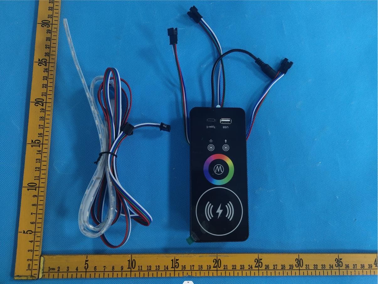
2A855-QHA8
Nov 10, 2022Smart wireless charging case with 24-color light adjustment
Equipment Class
DCD - Part 15 Low Power Transmitter Below 1705 kHz