2A85D-PCT523WiFi Thermostat
Xiamen OWON Technology Co., Ltd.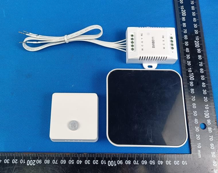
Click to zoom
Application Details
- Equipment Class
- DTS - Digital Transmission System
- Date of Grant
- Sep 08, 2024
- Application Purpose
- Original Equipment
- Date of Application
- Sep 08, 2024
- Equipment Note
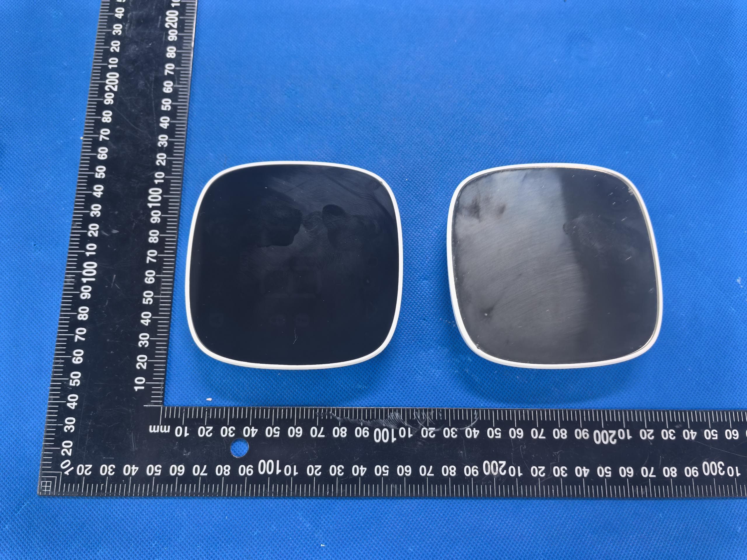
- WiFi Thermostat
- Frequency Range
- 2412.00000000 - 2462.00000000
- Country
- China
Documents & Files
Document Text
Text extracted from the exhibit documents filed with the FCC. Open a document above to read the original.
Users Manual
Wi-Fi Smart Thermostat Quick Start Guide 2 Important Information FAILURE TO FOLLOW THESE SAFETY INSTRUCTIONS COULD RESULT IN FIRE, ELECTRIC SHOCK, OR OTHER INJURY OR DAMAGE. In some regions, a professional installation may be necessary. Check your local regulations and building codes before undertaking any electrical work, as permits and/or professional installation might be legally required. Before starting installation, turn off the power to the installation area at your circuit breaker or fuse box. Always handle electrical wiring with care to avoid the risk of electrical shock or equipment damage. Install your device in a location that is away from heat sources and direct sunlight to prevent temperature fluctuations, which could affect the accuracy of temperature readings and overall device performance. Avoid placing your device near water or in areas with high humidity. 3 In the box Wi-Fi Thermostat C-wire Power Module (optional) Remote Zone Sensor (optional) Trim PlateBackplate User GuidePhillips screwdriver Flat head screwdriver Screws (x2) Drywall Plugs (x2) Wire Labels To Thermostat RGYW RGCYW To Control Board 4 A pencil Pliers and wire strippers A drill with a 3/16-inch drill bit These tools will help with installation 5 Step 1. Turn off the power Locate the power switch for the HVAC system and turn it off. This step is important for your safety and the safety of your home. Once the power is off, try adjusting your old thermostat to double check that the system is off. Step 2. Remove your old thermostat faceplate Some faceplate can be easily pop off, while others require a screwdriver. ON OFF 6 Step 3. Compatibility Check A. High Voltage or or B. C-wire If you see any of these indicators on the back of your old thermostat, it indicates that your system is high voltage, which may not be compatible. • The thermostat requires a C wire for power. Check if there is a wire connected to the C terminal on your old thermostat. • If you don't have a C wire, you will need the following 3 wires on your old thermostat to install the C-wire power module to power new thermostat: Y/Y1, G, and R (or Rc or Rh) If you have neither a C wire nor the three required wires mentioned above, then your system is incompatible. 110VAC 120VAC 240VAC L1L2 RC RH G C O/B 7 Step 4. Take a photo of your old wiring It's important to have a photo of your old wiring, just in case you need to return the wiring to the way it was before. Step 5. Remove all jumper wires Some systems have short wires connecting two terminals. One of the two terminals may not have a wire coming trom the wall. Remove all jumper wires. Be careful not to remove regular wires coming from the wall. RC RH G C O/B RC RH G C O/B RC RH G C O/B RC RH G C O/B 8 Step 6. Check which set of labels you will be using Some thermostats have 2 sets of terminal labels, one for heat pump and one for conventional. If you only have one set of labels, please skip this step and jump to page 10. • If your system has a heat pump, please use the heat pump wire labels or the set of wires that includes the "O/B" label. • If your system does not have a heat pump, please use the conventional wire labels or the set of wires without the "O/B" label. Y2 L W2 AUX/E G G W O/B C C Y Y R R RCConventional Heat Pump RC Y2 L W2 AUX/E G G W O/B C C Y Y R R RCConventional Heat Pump RC L AUX/E GO/BCYR Heat Pump RC Y2 L W2 AUX/E G G W O/B C C Y Y R R RCconventional Heat Pump RC Y2W2GWCYRRCConventional 9 • If it is orange, please use the heat pump wire labels or the set of wires that includes the "O/B" label. • If it is white, please use the conventional wire labels or the set of wires without the "O/B" label. You can also identify it by the colors of wire with W and O/B labels. Y2 L W2 AUX/E G G W O/B C C Y Y R R RCConventional Heat Pump RC L AUX/E GO/BCYR Heat Pump RC Y2 L W2 AUX/E G G W O/B C C Y Y R R RCconventional Heat Pump RC Y2W2GWCYRRCConventional Y2 L W2 AUX/E G G W O/B C C Y Y R R RCConventional Heat Pump RC W O/B 10 Special labels: If your old thermostat has wires connected to the following terminals, you need to pay special attention when tagging them: TerminalTerminalLabelsLabels W2/Aux W2/Aux W1 W2 W1 W2 Aux or Aux1 Aux2 Step 7. Label your wires Use the provided Wire Labels (White background) to tag each wire accordingly. If you have two sets of terminal labels, please select the correct one. If you are Heat Pump systemIf you are Conventional system RC RH G C O/B Rc G Y� W� C 11 Do you see any wire connected to the C terminal on your old thermostat? CHECKPOINT: C-WIRE Continue to the NEXT PAGE Go to PAGE 18 YES NO RC RH G C O/B 12 Install the thermostat with a C wire Step 8. Disconnect wires Loosen each terminal and disconnect the wires from your old thermostat. Don't let your wiring fall back into the wall after you disconnect them. Step 9. Remove your old wall plate Unscrew the old thermostat from the wall. If your old thermostat has a trim plate, remove it too. You may want to wrap the wires around a pencil so they don't fall back into the wall. RC RH G C O/B RC RH G C O/B Rc G Y1 W1 C Rc G Y1 W1 C 13 Step 10. Pull the wires through the backplate Mark where the screws will go. Use the bubble level to make sure the thermostat is straight. If you need to drill new holes in your wall, remove the backplate before doing so. Step 11. Attach the backplate to the wall Secure your new thermostat's backplate to the wall by using the included anchors and screw. You can drill a hole for the drywall anchors with 3/16' drill bit. Optional: use the trim plate to cover screw holes or gaps left over from your old thermostat's installation. Rc Y1 Y2 O/B G C Rh W1 W2 S Rc Y1 Y2 O/B G C Rh W1 W2 S 14 Step 12. Connect the wires Press the terminal block levers down to insert each labelled wire to the matching slot in your backplate. You can refer to the wiring diagram on page 29 Tug on the wires gently to ensure they are secured. After all the wires are inserted, tuck them neatly back int…
Text truncated - open the document above for the full version.
Attestation Statements
1/1 US Agent for Service of Process LETTER OF ATTESTATION TO: Office of Engineering Technology Federal Communications Commission 7435 Oakland Mills Road Columbia, MD 21046 US Agent for Service of Process: Company Name: REP America LLC FRN: 0034192500 Contact Name: Ben XU Address: Address: 6510 S Academy Blvd, Ste A #523, Colorado Springs, CO 80906 Telephone No: 719 201 3314 Email: [email protected] Applicant: Company name: Xiamen OWON Technology Co., Ltd. Product Description: WiFi Thermostat Grantee code: 2A85D FCC ID: 2A85D-PCT523 FRN: 0033032061 Contact Name: Simon Lin Address: Rm501, Tower C07, Softpark Phase 3, Jimei, Xiamen, Fujian, China Telephone No: 0592-2520380 Fax No: / Email: [email protected] [Xiamen OWON Technology Co., Ltd.] certifies that, as of the date of this filing of the application with the TCB, [REP America LLC] is our designated US agent for service of process for the above referenced FCC ID. [Xiamen OWON Technology Co., Ltd.] accepts to maintain an agent for no less than one year after the grantee has terminated all marketing and importation or the conclusion of any commission related proceeding involving equipment. [REP America LLC] accepts, as of the date of the filing of the application, the obligation of the designated US agent for service of process for the above reference FCC ID. The US Agent for Service of Process is aware of and agrees to comply with the requirements outlined in the FCC Equipment Authorization Program, Report and Order FCC 22-84, and clause § 2.911. The Applicantis aware of and agrees to comply with the requirements outlined in the FCC Equipment Authorization Program, Report and Order FCC 22-84, and clause § 2.911. Date: 2024/09/04 Applicant’s Name: Simon Lin US Agent’s Name: Ben XU Title: Manager Title: President Signature Signature
Attestation Statements
C5266091_X24_Ed.2 1/1 “Attestation Statements” TO: Office of Engineering Technology Federal Communications Commission 7435 Oakland Mills Road Columbia, MD 21046 The Commission adopted rules that prohibit equipment authorization for “covered” telecommunications equipment and video surveillance equipment produced by entities identified on the Commission’s Covered List 1 , which is periodically updated. See the Covered List for more details. This Attestation Statement is to confirm that we follow the Section 2.911(d)(5)(i)-(ii) Applicant Company name: Xiamen OWON Technology Co., Ltd. Grantee code: 2A85D FRN: 0033032061 FCC ID: 2A85D-PCT523 Contact Name: Simon Lin Address: Rm501, Tower C07, Softpark Phase 3, Jimei, Xiamen, Fujian, China Telephone No: 0592-2520380 Fax No: / Email: [email protected] i. [Xiamen OWON Technology Co., Ltd.] (“the applicant”) certifies that the equipment for which authorization is sought is not “covered” equipment prohibited from receiving an equipment authorization pursuant to section 2.903 of the FCC rules. The applicant must sign this certification. ii. [Xiamen OWON Technology Co., Ltd.]] (“the applicant”) certifies that, as of the date of the filing of the application, the applicant [is not](as a specifically named entity or any of its subsidiaries or affiliates)identified on the Covered List as an entity producing “covered” equipment. Theapplicantmustsignthiscertification. [Xiamen OWON Technology Co., Ltd.] (“the applicant”) certifies that, as of the date of the filing of theapplication, the applicant [is not] identified on the Covered List as an entity producing “covered”equipment . Date: 2024/09/04 Applicant’s Name: Simon Lin Title: Manager Signature 1 The Commission’s Covered List is published by the Public Safety and Homeland Security Bureau and posted on the Commission’s website. This Covered List, which is periodically updated, identifies particular equipment, produced by particular entities, that constitutes “covered” equipment. https://www.fcc.gov/supplychain/coveredlist
Attestation Statements
Xiamen OWON Technology Co., Ltd. Product Similarity Declaration Product name: WiFi Thermostat Model name: PCT 523-W-TY, PCT 523E-W-TY, PCT 523U-W-TY, EHVC523, EHVC523E, EHVC523U, STC-200, STC-210, SCT-220, PCT 523-W-TY/XX, PCT 523E-W-TY/XX, PCT 523U-W-TY/XX, The first X stands for A-Z, and the second X stands for A-Z FCC ID:2A85D-PCT523 We (Xiamen OWON Technology Co., Ltd.) hereby state that all the models are electrical identical including the same software parameter and hardware design (i.e., circuit design, PCB Layout, RF module/circuit, antenna type(s) and antenna location, components on PCB, etc.,), same mechanical structure and design (including product enclosure, materials, etc.,), the only difference is the model name and color. Signature: Name: : Simon Lin Date: 2024-09-04 Title: Mananger Signature of applicant:
Cover Letter(s)
C5266091_X8_Ed.1 1/1 Letter of Authorization Xiamen OWON Technology Co., Ltd. Company: Xiamen OWON Technology Co., Ltd. Address: Rm501, Tower C07, Softpark Phase 3, Jimei, Xiamen, Fujian, China Product Name: WiFi Thermostat Model Number: PCT 523-W-TY, PCT 523E-W-TY, PCT 523U-W-TY, EHVC523, EHVC523E, EHVC523U, STC-200, STC-210, SCT-220, PCT 523-W-TY/XX, PCT 523E-W-TY/XX, PCT 523U-W-TY/XX, The first X stands for A-Z, and the second X stands for A-Z FCC Identifier: 2A85D-PCT523 We authorize LGAI Technological Center S.A., Ronda de la Font del Carme, s/n, 08193 Bellaterra, Spain, to act on our behalf on all matters concerning the above named equipment. Any individual within LGAI Technological Center S.A. is authorized to act on our behalf and take action on the application. We declare that authorize LGAI Technological Center S.A., Ronda de la Font del Carme, s/n, 08193 Bellaterra, Spain, is allowed to forward all information related to the approval project to the Federal Communication Commission and to discuss any issues concerning the approval application. Any and all acts carried out by LGAI Technological Center S.A. on our behalf shall have the same effect as acts of our own. Signature: Name: : Simon Lin Date: 2024-09-04 Title: Mananger Signature of applicant:
Cover Letter(s)
C5266091_X10_Ed.2 1/1 Xiamen OWON Technology Co., Ltd. Office of Engineering Technology Federal Communications Commission 7435 Oakland Mills Road Columbia, MD 21046 Date: 2024-09-04 Subject: Request for Confidentiality FCC ID: 2A85D-PCT523 To Whom It May Concern, Pursuant to the provisions of Sections 0.457 and 0.459 of Commission's rules (47CFR0.457, 0.459), we are requesting the Commission to withhold the following attachment(s) as confidential document from public disclosure. Exhibits Long-Term Confidentiality Short-Term Confidentiality NOTE 2 ID Label/Location No No Attestation Statement No No External Photos No ☐ Block Diagram ■ ☐ Schematics ■ ☐ Test Report No No Test Setup Photos No ☐ User’s Manual ☐ NOTE 1 ☐ Internal Photos ☐ NOTE 1 ☐ Parts List / Tune Up ☐ ☐ RF Exposure Info No No Operational Description ■ ☐ Cover Letter(s) No No SDR Software / Security Info ☐ No NOTE 1: Long-Term Confidentiality may be permitted under special conditions (See II. LONG-TERM CONFIDENTIALITY, Section 3 of KDB 726920, use last in force) NOTE 2: Short-Term Confidentiality can be requested for a maximum of 180 days from the date of the grant. Above mentioned document contains detailed system and equipment description are considered as proprietary information in operation of the equipment. The public disclosure of above documents might be harmful to our company and would give competitor an unfair advantage in the market. In case of short-term Confidentiality, the applicant requests the exhibits selected above are withheld from public view for a period of ______ days from the date of the Grant of Equipment Authorization and prior to marketing. It is our understanding that all measurement test reports, FCC ID label format and correspondent during certification review process cannot be granted as confidential documents and those information will be available for public review once the grant of equipment authorization is issued. C5266091_X10_Ed.2 1/1 Signature: Name: : Simon Lin Date: 2024-09-04 Title: Mananger Signature of applicant:
External Photos
Page 1 of 4 Shenzhen NCT Testing Technology Co., Ltd. A101&2F B2, Fuqiao 6th Area, Xintian Community, Fuhai Street, Baoan District, Shenzhen, China Hotline: 400-8868-419 Fax: 86-755-27790922 http://www.ncttesting.cn FCC ID:2A85D-PCT523 External Photos Page 2 of 4 Shenzhen NCT Testing Technology Co., Ltd. A101&2F B2, Fuqiao 6th Area, Xintian Community, Fuhai Street, Baoan District, Shenzhen, China Hotline: 400-8868-419 Fax: 86-755-27790922 http://www.ncttesting.cn Page 3 of 4 Shenzhen NCT Testing Technology Co., Ltd. A101&2F B2, Fuqiao 6th Area, Xintian Community, Fuhai Street, Baoan District, Shenzhen, China Hotline: 400-8868-419 Fax: 86-755-27790922 http://www.ncttesting.cn Label&location Page 4 of 4 Shenzhen NCT Testing Technology Co., Ltd. A101&2F B2, Fuqiao 6th Area, Xintian Community, Fuhai Street, Baoan District, Shenzhen, China Hotline: 400-8868-419 Fax: 86-755-27790922 http://www.ncttesting.cn
ID Label/Location Info
FCC ID LABELING AND LOCATION FCC ID Label FCC ID: 2A85D-PCT523 FCC ID Label Location The label shown shall be permanently affixed at a conspicuous location on the device and be readily visible to the user at the time purchase (Labeling requirements per 2.925)
Internal Photos
Page 1 of 6 Shenzhen NCT Testing Technology Co., Ltd. A101&2F B2, Fuqiao 6th Area, Xintian Community, Fuhai Street, Baoan District, Shenzhen, China Hotline: 400-8868-419 Fax: 86-755-27790922 http://www.ncttesting.cn FCC ID:2A85D-PCT523 Internal Photos Page 2 of 6 Shenzhen NCT Testing Technology Co., Ltd. A101&2F B2, Fuqiao 6th Area, Xintian Community, Fuhai Street, Baoan District, Shenzhen, China Hotline: 400-8868-419 Fax: 86-755-27790922 http://www.ncttesting.cn Page 3 of 6 Shenzhen NCT Testing Technology Co., Ltd. A101&2F B2, Fuqiao 6th Area, Xintian Community, Fuhai Street, Baoan District, Shenzhen, China Hotline: 400-8868-419 Fax: 86-755-27790922 http://www.ncttesting.cn Page 4 of 6 Shenzhen NCT Testing Technology Co., Ltd. A101&2F B2, Fuqiao 6th Area, Xintian Community, Fuhai Street, Baoan District, Shenzhen, China Hotline: 400-8868-419 Fax: 86-755-27790922 http://www.ncttesting.cn PCB ANT Page 5 of 6 Shenzhen NCT Testing Technology Co., Ltd. A101&2F B2, Fuqiao 6th Area, Xintian Community, Fuhai Street, Baoan District, Shenzhen, China Hotline: 400-8868-419 Fax: 86-755-27790922 http://www.ncttesting.cn Page 6 of 6 Shenzhen NCT Testing Technology Co., Ltd. A101&2F B2, Fuqiao 6th Area, Xintian Community, Fuhai Street, Baoan District, Shenzhen, China Hotline: 400-8868-419 Fax: 86-755-27790922 http://www.ncttesting.cn
RF Exposure Info
FCC ID:2A85D-PCT523 RF Exposure Evaluation According to KDB 447498 D01 General RF Exposure Guidance v06 and part 2.1091,Unless specifically required by the published RF exposure KDB procedures, standalone 1-g head or body and 10-g extremity SAR evaluation for general population exposure conditions, by measurement or numerical simulation, is not required when the corresponding SAR Test Exclusion Threshold condition(s), listed below, is (are) satisfied. Limits The criteria listed in the following table shall be used to evaluate the environment impact of human exposure to radio frequency (RF) radiation as specified in 1.1307(b) Limits for Maximum Permissible Exposure (MPE) Frequency range (MHz) Electric field strength (V/m) Magnetic field strength (A/m) Power density (mW/cm 2 ) Averaging time (minutes) (A) Limits for Occupational/Controlled Exposures 0.3–3.0 614 1.63 *(100) 6 3.0–30 1842/f 4.89/f *(900/f 2 ) 6 30–300 61.4 0.163 1.0 6 300–1500 f/300 6 1500–100,000 5 6 (B) Limits for General Population/Uncontrolled Exposure 0.3–1.34 614 1.63 *(100) 30 1.34–30 824/f 2.19/f *(180/f 2 ) 30 30–300 27.5 0.073 0.2 30 300–1500 f/1500 30 1500–100,000 1.0 30 f = frequency in MHz Friis transmission formula: Pd = (Pout*G)/(4*pi*r 2 ) Where Pd = power density in mW/cm 2 , Pout = output power to antenna in mW; G = gain of antenna in linear scale, Pi = 3.1416; R = distance between observation point and center of the radiator in cm Pd id the limit of MPE, 1 mW/cm 2 . If we know the maximum gain of the antenna and the total power input to the antenna, through the calculation, we will know the distance r where the MPE limit is reached. Test Procedure Software provided by client enabled the EUT to transmit and receive data at lowest, middle and highest channel individually. Test Result of RF Exposure Evaluation Remark:1. wifi2.4G Antenna gain is 1.37dBi The Max Calc. Thresholds : 0.0109≤ 1 So a SAR test is not required Modulation Frequenc y MHz Output power to antenna (dBm) Target power W/toler ance (dBm) Max Output power to antenna (dBm) Max Output power to antenna (mW) Power Density at R=20cm (mW/cm2) Limit (mW/c m2) Result WIFI 2.4G 802.11b 2412 15.47 15±1 16 39.811 0.0109 1.0 PASS 2437 15.11 15±1 16 39.811 0.0109 1.0 PASS 2462 15.09 15±1 16 39.811 0.0109 1.0 PASS 802.11g 2412 14.36 14±1 15 31.623 0.0086 1.0 PASS 2437 14.25 14±1 15 31.623 0.0086 1.0 PASS 2462 13.88 13±1 14 25.119 0.0068 1.0 PASS 802.11n (HT20) 2412 13.98 13±1 14 25.119 0.0068 1.0 PASS 2437 13.73 13±1 14 25.119 0.0068 1.0 PASS 2462 13.61 13±1 14 25.119 0.0068 1.0 PASS 802.11n (HT40) 2422 13.07 13±1 14 25.119 0.0068 1.0 PASS 2437 12.67 12±1 13 19.953 0.0054 1.0 PASS 2452 12.46 12±1 13 19.953 0.0054 1.0 PASS
Test Report
FCC TEST REPORT FCC ID:2A85D-PCT523 Product : WiFi Thermostat Model Name : PCT 523-W-TY, PCT 523E-W-TY, PCT 523U-W-TY, EHVC523, EHVC523E, EHVC523U, STC-200, STC-210, SCT-220, PCT 523-W-TY/XX, PCT 523E-W-TY/XX, PCT 523U-W-TY/XX, The first X stands for A-Z, and the second X stands for A-Z Brand : N/A Report No. : NCT24034451E Prepared for Xiamen OWON Technology Co., Ltd. Rm501, Tower C07, Softpark Phase 3, Jimei, Xiamen, Fujian, China Prepared by Shenzhen NCT Testing Technology Co., Ltd. A101&2F B2, Fuqiao 6th Area, Xintian Community, Fuhai Street, Baoan District, Shenzhen, People’s Republic of China TEL: 400-8868-419 FAX: 86-755-27790922 Report No.: NCT24034451E Page 2 of 66 Hotline: 400-8868-419 Fax: 86-755-27790922 http://www.ncttesting.cn 1 TEST RESULT CERTIFICATION Applicant : Xiamen OWON Technology Co., Ltd. Address : Rm501, Tower C07, Softpark Phase 3, Jimei, Xiamen, Fujian, China Manufacturer : ZHANGZHOU LILLIPUT ELECTRONIC TECHNOLOGY CO., LTD Address : Fuqibei Road 26, Lan Tian Economic Development Zone, Zhang Zhou, Fu Jian, 363005, China Product name : WiFi Thermostat Model name : PCT 523-W-TY, PCT 523E-W-TY, PCT 523U-W-TY, EHVC523, EHVC523E, EHVC523U, STC-200, STC-210, SCT-220, PCT 523-W-TY/XX, PCT 523E-W-TY/XX, PCT 523U-W-TY/XX, The first X stands for A-Z, and the second X stands for A-Z Standards : FCC CFR47 Part 15 Section 15.247 Test procedure : ANSI C63.10:2013 Date of test : Aug. 15, 2024- Aug. 29, 2024 Date of Issue : Aug. 29, 2024 This device described above has been tested by NCT, and the test results show that the equipment under test (EUT) is in compliance with the FCC requirements. And it is applicable only to the tested sample identified in the report. This report shall not be reproduced except in full, without the written approval of NCT, this document may be altered or revised by NCT, personal only, and shall be noted in the revision of the document. Test Engineer: Keven Wu / Engineer Technical Manager: Henry Wang / Manager Report No.: NCT24034451E Page 3 of 66 Hotline: 400-8868-419 Fax: 86-755-27790922 http://www.ncttesting.cn Contents Page 1 TEST RESULT CERTIFICATION .............................................................................................................................. 2 2 TEST SUMMARY ......................................................................................................................................................... 5 3 GENERAL INFORMATION ........................................................................................................................................ 6 3.1 GENERAL DESCRIPTION OF E.U.T. .................................................................................................................... 6 3.2 CHANNEL LIST .................................................................................................................................................... 7 3.3 TEST SITE ........................................................................................................................................................... 8 3.4 TEST SETUP CONFIGURATION ........................................................................................................................... 9 3.5 TEST MODE ........................................................................................................................................................ 9 4 EQUIPMENT DURING TEST ................................................................................................................................... 10 4.1 EQUIPMENTS LIST ............................................................................................................................................ 10 4.2 MEASUREMENT UNCERTAINTY ......................................................................................................................... 12 4.3 DESCRIPTION OF SUPPORT UNITS ................................................................................................................... 12 5 CONDUCTED EMISSION ......................................................................................................................................... 13 5.1 E.U.T. OPERATION ........................................................................................................................................... 13 5.2 EUT SETUP ...................................................................................................................................................... 13 5.3 TEST SET-UP (BLOCK DIAGRAM OF CONFIGURATION) .................................................................................. 14 5.4 MEASUREMENT PROCEDURE ........................................................................................................................... 14 5.5 CONDUCTED EMISSION LIMIT ........................................................................................................................... 14 5.6 MEASUREMENT DESCRIPTION .......................................................................................................................... 14 5.7 CONDUCTED EMISSION TEST RESULT ............................................................................................................. 14 6 RADIATED SPURIOUS EMISSIONS ..................................................................................................................... 17 6.1 EUT OPERATION .............................................................................................................................................. 17 6.2 TEST SETUP ..................................................................................................................................................... 18 6.3 SPECTRUM ANALYZER SETUP .......................................................................................................................... 19 6.4 TEST PROCEDURE ....................................................................…
Text truncated - open the document above for the full version.
Test Report
1 Antenna Specification Manufacture:TUYA Product Name:CB3S Antenna Antenna Type:PCB Test Date:2021.04.16 Tested by:Jianwei Wang Approved by:Licco Antenna Te s t R e p o r t 2 Content 1.General Description ................................................................................. 3 2.Test Configurations .................................................................................. 4 2.1 Test Environment ............................................................................ 4 2.2 Test Equipment ............................................................................... 4 2.3 Test Principle .................................................................................. 4 3.Test Results .............................................................................................. 5 3.1 Gain and Efficiency ........................................................................ 5 3.2 Radiation Pattern ............................................................................. 6 4.Antenna Dimensions ................................................................................ 9 5.EUT Photo ............................................................................................... 9 6.Test Setup Photo .................................................................................... 10 3 1.General Description Manufacturer Hangzhou Tuya Information Technology Co.,Ltd Address Room 701,Building 3,More Center,No.87 GuDun Road, Hangzhou, Zhejiang,China Test Locat ion Room 106, Building 3, Letong Science Park, No. 500, Qiuyi Road, Binjiang District, Hangzhou Product Name CB3S Antenna Product model CB3S Antenna Type PCB Antenna Test Items Gain; Efficiency; Radiation Pattern Test Frequency 2400-2500MHz Test Standard ANSI/IEEE Std 149-1979 4 2.Test Configurations 2.1 Test Environment Temperature ()°C 25 Humidity (%RH) 60 Atmospheric Pressure (kPa) 100.5 2.2 Test Equipment Test System TEM 24 Multi-probe Microwave Chamber Test Instrument Agilent E5071B 2.3 Test Principle 5 3.Test Results 3.1 Gain and Efficiency Frequency (MHz) Peak Gain (dBi) Efficiency (%) 2400 0.46 44.36 2410 0.71 45.71 2420 0.92 45.92 2430 0.91 45.6 2440 0.95 45.6 2450 0.93 45.29 2460 1.27 46.45 2470 1.37 46.88 2480 1.25 47.21 2490 1.24 46.67 2500 1.05 44.87 6 3.2 Radiation Pattern Phi 0 7 Phi 90 8 Theta 90 9 4.Antenna Dimensions 5.EUT Photo 10 6.Test Setup Photo
Test Setup Photos
Page 1 of 2 Shenzhen NCT Testing Technology Co., Ltd. A101&2F B2, Fuqiao 6th Area, Xintian Community, Fuhai Street, Baoan District, Shenzhen, China Hotline: 400-8868-419 Fax: 86-755-27790922 http://www.ncttesting.cn FCC ID:2A85D-PCT523 Test Photo Page 2 of 2 Shenzhen NCT Testing Technology Co., Ltd. A101&2F B2, Fuqiao 6th Area, Xintian Community, Fuhai Street, Baoan District, Shenzhen, China Hotline: 400-8868-419 Fax: 86-755-27790922 http://www.ncttesting.cn
Contact Information
Applicant
Simon Lin(Manager)
Technical Contact
Test Firm
SHENZHEN NCT TESTING TECHNOLOGY CO., LTD.Henry Wang
[email protected]0755-27790922
Technical Specifications
| # | Rule Parts | Frequency Range | Power Output |
|---|---|---|---|
| 1 | 15C | 2.41 GHz - 2.46 GHz | 35.00 mW |
Other Applications from Xiamen OWON Technology Co., Ltd.
2A85D-PCT5231-W-TY
Apr 30, 2026WiFi Thermostat
Equipment Class
DTS - Digital Transmission System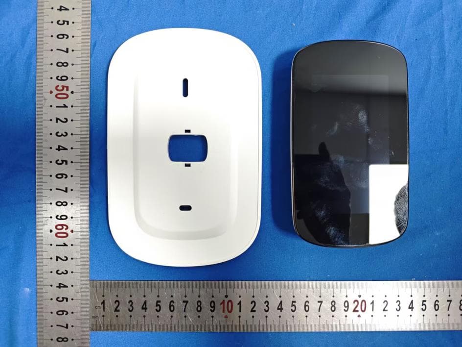
2A85D-PCT533-W-TY
Dec 22, 2025WiFi Thermostat
Equipment Class
DTS - Digital Transmission System2A85D-PC311
Jan 16, 2024Power Clamp
Equipment Class
DTS - Digital Transmission System