2A85W-100Skylight
LEADER ELECTRONICS INC.LEADER ELECTRONICS INC.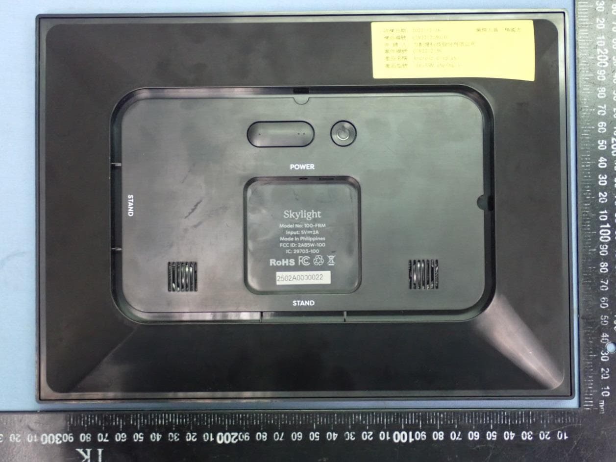
Click to zoom
Application Details
- Equipment Class
- NII - Unlicensed National Information Infrastructure TX
- Date of Grant
- Mar 24, 2023
- Application Purpose
- Original Equipment
- Date of Application
- Mar 23, 2023
- Equipment Note
- Skylight
- Frequency Range
- 5745.00000000 - 5825.00000000
- Country
- Taiwan
Documents & Files
Document Text
Text extracted from the exhibit documents filed with the FCC. Open a document above to read the original.
Users Manual
Features At A Glance Multiple Calendar Views See your events in a day, week, month, or schedule view by selecting a view in the top left-hand corner of your Calendar. Customize your schedule view in Settings to configure the number of days displayed at a time. Color Coding Create categories to organize events by person (ie. Mom’s Calendar) or by category (ie. Soccer Practice). Assign labels and colors to each category. Tap an event to reassign its category. Customizable Lists Create, view, and customize Shopping, To-do, and Other lists (ie. Packing List). Organize your lists by assigning each list a color. Start by tapping the lists button on the home screen. Chore Chart Manage daily chore and task progress for the whole household. Start by tapping the Chore view. R1 删除内容,调整页面大小 R2 更新文件 OFFSET 4 COLOR CYAN MAGENTA YELLOW BLACK DIE LINE PRO CES S NO PRINT Skylight_Cal_QSGuide_R2 4 = CMYK D22110039 Jem 2022.12.12 +/- 1mm 282mm 191mm Contents of the box • Skylight Calendar • Base Mount • Stand & Screws (a & b ) • Wall Mount & Screws (c ) • Power Cable Start Guide Getting Started 2 Connect to Witfi 2 Activate 3 Sync 3 Need Some Help? 4 Getting Started 1. Plug the power adapter into an outlet Plug the round end of the cord into the port on the back of your Calendar marked ‘POWER’. Insert the stand into the slot marked ‘STAND’ to place the device in landscape orientation. 2. Download the Skylight app Search “Skylight App” in your app store or scan the QR code below. With the app, you can sync your calendars, view your events, and more. Scan to download Connect to WiFi 1. Select your network A list of available Witfi networks will appear on the right side of the screen. Tap to choose your network from the list. Swipe up if the list is long. If your network does not appear, wait for 30 seconds and check once more. 2. Enter your password If your Witfi requires a password, a prompt will appear. Type in your password using the onscreen keyboard. 2 Activate 1. Create your Calendar’s email address Download the app or visit ourskylight.com/finalstep to make an account and activate your Calendar. Make sure you select Calendar for device type. 2. Use your code Once you have created your Calendar’s email address, our system will give you a 6-digit code. Enter this code on your Calendar using the on-screen keyboard. 3. Configure Settings Access your Calendar’s settings by tapping on the gear icon to find your device’s email address and configure your device. Sync Sync Online Calendars Sync your Skylight Calendar with your existing calendars (i.e. Google, Apple, Cozi, Outlook) using your account credentials or the online calendar’s public URL in the mobile app or on app.ourskylight.com. Any changes made on your online calendars will automatically reflect on your Skylight Calendar. Create Events Create events directly on your Skylight Calendar by pressing the “+” button or in our app. Send Individual Events Invite your unique Calendar email address (ie. cal-name@ourskylight. com) as an attendee to any event. 3 Need Help? If you have any questions about how to use or set up your Skylight Calendar, please visit our User Guide at skylightframe. com/support. Or contact us at [email protected] Make sure to download the Skylight app to get the most out of your Calendar! Scan to download 4 RF Exposure Statement This equipment complies with the FCC RF radiation exposure limits set forth for an uncontrolled environment. This equipment should be installed and operated with a minimum distance of 20cm between the radiator and any part of your body. This equipment meets the exemption from the routine evaluation limits in section 2.5 of RSS-102. It should be installed and operated with a minimum distance of 20cm between the radiator and any part of your body. Cet é quipement est conforme à l’exemption des limites d’évaluation habituelle de la section 2.5 de la norme RSS-102. Il doit être installé et utilisé à une distance minimale de 20 cm entre le radiateur et toute partie de votre corps. FCC Warning This device complies with Part 15 of the FCC Rules. Operation is subject to the following two conditions: (1) This device may not cause harmful interference, and (2) this device must accept any interference received, including interference that may cause undesired operation. NOTE 1: This equipment has been tested and found to comply with the limits for a Class B digital device, pursuant to part 15 of the FCC Rules. -ese limits are designed to provide reasonable protection against harmful interference in a residential installation. -is equipment generates uses and can radiate radio frequency energy and, if not installed and used in accordance with the instructions, may cause harmful interference to radio communications. However, there is no guarantee that interference will not occur in a particular installation. If this equipment does cause harmful interference to radio or user is encouraged to try to correct the interference by one or more of the following measures: - Reorient or relocate the receiving antenna. - Increase the separation between the equipment and receiver. which the receiver is connected. -Consult the dealer or an experienced radio/TV technician for help. NOTE 2: Any changes or modifications to this unit not expressly approved by the party responsible for compliance could void the user’s authority to operate the equipment” IC Warning This device contains licence-exempt transmitter(s) that comply with Innovation, Science and Economic Development Canada’s licence-exempt RSS(s). Operation is subject to the following two conditions: (1) This device may not cause interference. (2) This device must accept any interference, including interference that may cause undesired operation of the device. L’émetteur/récepteur exempt de licence contenu dans le présent appareil est conforme aux CNR d’Innovation, Sciences et Développement économique Canada applicables aux appareils radio exempts de licence. L’exploitation …
Text truncated - open the document above for the full version.
Users Manual
tfor more Skylight products, visit www.skylightframe.com R1 删除内容,调整文档尺寸 R2 更改内容 R3 更改内容 OFFSET 4 COLOR CYAN MAGENTA YELLOW BLACK DIE LINE PROCESS NO PRINT Skylight_Frame_QSGuide_01_G_R3 4 = CMYK D22110039 Jem 2022.12.12 +/- 1mm 282mm 141mm 141mm Frame Quick Start Guide 191mm Contents of the box • Skylight Frame • Base Mount • Stand & Screws (a & b ) • Wall Mount & Screws (c ) • Power Cable Features Features At A Glance 2 Send Photos 2 Swipe 2 Zoom 2 Heart Button 2 WiFi 2 Skylight Plus 3 Instructions Getting Started 4 Connect to WiFi 4 Activate 5 Share 5 Settings 6 Need Some Help? 7 Features At A Glance Send Photos Use the Skylight app to send dozens of photos at once or attach up to 25MB of photos when emailing to your unique Skylight email address, and the photos will automatically appear on your tframe. Swipe When photos arrive, they’ll play in a slideshow. Swipe to view additional photos. Zoom To zoom into a photo so it fills the screen, take two fingers (e.g. your two index fingers), and pinch to zoom. Heart Button If you love a photo, tap the heart button in the lower-right corner of the screen, and we’ll email the sender to tell them you loved it! You can also hide the heart button by going to Settings > Advanced tfeatures. WiFi Skylight requires Witfi for initial setup and to receive new photos, but you can still view new photos without a Witfi connection. 2 Skylight Plus can also be purchased in-app or at www.skylightframe.com/plus. Skylight Plus If you have purchased the Skylight Plus plan, you can manage all of the tframes under your account and gain access to these premium features: Mobile App Additional access to view photo history and control your tframe remotely, and more. Albums Create, edit, and view photo albums in the app and on your tframe. Videos Send videos to your tframe via email, mobile app, or Skylight Web (app.ourskylight.com). Video sound can be enabled on your tframe. Captions Send photos with captions using the app or Skylight Web. 3 Getting Started 1. Plug the power adapter into an outlet Plug the round end of the cord into the port on the back of your tframe marked ‘POWER’. Insert the stand into one of two slots marked ‘STAND’, pushing firmly. 2. Download the Skylight app Search “Skylight App” in your app store or scan the QR code below. With the app, you can view and send photos from your tframe, like and comment on photos, and more. Scan to download Connect to WiFi 1. Select your network A list of available Witfi networks will appear on the right side of the screen. Tap to choose your network from the list. Swipe up if the list is long. If your network does not appear, wait for 30 seconds and check once more. 2. Enter your password If your Witfi requires a password, a prompt will appear. Type in your password using the onscreen keyboard. 4 Activate 1. Create your Frame’s email address Download the app or visit ourskylight.com/finalstep to make an account and activate your tframe. Make sure you select “tframe” for device type. 2. Use your code Once you have created your tframe’s email address, our system will give you a 6-digit code. Enter this code on your tframe using the on-screen keyboard. 3. Configure Settings Access your tframe’s settings by tapping on the gear icon to find your device’s email address and configure your device. Share Invite Others Share your tframe’s unique email address with the whole family, or the more photos you’ll get! Send Photos subject and contents of an email don’t matter - Skylight just grabs attachments. Rotate Your photos will automatically rotate to accommodate your tframe’s displayed orientation. You can also rotate photos by tapping the screen and selecting rotate from the menu bar. 5 Settings Tap the screen to see the Settings Bar. tfrom here, you can access: • Delete: Remove photos from your tframe • Rotate: Rotate photos on your tframe • Pause: Pause on your favorite photos • Albums: View and manage your albums (Plus feature) • Gallery: View all of your photos and albums Advanced Features Change the slideshow speed or shuffle your photos. How It Works Check your Skylight email address, check your Witfi status, or reset your Witfi. Sleep Mode Ensure your Skylight screen goes to sleep at the same time each night and wakes up at the same time each morning. You can manually enter sleep mode or create an automated sleep schedule for your Frame. 6 Need Help? If you have any questions about how to use or set up your Skylight tframe, please visit our User Guide at skylightframe. com/support. Or contact us at [email protected] Make sure to download the Skylight app to get the most out of your tframe! Scan to download 7 RF Exposure Statement This equipment complies with the FCC RF radiation exposure limits set forth for an uncontrolled environment. This equipment should be installed and operated with a minimum distance of 20cm between the radiator and any part of your body. This equipment meets the exemption from the routine evaluation limits in section 2.5 of RSS-102. It should be installed and operated with a minimum distance of 20cm between the radiator and any part of your body. Cet é quipement est conforme à l’exemption des limites d’évaluation habituelle de la section 2.5 de la norme RSS-102. Il doit être installé et utilisé à une distance minimale de 20 cm entre le radiateur et toute partie de votre corps. FCC Warning This device complies with Part 15 of the FCC Rules. Operation is subject to the following two conditions: (1) -is device may not cause harmful interference, and (2) this device must accept any interference received, including interference that may cause undesired operation. NOTE 1: This equipment has been tested and found to comply with the limits for a Class B digital device, pursuant to part 15 of the FCC Rules. -ese limits are designed to provide reasonable protection against harmful interference in a residential installation. -is equipment generates uses and can radiate radio frequency energy and…
Text truncated - open the document above for the full version.
External Photos
LEADER ELECTRONICS INC. Skylight Model : (1)100-FRM (2)100-CAL EUT External Photos Model: 100-FRM Figure 1 General Appearance (Front View) Figure 2 General Appearance (Back View) LEADER ELECTRONICS INC. Skylight Model : (1)100-FRM (2)100-CAL Figure 3 General Appearance (Side View) Figure 4 General Appearance (Side View) LEADER ELECTRONICS INC. Skylight Model : (1)100-FRM (2)100-CAL Figure 5 General Appearance (Side View) Figure 6 General Appearance (Side View) LEADER ELECTRONICS INC. Skylight Model : (1)100-FRM (2)100-CAL Model: 100-CAL Figure 7 General Appearance (Front View) Figure 8 General Appearance (Back View) LEADER ELECTRONICS INC. Skylight Model : (1)100-FRM (2)100-CAL Figure 9 General Appearance (Side View) Figure 10 General Appearance (Side View) LEADER ELECTRONICS INC. Skylight Model : (1)100-FRM (2)100-CAL Figure 11 General Appearance (Side View) Figure 12 General Appearance (Side View) LEADER ELECTRONICS INC. Skylight Model : (1)100-FRM (2)100-CAL Figure 13 General Appearance (IO View)
ID Label/Location Info
LEADER ELECTRONICS INC. Skylight Model : (1)100-FRM (2)100-CAL Label Location Label Placement Location Label Format Label Placement Location
Internal Photos
LEADER ELECTRONICS INC. Skylight Model : (1)100-FRM (2)100-CAL EUT Internal Photos Model: 100-FRM Figure 14 Internal View (Removed Front Frame) Figure 15 Internal View (Removed Back Cover) LEADER ELECTRONICS INC. Skylight Model : (1)100-FRM (2)100-CAL Figure 16 Internal View Figure 17 Internal (Panel, Label View) LEADER ELECTRONICS INC. Skylight Model : (1)100-FRM (2)100-CAL Figure 18 Internal Figure 19 Internal ANTENNA LEADER ELECTRONICS INC. Skylight Model : (1)100-FRM (2)100-CAL Figure 20 Internal (Speakers) Figure 21 Internal View (Main Board, Front View) RF Module LEADER ELECTRONICS INC. Skylight Model : (1)100-FRM (2)100-CAL Figure 22 Internal View (Main Board, Back View) Figure 23 Internal View (WLAN Module, Front View) LEADER ELECTRONICS INC. Skylight Model : (1)100-FRM (2)100-CAL Figure 24 Internal View (WLAN Module, Front View/Removed Shielded Cover) Figure 25 Internal View (WLAN Module, Back View) LEADER ELECTRONICS INC. Skylight Model : (1)100-FRM (2)100-CAL Figure 26 Internal View (RF Antenna) Figure 27 Internal View (RF Antenna, Front View) LEADER ELECTRONICS INC. Skylight Model : (1)100-FRM (2)100-CAL Figure 28 Internal View (RF Antenna, Back View) Model: 100-CAL Figure 29 Internal View (Removed Back Cover) LEADER ELECTRONICS INC. Skylight Model : (1)100-FRM (2)100-CAL Figure 30 Internal View Figure 31 Internal (Panel, Label View) LEADER ELECTRONICS INC. Skylight Model : (1)100-FRM (2)100-CAL Figure 32 Internal Figure 33 Internal ANTENNA LEADER ELECTRONICS INC. Skylight Model : (1)100-FRM (2)100-CAL Figure 34 Internal (Speakers) Figure 35 Internal View (Main Board, Front View) RF Module LEADER ELECTRONICS INC. Skylight Model : (1)100-FRM (2)100-CAL Figure 36 Internal View (Main Board, Back View) Figure 37 Internal View (WLAN Module, Front View) LEADER ELECTRONICS INC. Skylight Model : (1)100-FRM (2)100-CAL Figure 38 Internal View (WLAN Module, Front View/Removed Shielded Cover) Figure 39 Internal View (WLAN Module, Back View) LEADER ELECTRONICS INC. Skylight Model : (1)100-FRM (2)100-CAL Figure 40 Internal View (RF Antenna) Figure 41 Internal View (RF Antenna, Front View) LEADER ELECTRONICS INC. Skylight Model : (1)100-FRM (2)100-CAL Figure 42 Internal View (RF Antenna, Back View) Figure 43 I.T.E Power Supply (Front View) LEADER ELECTRONICS INC. Skylight Model : (1)100-FRM (2)100-CAL Figure 44 I.T.E Power Supply (Back View) Figure 45 I.T.E Power Supply (Label View)
RF Exposure Info
Maximum Permissive Exposure FCC ID: 2A85W-100 Product Name: Skylight Model No: 100-FRM, 100-CAL According to FCC CFR 47 §1.1310, the criteria listed in the following table shall be used to evaluate the environmental impact of human exposure to radio frequency (RF) radiation as specified in 1.1307(b). Table 1 Limits for Maximum Permissible Exposure LEADER ELECTRONICS INC. declares that the product described above has been evaluated and found to comply with the RF exposure limits for humans, as specified based on ANSI/FCC recommendation. Mode Max Output Power (dBm) Tune-up factor Tune-up max power (dBm) 2.4GHz 23.80 1.01 24 5GHz 11.52 1.042 12.0 **The value presented in the MPE is the maximum tune-up power. 2. MPE Calculation WIFI 2.4G MPE Based on safety distance (r) 20cm, the antenna gain (G) is 2.716Numerical, and the highest power output (P) is 281.838mW, the power density (S) is 0.152286mW/cm 2. RF Exposure Calculations: S = (P * G) / (4* π * r 2 ) or r = (P * G) / (4 * π * S) Where : Based on safety distance (r)= 20 cm Highest Power Output (P)= 24.5 dBm = 281.838 mW Antenna Gain (G)= 4.34 dBi = 2.716 Numerical MPE (S) = (P*G) / (4*π*r 2 ) = = (281.838*2.716)/(4*π*20 2 )= 0.152286 mW/cm 2 WIFI 5G MPE Based on safety distance (r) 20cm, the antenna gain (G) is 4.178Numerical, and the highest power output (P) is 17.783mW, the power density (S) is 0.014781mW/cm 2. . RF Exposure Calculations: S = (P * G) / (4* π * r 2 ) or r = (P * G) / (4 * π * S) Where : Based on safety distance (r)= 20 cm Highest Power Output (P)= 12.5 dBm = 17.783 mW Antenna Gain (G)= 6.21 dBi = 4.178 Numerical MPE (S) = (P*G) / (4*π*r 2 ) = = (17.783*4.178)/(4*π*20 2 )= 0.014781 mW/cm 2 2. MPE Calculation for Simultaneous MPE WIFI 2.4G (mW/cm 2 ) WIFI 5G (mW/cm 2 ) Total (mW/cm 2 ) Limit (mW/cm 2 ) 0.152286 0.014781 0.167067 ≦ 1 Sincerely Yours, ____________________________________ Mr. Ben Cheng Manager AUDIX Technology Corporation
Test Report
承認單位 業務 Sales ERIC DATE: PCB Antenna 審核Check GRACE 編制 Organizer 鋐創科技有限公司 電話:(03)386-0908 傳真:(03)386-0998 BQ003PBCMF00 地址:桃園市大園區中山北路102號5樓 DavidFrank 承 認 欄 承 認 書 SPECIFICATION FOR APPROVAL TRONTEK TECHNOLOGY CO., LTD CUSTOMER 客戶名稱: CUSTOMER 品 名: DESCRIPTION 力創億科技股份有限公司 2022/11/1 SUPPLIER 客戶料號: ITEM NUMBER 鋐創料號: PART NUMBER 批準 Approval Frequency Range2.4~2.5GHz / 5.15 ~5.85GHz Impedance50Ω VSWR(with case)<3.0 RadiationOmni Gain(with case)2.4G: 4dBi / 5G: 4dBi PCBFR4 / Black Cable1.37 / Black ConntctorMHF1 Operating Temp-20°C~+65°C Specificaiton 1. Electrical Properties: 2. Physical Properties: Electrical Test (With case) Gain Table (With case) 2.4G Radiation Pattern 2.45GHz 3D Z-Y Z-X X-Y 5G Radiation Pattern 3D Z-Y Z-X X-Y 5.47GHz
Test Report
Page 1 of 25 Audix Technology Corp. Tel: +886 2 26099301 No. 491, Zhongfu Rd., Linkou Dist., Fax: +886 2 26099303 New Taipei City244,Taiwan File Number: C1M2212159 Report Number: EM-F230096 This test report may be reproduced in full only. The document may only be updated by Audix Technology Corp. personnel. Any changes will be noted in the Document History section of the report. FCC 15.407 NII DFS Test Report for LEADER ELECTRONICS INC. 8F., No. 138, Ln.235, Baoqiao Rd., Xindian Dist.,New Taipei City 23145, Taiwan Product Name : Skylight Model Name : (1)100-FRM (2)100-CAL Brand Skylight FCC ID : 2A85W-100 Prepared by: : AUDIX Technology Corporation, EMC Department The test report is based on a single evaluation of one sample of the above-mentioned products. It does not imply an assessment of the whole production and does not permit the use of the test lab logo. Page 2 of 25 Audix Technology Corp. Tel: +886 2 26099301 No. 491, Zhongfu Rd., Linkou Dist., Fax: +886 2 26099303 New Taipei City244,Taiwan File Number: C1M2212159 Report Number: EM-F230096 This test report may be reproduced in full only. The document may only be updated by Audix Technology Corp. personnel. Any changes will be noted in the Document History section of the report. TABLE OF CONTENTS Description Page TEST REPORT ................................................................................................................................... 3 1. REVISION RECORD OF TEST REPORT ............................................................................ 4 2. SUMMARY OF TEST RESULTS ........................................................................................... 5 3. GENERAL INFORMATION ................................................................................................... 6 3.1. Description of Application .............................................................................................................. 6 3.2. Description of EUT ......................................................................................................................... 7 3.3. Reference Test Guidance ................................................................................................................. 8 3.4. Antenna Information ....................................................................................................................... 8 3.5. EUT Specifications Assessed in Current Report ............................................................................. 8 3.6. Descriptions of Key Components .................................................................................................... 9 3.7. Test Configuration ........................................................................................................................... 9 3.8. Tested Supporting System List ........................................................................................................ 9 3.9. Description of Test Facility ............................................................................................................. 9 3.10. Measurement Uncertainty ............................................................................................................. 10 4. MEASUREMENT EQUIPMENTLIST ................................................................................. 11 5. WORKING MODES AND REQUIREMENT TEST ITEM ............................................... 12 5.1. Applicability of DFS Requirements Prior to Use of a Channel ..................................................... 12 5.2. Applicability of DFS Requirements during Normal Operation ..................................................... 12 6. DFS DETECTION THRESHOLOS AND RADAR TEST WAVEFORMS ...................... 13 6.1. Interference Threshold Value, Master or Client Incorporating In-Service Monitoring................. 13 6.2. Radar Test Waveform Minimum Step ........................................................................................... 13 6.3. Short Pulse Radar Test Waveforms ............................................................................................... 14 6.4. Long Pulse Radar Test Waveforms ............................................................................................... 15 6.5. Frequency Hopping Pulse Radar Test Waveforms ........................................................................ 17 6.6. Conducted Calibration Setup ......................................................................................................... 19 6.7. Radar Waveform Calibration Procedure ....................................................................................... 19 6.8. Calibration Deviation .................................................................................................................... 19 6.9. Radar Waveform Calibration Result ............................................................................................. 20 7. TEST SETUP AND TEST RESULT ..................................................................................... 21 7.1. Test Setup ...................................................................................................................................... 21 7.2. Channel Move Time, Channel Closing Transmission Time, Non-Occupancy Period, Non-Associated Client Beacon Measurement ......................................................................................... 23 APPENDIX A TEST PHOTOGRAPHS Page 3 of 25 Audix Technology Corp. Tel: +886 2 26099301 No. 491, Zhongfu Rd., Linkou Dist., Fax: +886 2 26099303 New Taipei City244,Taiwan File Number: C1M2212159 Report Number: EM-F230096 This test report may be reproduced in full only. The document may only be updated by Audix Technology Corp. personnel. Any changes will be noted in the Document History section of the report. TEST REPORT Applicant : LEADER ELECTRONICS INC. Manufacturer : LEADER ELECTRONICS INC. EUT Description (1) Product : Skylight (2) Model : (1)10…
Text truncated - open the document above for the full version.
Test Report
Page 1 of 33 Audix Technology Corp. Tel: +886 2 26099301 No. 491, Zhongfu Rd., Linkou Dist., Fax: +886 2 26099303 New Taipei City244,Taiwan File Number: C1M2212159 Report Number: EM-F230095 This test report may be reproduced in full only. The document may only be updated by Audix Technology Corp. personnel. Any changes will be noted in the Document History section of the report. FCC 15.407 U-NII 5GHz Test Report for LEADER ELECTRONICS INC. 8F., No. 138, Ln.235, Baoqiao Rd., Xindian Dist.,New Taipei City 23145, Taiwan Product Name : Skylight Model Name : (1)100-FRM (2)100-CAL Brand Skylight FCC ID : 2A85W-100 Prepared by: : AUDIX Technology Corporation, EMC Department The test report is based on a single evaluation of one sample of the above-mentioned products. It does not imply an assessment of the whole production and does not permit the use of the test lab logo. Page 2 of 33 Audix Technology Corp. Tel: +886 2 26099301 No. 491, Zhongfu Rd., Linkou Dist., Fax: +886 2 26099303 New Taipei City244,Taiwan File Number: C1M2212159 Report Number: EM-F230095 This test report may be reproduced in full only. The document may only be updated by Audix Technology Corp. personnel. Any changes will be noted in the Document History section of the report. TABLE OF CONTENTS Description Page TEST REPORT ................................................................................................................................... 4 1. REVISION RECORD OF TEST REPORT ............................................................................ 5 2. SUMMARY OF TEST RESULTS ........................................................................................... 6 3. GENERAL INFORMATION ................................................................................................... 7 3.1. Description of Application .............................................................................................................. 7 3.2. Description of EUT ......................................................................................................................... 8 3.3. Reference Test Guidance ................................................................................................................. 8 3.4. Antenna Information ....................................................................................................................... 9 3.5. EUT Specifications Assessed in Current Report ........................................................................... 10 3.6. Description of Key Components ................................................................................................... 12 3.7. Test Configuration ......................................................................................................................... 13 3.8. Output Power Setting .................................................................................................................... 15 3.9. Tested Supporting System List ...................................................................................................... 16 3.10. Setup Configuration ....................................................................................................................... 16 3.11. Operating Condition of EUT ......................................................................................................... 16 3.12. Description of Test Facility ........................................................................................................... 17 3.13. Measurement Uncertainty ............................................................................................................. 18 4. MEASUREMENT EQUIPMENTLIST ................................................................................. 19 4.1. Conducted Emission Measurement ............................................................................................... 19 4.2. Radiated Emission Measurement .................................................................................................. 20 4.3. RF Conducted Measurement ......................................................................................................... 20 5. CONDUCTED EMISSION ..................................................................................................... 21 5.1. Block Diagram of Test Setup ........................................................................................................ 21 5.2. Conducted Emission Limit ............................................................................................................ 21 5.3. Test Procedure ............................................................................................................................... 21 5.4. Test Results ................................................................................................................................... 21 6. RADIATED EMISSION ......................................................................................................... 22 6.1. Block Diagram of Test Setup ........................................................................................................ 22 6.2. Radiated Emission Limits .............................................................................................................. 23 6.3. Test Procedure ............................................................................................................................... 25 6.4. Measurement Result Explanation .................................................................................................. 26 6.5. Test Results ..................................................................................................................…
Text truncated - open the document above for the full version.
Contact Information
Applicant
Irene Chang
Technical Contact
Test Firm
Audix Technology CorporationAllen Wang
Technical Specifications
| # | Rule Parts | Frequency Range | Power Output |
|---|---|---|---|
| 4 | 15E | 5.75 GHz - 5.83 GHz | 13.00 mW |