2A85X-SSV2Unifi Second Sight
Allure Capital Pty Ltd ATFT Buzza Family Trust T/A Illuminati Magic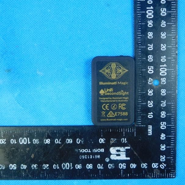
Click to zoom
Application Details
- Equipment Class
- DTS - Digital Transmission System
- Date of Grant
- Jun 05, 2023
- Application Purpose
- Original Equipment
- Date of Application
- Jun 01, 2023
- Equipment Note
- Unifi Second Sight
- Frequency Range
- 2402.00000000 - 2480.00000000
- Country
- Australia
Documents & Files
Document Text
Text extracted from the exhibit documents filed with the FCC. Open a document above to read the original.
Users Manual
© 2023 Allure Capital Pty Ltd ATFT Buzza Family Trust T/A Illuminati Magic Second Sight V2 Quick Reference Guide For Firmware 2.13 1 Contents Introduction ....................................................................................................................................... 2 Overview ............................................................................................................................................. 3 Button Operation ............................................................................................................................ 4 Charging Second Sight ................................................................................................................... 5 Vibrate Patterns ............................................................................................................................... 6 Wearing Second Sight .................................................................................................................... 7 Notifier Operation .......................................................................................................................... 8 Thumper Operation ........................................................................................................................ 9 Pairing Second Sight ..................................................................................................................... 10 Second Sight Settings ................................................................................................................... 11 Second Sight Vibrator Settings ................................................................................................ 16 RFID Deck ......................................................................................................................................... 22 Help and Support ........................................................................................................................... 24 Compliance ....................................................................................................................................... 25 FCC Caution ..................................................................................................................................... 26 2 Introduction Second Sight is an advanced RFID reader designed to enhance your magic performances. With a read range of up to 5 inches (125mm) and support for ISO14443A and ISO15693 protocols, Second Sight offers increased flexibility and compatibility with a wide range of RFID-tagged objects. With Second Sight, you have the freedom to position it in various locations, seamlessly integrating it into your routines. The onboard vibrator provides silent feedback, and by integrating with the Thumper, you can disable the onboard vibrator and rely solely on the Thumper's vibration signals. The intuitive button operations of Second Sight make it easy to access settings and modes for quick customization. Whether you need to adjust the vibration settings or switch between RFID protocols, Second Sight puts the control in your hands. Pairing Second Sight with the Unifi App unlocks a world of advanced features, customization options, and expanded capabilities. With the app, you can program RFID cards, customize display messages on the Notifier, and seamlessly integrate with other Unifi devices for a truly immersive magical experience. Unleash your creativity and captivate your audience with the power of Second Sight. Elevate your magic performances to new heights and create unforgettable moments with this versatile and powerful RFID reader. This is the Quick Reference Guide for Second Sight. For detailed video tutorials on Second Sight, refer to https://illuminati-magic.com/pages/second-sight-v2-training 3 Overview Object Description 1 Red Charging LED 2 Micro USB Charging Port 3 Power / Mode Selection Button 4 Status LED 1 2 3 4 4 Button Operation Button Description Long Press A long press on the power button is used to power Second Sight on or off. Press and hold the power button to turn it on, indicated by two vibrations and a white LED flash. To turn it off, press and hold the power button until you feel a single, long vibration and see a red LED flash. Single Tap A single tap on the power button exits the current mode or operation. Double Tap A double tap on the power button toggles the on board vibrate motor on or off. Two short vibrations indicate the vibrate motor is turned off, while a single, long vibration indicates it is turned on. Triple Tap A triple tap on the power button activates the Numeric Programming Mode. In this mode, you can program RFID/NFC tags with codes 1 through 13. The LED will flash red continuously and momentarily flash green when programming a tag. To exit this mode, a single tap on the power button is needed. Quadruple Tap A quadruple tap on the power button activates the Card Programming Mode. This mode allows you to program RFID/NFC tags with card values from Ace to King, in CHaSeD order (Clubs, Hearts, Spades, and Diamonds). The LED will flash red quickly and momentarily flash green when programming a tag. Quintuple Tap A quintuple tap on the power button in Second Sight changes the RFID/NFC Mode, toggling through ISO14443A, ISO15693, and Auto Mode. 5 Charging Second Sight Before using Second Sight, it is important to ensure that the device is properly charged. Begin by removing Second Sight from its packaging and locating the charging cable, which can be found underneath the plastic packaging. Connect one end of the cable to Second Sight and the other end to a wall-based USB charger. Once the cable is connected, a red charging LED will illuminate, indicating that the unit is charging. Allow Second Sight to charge until the red charging LED turns off, indicating that it is fully charged. The battery life of Second Sight can vary depending on the configuration options you have enabled in the setting…
Text truncated - open the document above for the full version.
Attestation Statements
Allure Capital Pty Ltd ATFT Buzza Family Trust T/A Illuminati Magic Covered Equipment Certification Attestation Letter 5/11/2023 Nemko North America, Inc. 303 River Road Ottawa K1V 1H2 Canada ATTN.: Reviewing Engineer FCC ID: 2A85X-SSV2 (Allure Capital Pty Ltd ATFT Buzza Family Trust T/A Illuminati Magic ) certifies that the equipment for which authorization is sought is not “covered” equipment prohibited from receiving an equipment authorization pursuant to section 2.903 of the FCC rules. Note: If the equipment for which the applicant seeks authorization is produced by any of the entities identified on the current Covered List, the applicant should include an explanation on why the equipment is not “covered” equipment. (Allure Capital Pty Ltd ATFT Buzza Family Trust T/A Illuminati Magic) certifies that, as of the date of the filing of the application, the applicant is not identified on the Covered List as an entity producing “covered” equipment. Signed: Printed name: Nathan Buzza Title: CEO Company Name: Allure Capital Pty Ltd ATFT Buzza Family Trust T/A Illuminati Magic Date: 5/11/2023
Cover Letter(s)
2023-05-11 Nemko Canada Inc 303 River Road Ottawa, Ontario, Canada K1V 1H2 Attn: Director of Certification Authority to Act as Agent On our behalf, I appoint Shenzhen Huatongwei International Inspection Co., Ltd./ 1/F, Bldg 3, Hongfa Hi-tech Industrial Park, Genyu Road, Tianliao, Gongming, Shenzhen, China / Hans Hu,. to act as our agent in the preparation of this application for equipment certification. I certify that submitted documents properly describe the device or system for which equipment certification is sought. I also certify that each unit manufactured, imported or marketed, as defined in the Federal Communications Commission’s regulations will have affixed to it a label identical to that submitted for approval with this application. For instances where our authorized agent signs the application for certification on our behalf, I acknowledge that all responsibility for complying with the terms and conditions for certification, as specified by Nemko Canada Inc, still resides with Allure Capital Pty Ltd ATFT Buzza Family Trust T/A Illuminati Magic / 19 Windarra Drive, City Beach WA 6015 AUSTRALIA Agency agreement expiration date: 2024-05-10 By: Nathan Buzza Signature Printed On behalf of : Allure Capital Pty Ltd ATFT Buzza Family Trust T/A Illuminati Magic Telephone: +61488862222
Cover Letter(s)
2023-05-11 Equipment Autorisation Division Federal Communications Commission 7435 Oakland Mills Road Columbia, MD 21046 FCC ID: 2A85X-SSV2 Product Name: Unifi Second Sight Request for Confidentiality Pursuant to Sections 0.457 and 0.459 of the commissions rules, we hereby request that the following documents be held confidential: Schematics Block diagram Operation description These materials contain trade secrets and proprietary information and are not customarily released to the public. The public disclosure of this information might be harmful to the company and provide unjustified benefits to our competitors. By: Nathan Buzza Signature Printed On behalf of : Allure Capital Pty Ltd ATFT Buzza Family Trust T/A Illuminati Magic Telephone: +61488862222
External Photos
External Photos of the EUT
Internal Photos
Internal Photos of the EUT
RF Exposure Info
FCC ID: 2A85X-SSV2 RF Exposure Evaluation REQUIREMENT KDB447498 D01 General RF Exposure Guidance v06, Clause 4.3.1(a) a) For 100 MHz to 6 GHz and test separation distances ≤ 50 mm, the 1-g and 10-g SAR test exclusion thresholds are determined by the following: [(max. power of channel, including tune-up tolerance, mW) / (min. test separation distance, mm)] · [√f(GHz)] ≤ 3.0 for 1-g SAR, and ≤ 7.5 for 10-g extremity SAR, where -f(GHz) is the RF channel transmit frequency in GHz -Power and distance are rounded to the nearest mW and mm before calculation -The result is rounded to one decimal place for comparison -The values 3.0 and 7.5 are referred to as numeric thresholds in step b) below The test exclusions are applicable only when the minimum test separation distance is ≤ 50 mm, and for transmission frequencies between 100 MHz and 6 GHz. When the minimum test separation distance is < 5 mm, a distance of 5 mm according to 4.1 f) is applied to determine SAR test exclusion. b) For 100 MHz to 6 GHz and test separation distances > 50 mm, the 1-g and 10-g SAR test exclusion thresholds are determined by the following (also illustrated in Appendix B): 1) {[Power allowed at numeric threshold for 50 mm in step a)] + [(test separation distance – 50 mm)·(f(MHz)/150)]} mW, for 100 MHz to 1500 MHz 2) {[Power allowed at numeric threshold for 50 mm in step a)] + [(test separation distance – 50 mm)·10]} mW, for > 1500 MHz and ≤ 6 GHz c) For frequencies below 100 MHz, the following may be considered for SAR test exclusion (also illustrated in Appendix C): 1) For test separation distances > 50 mm and < 200 mm, the power threshold at the corresponding test separation distance at 100 MHz in step b) is multiplied by [1 + log(100/f(MHz))] 2) For test separation distances ≤ 50 mm, the power threshold determined by the equation in c) 1) for 50 mm and 100 MHz is multiplied by ½ 3) SAR measurement procedures are not established below 100 MHz. When SAR test exclusion cannot be applied, a KDB inquiry is required to determine SAR evaluation requirements for any SAR test results below 100 MHz to be acceptable. For simultaneous transmission SAR test exclusion considerations: KDB447498 D01 General RF Exposure Guidance v06, Clause 4.3.2(b ) KDB447498 D01 General RF Exposure Guidance v06, Clause 4.3.2(c): When the sum of SAR is larger than the limit, SAR test exclusion is determined by the SAR to peak location FCC ID: 2A85X-SSV2 separation ratio. The simultaneously transmitting antennas in each operating mode and exposure condition combination must be considered one pair at a time to determine the SAR to peak location separation ratio to qualify for test exclusion. The ratio is determined by (SAR1 + SAR2) 1.5 /Ri, rounded to two decimal digits, and must be ≤ 0.04 for all antenna pairs in the configuration to qualify for 1-g SAR test exclusion. When 10-g SAR applies, the ratio must be ≤ 0.10. SAR1 and SAR2 are the highest reported or estimated SAR values for each antenna in the pair, and Ri is the separation distance in mm between the peak SAR locations for the antenna pair. TEST RESULT Passed Not Applicable Radio Type Frequency range (MHz) Conducted Power (dBm) Maximum Tune-up (dBm) Calculating data Limit Result Bluetooth 2402-2480 0.17 0.32 0.3268 3.00 Pass Note: 1) The maximum antenna gain is 0.2dBi 2) The exposure evaluation safety distance is 5mm. Test Frequency H-field strength (dBuV/m) H-field strength (dBm) H-field strength (mW) Limit (mW) Result 433.92MHz 81.16 -14.04 0.04 3.0 Pass Note: 1) The 433.92MHz maximum antenna gain is -9.8dBi 2) The exposure evaluation safety distance is 5mm. 3) (dBm)=E(dBuV/m)+20log(d)-104.77=E(dBuV/m)-95.2 Test Frequency H-field strength (dBuV/m) H-field strength (dBm) H-field strength (mW) Limit (mW) Result 13.56MHz 59.86 -35.34 0.000292 443 Pass Note: 1) The exposure evaluation safety distance is 5mm 2) (dBm)=E(dBuV/m)+20log(d)-104.77=E(dBuV/m)-95.2 FCC ID: 2A85X-SSV2 For the device transmitting simultaneously conditions, according to KDB447498 D01 General RF Exposure Guidance v06 section 4.3.2 (b), Radio Type Frequency range (MHz) Conducted Power (dBm) Maximum Tune-up (dBm) Calculating data (W/kg) Limit(W/kg) Result Bluetooth 2402-2480 0.17 0.32 0.0452 0.4 Pass Note: 1) The maximum antenna gain is 0.2dBi 2) The exposure evaluation safety distance is 5mm. Test Frequency H-field strength (dBuV/m) H-field strength (dBm) Calculating data (W/kg) Limit (W/kg) Result 433.92MHz 81.16 -14.04 0.0007 0.4 Pass Note: 1) The 433.92MHz maximum antenna gain is -9.8dBi 2) The exposure evaluation safety distance is 5mm. 3) (dBm)=E(dBuV/m)+20log(d)-104.77=E(dBuV/m)-95.2 Test Frequency H-field strength (dBuV/m) H-field strength (dBm) Calculating data (W/kg) Limit (W/kg) Result 13.56MHz 59.86 -35.34 0.0001 0.4 Pass Note: 1) The exposure evaluation safety distance is 5mm 2) (dBm)=E(dBuV/m)+20log(d)-104.77=E(dBuV/m)-95.2 So, Bluetooth + 433.92MHz + 13.56MHz=0.0452+0.0007+0.0001=0.046 ≤0.4 W/kg,it can be exempted the SAR testing
Test Report
Page: 1 of 33 TEST REPORT For Bluetooth-LE Report No. ...................................... : CHTEW23020025 Report Verification: Project No.................................: SHT2209083917EW FCC ID ............................................. : 2A85X-SSV2 Applicant’s name ........................... : Allure Capital Pty Ltd ATFT Buzza Family Trust T/A Illuminati Magic Address ............................................. : 19 Windarra Drive, City Beach WA 6015 AUSTRALIA Product Name ................................ : Unifi Second Sight Trade Mark ....................................... : - Model No. ......................................... : Second Sight V2 Listed Model(s) ................................. : - Standard ......................................... : FCC CFR Title 47 Part 15 Subpart C Section 15.247 Date of receipt of test sample..........: Oct.21, 2022 Date of testing.............................: Oct.22, 2022-Feb.03, 2023 Date of issue...............................: Feb.06, 2023 Result .................. ........................: PASS Compiled by ( position+printedname+signature) ... : File administrators Fanghui Zhu Supervised by (position+printedname+signature) .... : Project Engineer Kiki Kong Approved by (Position+Printed name+Signature): RF Manager Hans Hu Testing Laboratory Name ............. : Shenzhen Huatongwei International Inspection Co., Ltd. Address ............................................. : 1/F, Bldg 3, Hongfa Hi-tech Industrial Park, Genyu Road, Tianliao, Gongming, Shenzhen, China Shenzhen Huatongwei International Inspection Co., Ltd. All rights reserved. This publication may be reproduced in whole or in part for non-commercial purposes as long as the Shenzhen Huatongwei International Inspection Co., Ltd. is acknowledged as copyright owner and source of the material. Shenzhen Huatongwei International Inspection Co., Ltd. takes no responsibility for and will not assume liability for damages resulting from the reader's interpretation of the reproduced material due to its placement and context. The test report merely correspond to the test sample. Report No.: CHTEW23020025 Page: 2 of 33 Date of issue: 2023-02-06 Shenzhen Huatongwei International Inspection Co., Ltd. Report Template Version: V04 (2022-01) Contents 1. TEST S T AN D AR D S A N D R E P O R T V E R S I O N 3 1.1. Test Standards 3 1.2. Report version 3 2. TEST DESCRIPTION 4 3. SUMMARY 5 3.1. Client Information 5 3.2. Product Description 5 3.3. Radio Specification Description 5 3.4. Testing Laboratory Information 6 4. TEST CONFIGURATION 7 4.1. Test frequency list 7 4.2. Descriptions of Test mode 7 4.3. Test sample information 7 4.4. Support unit used in test configuration and system 8 4.5. Testing environmental condition 8 4.6. Statement of the measurement uncertainty 8 4.7. Equipment Used during the Test 9 5. TEST CONDITIONS AND RESULTS 11 5.1. Antenna Requirement 11 5.2. AC Conducted Emission 12 5.3. Peak Output Power 14 5.4. Power Spectral Density 15 5.5. 6dB bandwidth 16 5.6. 99% Occupied Bandwidth 17 5.7. Duty Cycle 18 5.8. Conducted Band edge and Spurious Emission 19 5.9. Radiated Band edge Emission 20 5.10. Radiated Spurious Emission 22 6. TEST SETUP PHOTOS 27 7. EXTERNAL AND INTERNAL PHOTOS 29 8. APPENDIX REPORT 33 Report No.: CHTEW23020025 Page: 3 of 33 Date of issue: 2023-02-06 Shenzhen Huatongwei International Inspection Co., Ltd. Report Template Version: V04 (2022-01) 1. TEST STAND ARDS AND REPORT VERSION 1.1. Test Standards The tests were performed according to following standards: ‒ FCC Rules Part 15.247: Frequency Hopping, Direct Spread Spectrum and Hybrid Systems that are in operation within the bands of 902-928 MHz, 2400-2483.5 MHz, and 5725-5850 MHz ‒ ANSI C63.10:2013: American National Standard for Testing Unlicensed Wireless Devices ‒ KDB 558074 D01 15.247 Meas Guidance v05r02: Guidance for Compliance Measurements on Digital Transmission System, Frequency Hopping Spread Spectrum System, and Hybrid System Devices Operating under Section 15.247 of The FCC Rules 1.2. Report version Revision No. Date of issue Description N/A 2023-02-06 Original Report No.: CHTEW23020025 Page: 4 of 33 Date of issue: 2023-02-06 Shenzhen Huatongwei International Inspection Co., Ltd. Report Template Version: V04 (2022-01) 2. TEST DESCRIPTION Report clause Test Items Standard Requirement Result Test Engineer 5.1 Antenna Requirement 15.203/15.247(c) PASS Xiaoxiao Li 5.2 AC Conducted Emission 15.207 PASS Junman Wang 5.3 Peak Output Power 15.247(b)(3) PASS Xiaoxiao Li 5.4 Power Spectral Density 15.247(e) PASS Xiaoxiao Li 5.5 6dB Bandwidth 15.247(a)(2) PASS Xiaoxiao Li 5.6 99% Occupied Bandwidth - PASS *1 Xiaoxiao Li 5.7 Duty cycle - PASS *1 Xiaoxiao Li 5.8 Conducted Band Edge and Spurious Emission 15.247(d)/15.205 PASS Xiaoxiao Li 5.9 Radiated Band Edge Emission 15.205/15.209 PASS Yifan Wang 5.10 Radiated Spurious Emission 15.247(d)/15.205/15.209 PASS Chuanfeng Li Note: ‒ The measurement uncertainty is not included in the test result. ‒ *1: No requirement on standard, only report these test data. Report No.: CHTEW23020025 Page: 5 of 33 Date of issue: 2023-02-06 Shenzhen Huatongwei International Inspection Co., Ltd. Report Template Version: V04 (2022-01) 3. SUMMARY 3.1. Client Information Applicant: Allure Capital Pty Ltd ATFT Buzza Family Trust T/A Illuminati Magic Address: 19 Windarra Drive, City Beach WA 6015 AUSTRALIA Manufacturer: Allure Capital Pty Ltd ATFT Buzza Family Trust T/A Illuminati Magic Address: 19 Windarra Drive, City Beach WA 6015 AUSTRALIA Fatory: Rigao Electronics Limited Address: Rm411 E/Bld MingXi Creative Park Huaide Community Fuyong Sub-dist Bao'An Dist SZ 518128 China 3.2. Product Description Main unit information: Product Name: Unifi Second Sight Trade Mark: - Model No.: Second Sight V2 Listed Model(s): - Power supply: DC 3.7V from Battery Hardware version: 1.0 Software version: 2.10 Accessory unit information: Battery information: 3.7V 250mAh 3.3. Radio Specification Descriptio…
Text truncated - open the document above for the full version.
Test Report
Project No.: SHT2209083917EW Radio Specification: Bluetooth BLE Shenzhen Huatongwei International Inspection Co., Ltd. Appendix report page: 1 of 14 APPENDIX REPORT Project No. SHT2209083917EW Radio Specification Bluetooth BLE Test sample No. YPHT22090839033 Model No. Second Sight V2 Start test date 2022-12-05 Finish date 2022-12-06 Temperature 24.8 Humidity 35% Test Engineer Xiaoxiao Li Auditor Appendix clause Test item Result A Peak Output Power PASS B Power Spectral Density PASS C 6 dB Bandwidth PASS D 99% Occupied Bandwidth PASS E Duty cycle PASS F Band edge and Spurious Emissions (conducted) PASS Project No.: SHT2209083917EW Radio Specification: Bluetooth BLE Shenzhen Huatongwei International Inspection Co., Ltd. Appendix report page: 2 of 14 Appendix A:Peak Output Power Type Channel Peak Output power (dBm) Average Output power (dBm) Limit (dBm) Result BT-BLE 00 0.21 0.17 ≤ 30.00 Pass 19 0.06 0.05 39 -0.69 -0.71 Project No.: SHT2209083917EW Radio Specification: Bluetooth BLE Shenzhen Huatongwei International Inspection Co., Ltd. Appendix report page: 3 of 14 CH00 Date: 5.DEC.2022 08:34:41 CH19 Date: 5.DEC.2022 08:44:16 CH39 Date: 5.DEC.2022 08:41:43 Project No.: SHT2209083917EW Radio Specification: Bluetooth BLE Shenzhen Huatongwei International Inspection Co., Ltd. Appendix report page: 4 of 14 Appendix B:Power Spectral Density Type Channel Power Spectral Density(dBm/3KHz) Limit (dBm/3KHz) Result BT-BLE 00 -9.61 ≤8.00 Pass 19 -9.63 39 -10.90 Project No.: SHT2209083917EW Radio Specification: Bluetooth BLE Shenzhen Huatongwei International Inspection Co., Ltd. Appendix report page: 5 of 14 CH00 Date: 5.DEC.2022 08:37:48 CH19 Date: 6.DEC.2022 09:04:19 CH39 Date: 6.DEC.2022 09:06:19 Project No.: SHT2209083917EW Radio Specification: Bluetooth BLE Shenzhen Huatongwei International Inspection Co., Ltd. Appendix report page: 6 of 14 Appendix C:6dB bandwidth Type Channel 6dB Bandwidth(kHz) Limit (kHz) Result BT-BLE 00 772.00 ≥500 Pass 19 788.00 39 806.00 Project No.: SHT2209083917EW Radio Specification: Bluetooth BLE Shenzhen Huatongwei International Inspection Co., Ltd. Appendix report page: 7 of 14 CH00 Date: 5.DEC.2022 08:34:20 CH19 Date: 6.DEC.2022 09:03:56 CH39 Date: 6.DEC.2022 09:05:56 Project No.: SHT2209083917EW Radio Specification: Bluetooth BLE Shenzhen Huatongwei International Inspection Co., Ltd. Appendix report page: 8 of 14 Appendix D:99% Occupied Bandwidth Type Channel 99% Occupied Bandwidth(MHz) Limit (kHz) Result BT-BLE 00 1.04 - Pass 19 1.06 39 1.06 Project No.: SHT2209083917EW Radio Specification: Bluetooth BLE Shenzhen Huatongwei International Inspection Co., Ltd. Appendix report page: 9 of 14 CH00 Date: 5.DEC.2022 08:34:32 CH19 Date: 6.DEC.2022 09:04:04 CH39 Date: 6.DEC.2022 09:06:04 Project No.: SHT2209083917EW Radio Specification: Bluetooth BLE Shenzhen Huatongwei International Inspection Co., Ltd. Appendix report page: 10 of 14 Appendix E:Duty cycle Test Frequency (MHz) T on time for single burst (ms) T period (ms) Duty cycle 1/T on time (kHz) 2442 1.00 1.00 100% 1 Project No.: SHT2209083917EW Radio Specification: Bluetooth BLE Shenzhen Huatongwei International Inspection Co., Ltd. Appendix report page: 11 of 14 Appendix F:Band edge and Spurious Emissions (conducted) Test Item: Band edge CH00 Date: 5.DEC.2022 08:37:58 CH39 Date: 6.DEC.2022 09:06:29 Project No.: SHT2209083917EW Radio Specification: Bluetooth BLE Shenzhen Huatongwei International Inspection Co., Ltd. Appendix report page: 12 of 14 Test Item: SE CH00 Reference level Date: 5.DEC.2022 08:38:07 CH00 30MHz~1000MHz Date: 5.DEC.2022 08:38:22 CH00 1GHz~26GHz Date: 5.DEC.2022 08:38:39 Project No.: SHT2209083917EW Radio Specification: Bluetooth BLE Shenzhen Huatongwei International Inspection Co., Ltd. Appendix report page: 13 of 14 CH19 Reference level Date: 6.DEC.2022 09:04:57 CH19 30MHz~1000MHz Date: 6.DEC.2022 09:05:13 CH19 1GHz~26GHz Date: 6.DEC.2022 09:05:29 Project No.: SHT2209083917EW Radio Specification: Bluetooth BLE Shenzhen Huatongwei International Inspection Co., Ltd. Appendix report page: 14 of 14 CH39 Reference level Date: 6.DEC.2022 09:06:36 CH39 30MHz~1000MHz Date: 6.DEC.2022 09:06:51 CH39 1GHz~26GHz Date: 6.DEC.2022 09:07:08 --------End of Report--------
Test Report
Micro Reach Xtend TM (NN01- 110) – Bluetooth®, Zigbee®, 802.11 b/g/n WLAN USER MANUAL Micro Reach Xtend TM (NN01-110) 2 Last Update: June 2021 USER MANUAL Micro Reach Xtend TM (NN01-110) Micro Reach Xtend TM (NN01-110) – Bluetooth®, Zigbee®, 802.11 b/g/n WLAN Ignion specializes in enabling effective mobile communications. Using Ignion technology, we design and manufacture optimized antennas to make your wireless devices more competitive. Our mission is to help our clients develop innovative products and accelerate their time to market through our expertise in antenna design, testing and manufacturing. Micro Reach Xtend TM NN01-110 Ignion products are protected by Ignion patents. All information contained within this document is property of Ignion and is subject to change without prior notice. Information is provided “as is” and without warranties. It is prohibited to copy or reproduce this information without prior approval. Ignion is an ISO 9001:2015 certified company. All our antennas are lead-free and RoHS compliant. ISO 9001: 2015 Certified 3 Last Update: June 2021 USER MANUAL Micro Reach Xtend TM (NN01-110) INDEX OF CHAPTERS 1. ANTENNA DESCRIPTION 5 2. QUICK REFERENCE GUIDE 6 3. ELECTRICAL PERFORMANCE 6 4. MECHANICAL CHARACTERISTICS 11 5. ASSEMBLY PROCESS 12 6. PACKAGING 14 7. PRODUCT CHANGE NOTIFICATION 16 4 Last Update: June 2021 USER MANUAL Micro Reach Xtend TM (NN01-110) TABLE OF CONTENTS 1. ANTENNA DESCRIPTION 5 2. QUICK REFERENCE GUIDE 6 3. ELECTRICAL PERFORMANCE 6 3.1. EVALUATION BOARD 6 3.2. MATCHING NETWORK 7 3.3. VSWR AND EFFICIENCY 8 3.4. RADIATION PATTERNS (2.4 – 2.5 GHz), GAIN AND EFFICIENCY 9 3.5. CAPABILITIES AND MEASUREMENT SYSTEMS 10 4. MECHANICAL CHARACTERISTICS 11 4.1. DIMENSIONS AND TOLERANCES 11 4.2. SPECIFICATIONS FOR THE INK 11 4.3. ANTENNA FOOTPRINT 12 5. ASSEMBLY PROCESS 12 6. PACKAGING 14 7. PRODUCT CHANGE NOTIFICATION 16 5 Last Update: June 2021 USER MANUAL Micro Reach Xtend TM (NN01-110) 1. ANTENNA DESCRIPTION The Micro Reach Xtend TM chip antenna is a very small size and low cost antenna that combines reduced clearance area required within the customer PCB with its high performance and integration flexibility. This makes it ideal for small consumer electronics devices such as small wireless headsets and highly integrated multifunction mobile handsets. TOP BOTTOM Material: The Micro Reach Xtend TM antenna is built on glass epoxy substrate. APPLICATIONS • Headsets • Hearing-aids • USB Dongles • Medical devices • Handsets • Sensors (Proximity, etc.) BENEFITS • Small form factor and footprint • Reduced clearance area within PCB • Cost-effective • Easy to integrate (pick and place) 2. QUICK REFERENCE GUIDE Technical Features 2.4 – 2.5 GHz Average Efficiency > 55% Peak Gain 0.2 dBi VSWR < 2.5:1 Radiation Pattern Omnidirectional Polarization Linear Weight (approx.) 0.02 g Temperature -40 to +125º C Impedance 50 Ω Dimensions (L x W x H) 4.1 mm x 2.0 mm x 1.0 mm Table 1 – Technical Features. Measures from the evaluation board. See Figure 1. Please contact [email protected] if you require additional information on antenna integration or optimization on your PCB. 1.0 mm 2 .0 mm 4 .1 mm 6 Last Update: June 2021 USER MANUAL Micro Reach Xtend TM (NN01-110) 3. ELECTRICAL PERFORMANCE 3.1. EVALUATION BOARD The configuration used in testing the Micro Reach Xtend TM chip antenna is displayed in Figure 1. Measure mm A 35.0 B 20.0 C 40.0 D 5.2 E 20.0 F 12.5 G 7.0 H 5.0 Tolerance: ±0.2mm Material: The evaluation board is built on FR4 substrate. Thickness is 1.0mm. Clearance Area: 7.0 mm x 5.0 mm (GxH) Figure 1 – EB_NN01-110. Micro Reach Xtend TM Evaluation Board providing operation from 2.4 GHz to 2.5GHz. This product and/or its use are protected by at least one or more of the following patents US 7,148,850 B2; US 7,202,822 B2. 7 Last Update: June 2021 USER MANUAL Micro Reach Xtend TM (NN01-110) 3.2. MATCHING NETWORK The specs of a Ignion standard antenna are measured in their evaluation board, which is an ideal case. In a real design, components nearby the antenna, LCD’s, batteries, covers, connectors, etc affect the antenna performance. This is the reason why it is highly recommended placing pads compatible with 0402 and 0603 SMD components for a PI matching network as close as possible to the antenna feeding point. Do it in the ground plane area, not in the clearance area. This is a degree of freedom to tune the antenna once the design is finished and taking into account all elements of the system (batteries, displays, covers, etc). Please notice that different devices with different ground planes and different components nearby the Micro Reach Xtend™ chip antenna may need a different matching network. To ensure optimal results, the use of high Q and tight tolerance components is highly recommended (Murata components). If you need assistance to design your matching network beyond this application note, please contact [email protected], or try our free-of-charge 1 NN Wireless Fast- Track design service, you will get your chip antenna design including a custom matching network for your device in 24h 1 . Other related to NN’s range of R&D services is available at: https://www.ignion.io/rdservices/ Matching Network for the Evaluation Board Value Part Number 6.1 nH LQW15AN6N1B80 1.5 pF GJM1555C1H1R5WB01 Figure 2 – Matching network implemented in the evaluation board (Figure 1). 1 See terms and conditions for a free NN Wireless Fast-Track service in 24h at: https://www.ignion.io/fast-track-project/ 8 Last Update: June 2021 USER…
Text truncated - open the document above for the full version.
Contact Information
Applicant
Nathan E Buzza(CEO)
Test Firm
Shenzhen Huatongwei International Inspection Co.,Tony Jiang
[email protected]+86-755-26748078
Technical Specifications
| # | Rule Parts | Frequency Range | Power Output |
|---|---|---|---|
| 1 | 15C | 2.40 GHz - 2.48 GHz | 1.05 mW |