2A87F-CIRCAZG CHAIR
DONGGUAN CASTLE MARK FURNITURE CO., LTD.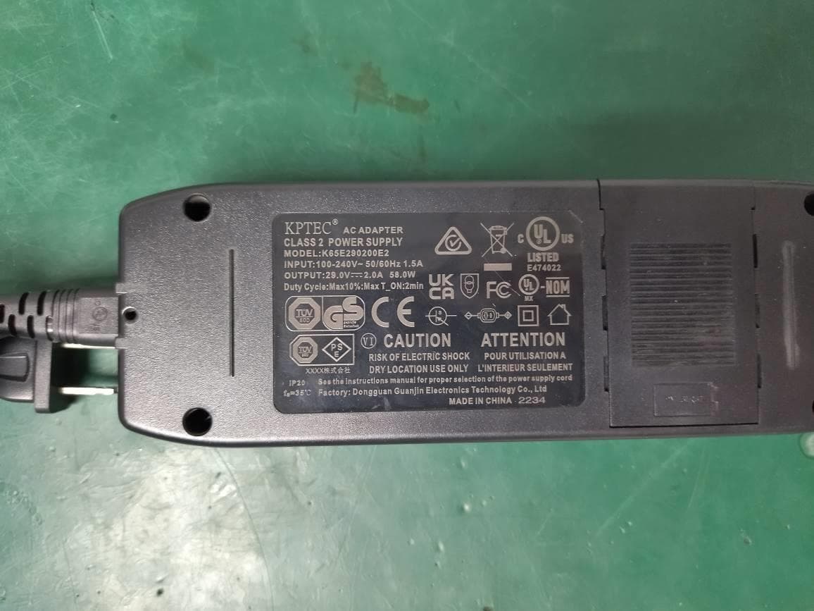
Click to zoom
Application Details
- Equipment Class
- DTS - Digital Transmission System
- Date of Grant
- Apr 26, 2023
- Application Purpose
- Original Equipment
- Date of Application
- Mar 27, 2023
- Equipment Note
- ZG CHAIR
- Frequency Range
- 2402.00000000 - 2480.00000000
- Country
- China
Documents & Files
Document Text
Text extracted from the exhibit documents filed with the FCC. Open a document above to read the original.
Users Manual
• Never use pins or other metallic fasteners with this appliance. • Carefully examine the covering before each use. Discard the appliance if the covering shows any sign of deterioration, such as checking, blistering, or cracking. • Keep Dry-Do not operate in a wet or moist condition. • Use heated surfaces carefully. May cause serious burns. Do not use over insensitive skin areas or in the presence of poor circulation. The unattended use of heat by children or incapacitated persons may be dangerous. This equipment has been tested and found to comply with the limits for a Class B digital device, pursuant to part 15 of the FCC Rules. These limits are designed to provide reasonable protection against harmful interference in a residential installation. This equipment generates, uses and can radiate radio frequency energy and, if not installed and used in accordance with the instructions, may cause harmful interference to radio communications. However, there is no guarantee that interference will not occur in a particular installation. If this equipment does cause harmful interference to radio or television reception, which can be determined by turning the equipment off and on, the user is encouraged to try to correct the interference by one or more of the following measures: —Reorient or relocate the receiving antenna. —Increase the separation between the equipment and receiver. —Connect the equipment into an outlet on a circuit different from that to which the receiver is connected. —Consult the dealer or an experienced radio/ TV technician for help. FCC Radiation Exposure Statement: This equipment complies with FCC radiation exposure limits set forth for an uncontrolled environment. In order to avoid the possibility of exceeding the FCC radio frequency exposure limits, Human proximity to the antenna shall not be less than 20cm (8 inches) during normal operation. To reduce the risk of electric shock, this appliance has a polarized plug (one blade is wider than the other). This plug will fit in a polarized outlet only one way. If the plug does not fit fully in the outlet, reverse the plug. If it still does not fit, contact a qualified electrician to install the proper outlet. Do not change the plug in any way. 37 W, DC 29V, 1.2A 66” L x 32.5” W x 25.5” H 135.6 Lbs 28” 330 Lbs grounding instructions specifications get ready Pillow Arm Rest Foot Rest Seat Rest Back Rest Remote Control USB Rating: DC 5-12V, Max 3.4A take control 1 2 6 7 8 10 9 4 3 5 4. Stretch Press the stretch button to activate a slightly harder massage that gives special attention to your spine by slowly stretching it at different points and releasing stress. 1. Smart nap Press the optional 15min/30min/60min timer button to start smart nap mode. When time is up, the On/Off button will flash, soft air massage will begin, and the chair will bring the user back to the home position. 2. ZeroG On pressing the ZGR button, the back rest, foot rest, and seat will be automatically adjusted to preset reclining angles. The reclining motion can be stopped by pressing either the ZGR button, the back rest recline/restore button, or the foot rest raise/restore button. After achieving the ZGR position, you may still adjust the angles of the back rest and foot rest by pressing the relevant buttons. 3. On/Off Button On pressing the On/Off button, a light will tell you that the chair is in the idle functioning mode and will commence a massage program when you press any other function button. If during a massage function program, should you wish to suspend for any reason, please press the On/Off button and the program will cease. 5. Relax Press this button to activate an air massage program. It is a wonderful all round air massage for gentle relaxation and loosening of muscles. Note: With the air massage in action, should you wish to change the angle of the back or foot rest, the program will pause and resume automatically once the back or foot rest movement is completed. 6. Heat Press this button to commence the heating function for the lumbar and seat region. A light will indicate that the heating function is in operation. Press the button again to cease the function. With the heating function in operation, should you wish to change the angle of the back rest or foot rest, the heating function will pause and resume automatically once the back rest or foot rest movement is completed. Foot Rest - Restore Press and hold this button until the foot is at your desired angle. Movement will be stopped once you let go of the button. Back Rest & Foot Rest - Restore Press and hold this button until the back and foot is at your desired angle. Movement will be stopped once you let go of the button. Back Rest & Foot Rest - Raise Press and hold this button until the back and foot is at your desired angle. Movement will be stopped once you let go of the button. Note: 1. When you press and hold two buttons at the same time for more than 5 seconds, you can disable the functions of the all buttons. Or you can use the same operation to restore the functions of the all buttons 2.When activating the foot rest, the chair will not simultaneously respond to the heat and air massage functions. Foot Rest- Raise Press and hold this button until the foot is at your desired angle. Movement will be stopped once you let go of the button. Note: When activating the foot rest, the chair will not simultaneously respond to the back rest restore/raise action, heat, and air massage functions. 7. I & II Press and hold the I or II for 2 seconds to create a new memory position. 8. Lumbar Press the lumbar button to start a 15 second airbag inflation, press again to hold the current lumbar inflation position, press a third time to deflate the lumbar airbag. Lumbar support will stop working if you press the air massage button, and vice versa. Lumbar support will hold even when the chair turns off, press again or power the chair off to deflate. It takes 25 seconds for full airbag deflatio…
Text truncated - open the document above for the full version.
Cover Letter(s)
WLT8266BM antenna Small Size 2.4 GHz PCB antenna 1 INTRODUCTION and considerations for complying with regulatory limits when using this design. The suggested antenna design requires no more than 1 3.2 x 4.6 mm of space and ensures a VSWR ratio of less than 2 across the 2.4 GHz ISM band when connected to a 50 ohm source. The PCB antenna used on the WLT8266BM reference design is described in this application note. Even if the antenna presented is for a W LT8266BM it can be used in all 2.4 GHz designs, especially where small space is required for the antenna. This application note describes the antenna dimensions, the RF performance Manufacturer Company NameDongguan Xuancai Optoelectronics Technology Co., Ltd. Company AddressNo. 2 Gem Road, Jiaoyitang Town, Tangxia Town, moved to the 2nd floor, Unit 1, Building 1, Science and Technology Innovation Park. 。 · 34 5 • , s · 210· 165" 180' Vertical Polarization m B AU ,‘ ”... M JP 剧升...阴阳川机 M ιm U E- AU M EF C4 R usbXY Figure 7: WLT8266BM XV Plane ”。risontalPolar泣.ation usbXY 。 - ’”. tfi6• ” : O" Figure 8: WLT8266BM XV Plane CF 2450.000”Hz 5 dBi div Ref Lev:纪.�.... dB 国F 1 5 ' 手4 5 • ” · . 川、 Ji l -- 1 ‘ γ飞、 ιiilift 270' CF 2450.000 MHz 4dBI div 'l.. 2.. Ref Lev:“........... dBm 1 00 · 飞回5' v,而臼lPo陆r国筒。” Figure 9: WLT8266BM XZ Plane usbXZ 270' ”。而sontal Pola同zatlon XZ 345 ' ’ s · 1串串· Figure 10: WLT8266BM XZ Plane CF 24朋.”。”地 4dBI div Ref Lev:“三主...dBm 34 S ' I S ' 270' 1so· 蜘 l · 刷 几 ... mρ...仰川WF创dc2R Ve rtical Polarization Y Z Figure 11: WLT8266BM VZ Plane Hot施。ntalPolarization YZ 34 5 ' 1 5 ' 唯 65 ' 180' Figure 12:WLT8266BM VZ Plane CF :USO.。””“z 3dB/div 90 ')' -1, '2.. Ref L例:....·......dBm , 345 ' 1 s · 210• 9 0 • 1 80 ' m e h J M J ... 阳 斗 ... 4d 制 2 剧团 l Fd 创 FUR-- En Verti臼l Po阳市刷on Laptop xv Figure 13: WLT8266BM XV Plane 白 ’ 345 • 270户 ’ 80 ' ”。时,ontal Polarizati。” L aptop xv 15' CF 2450.例如OMt也 4 dB/ div 窜。- Ref Lev: .2.立...dBm Figure 14: WLT8266BM XV Plane 4 CONCLUSION This application note shows that it is possible to implement a 2.4 GHz antenna on a small area and still achieve good performance. Table 6 lists the most important properties of the Inverted F Antenna, described in this document. The free line of sight (LOS) range was measured with 250 kbps and 1 % PER. Gain in×Yolane 4.5 dB Gain in×Z olane 5.3 dB Gain in YZ olane 5.3 dB Gain in×Yolane, connected to laotoo 3.3 dB LOS ranae 240m Antenna size 13 .2x 4.6 mm
Cover Letter(s)
DONGGUAN CASTLE MARK FURNITURE CO., LTD. Confidentiality Letter Date: 2023-01-10 Subject: Confidentiality Request for FCC ID: 2A87F-CIRCA Pursuant to FCC 47 CRF 0.457(d) and 0.459, the applicant requests that a part of the subject FCC application be held confidential. Type of Confidentiality Requested Exhibit Short Term Permanent Block Diagrams Short Term Permanent Internal Photos *** Short Term Permanent Operation Description/Theory of Operation Short Term Permanent Antenna datasheet Short Term Permanent Schematics Short Term Permanent User’s Manual*** Short Term n/a Test Setup Short Term n/a External Photos DONGGUAN CASTLE MARK FURNITURE CO., LTD. has spent substantial effort in developing this product and it is one of the first of its kind in industry. Having the subject information easily available to "competition" would negate the advantage they have achieved by developing this product. Not protecting the details of the design will result in financial hardship. Permanent Confidentiality: The applicant requests the exhibits listed above as permanently confidential be permanently withheld from public review due to materials that contain trade secrets and proprietary information not customarily released to the public. Short-Term Confidentiality: The applicant requests the exhibits selected above as short term confidential be with held from public view for a period of 180 days from the date of the Grant of Equipment Authorization and prior to marketing. This is to avoid premature release of sensitive information prior to marketing or release of the product to the public. Applicant is also aware that they are responsible to notify TUV Rheinland in the event information regarding the product or the product is made available to the public. TUV Rheinland will then release the documents listed above for public disclosure pursuant to FCC Public Notice DA 04- 1705. Sincerely, By: TITI.YU (Signature/ Manager) (Print name)
Internal Photos
RF ANT
Parts List/Tune Up Info
WLT8266BM antenna Small Size 2.4 GHz PCB antenna 1 INTRODUCTION and considerations for complying with regulatory limits when using this design. The suggested antenna design requires no more than 1 3.2 x 4.6 mm of space and ensures a VSWR ratio of less than 2 across the 2.4 GHz ISM band when connected to a 50 ohm source. The PCB antenna used on the WLT8266BM reference design is described in this application note. Even if the antenna presented is for a W LT8266BM it can be used in all 2.4 GHz designs, especially where small space is required for the antenna. This application note describes the antenna dimensions, the RF performance Manufacturer Company NameDongguan Xuancai Optoelectronics Technology Co., Ltd. Company AddressNo. 2 Gem Road, Jiaoyitang Town, Tangxia Town, moved to the 2nd floor, Unit 1, Building 1, Science and Technology Innovation Park. ANTENNA DESIGN The PCB antenna on the WLT8266BM reference design is a meande「ed Inverted F Antenna (IFA). The IFA was designed to match an impedance of 50 ohm at 2.45 GHz. Thus no additional matching components are necessary. 2 Design Goals The reflection at the feed point of the antenna determines how much of the applied power is d elivered to the antenna. A reflection of less than -10 dB across the 2.4 GHz ISM band, when connected to a 50 ohm source, was a design goal. Reflection of less than斗O dB, or VSWR less than 2, ensures that more than 90% of the available power is delivered to the antenna. Bandwidth is in this d ocument defined as the f「equency band where mo「e than 90% of the available power is delivered to the antenna. Another design goal was to fit the size of the PCB antenna on a WLT8266BM and to obtain good pe时ormance also when the dongle is connected to a computer. 2.1 Simulation IE3D from Zeland, which is an electromagnetic simulation tool, was used to design the antenna. The accuracy of the simulation is controlled by the mesh. An increase of the mesh increases the simulation time. Thus, for initial simulations mesh = 1 should be used. When a fairly good result is achieved a higher mesh should be used to obtain more accurate results. Comparison of simulation and measurement results shows that the measured reflection is between the result obtained with mesh = 5 and mesh = 1 ; see Figure 2 for details. 2.2 -3 - 12 也 飞, - 21 -2 7 - 1 5 · 1 8 - 9 ...• Simulated mesh6 -Simulated mesh1 一 ···· ·&T o --, .... ,,,, ........ 01· …- Measured free s p ,oe 3 , ·24 · 。 -3 “ 6 - 9 - 1 2 国 飞, · 1 5 - 1 8 -2 7 - 21 -30 3 28 2 7 24 25 26 Froqu•ncy (GHz) 23 22 2. - 30 2 Figure 2: C。mparisonof Simulation and Measurements Results 2.3 Layout and Implementation Small changes of the antenna dimensions may have large impact on the performance. Therefore it is strongly recommended to make an exact copy of the reference design to achieve optimum pe斤。rmance. The easiest way to implement the antenna is to import the gerber or DXF file showing the antenna layout. The imported file can be used as a template when drawing the antenna. By using this procedure it should be possible to make an exact copy. If the PCB CAD tool being used does not suppo叫impo时of DXF or gerber files, Figu「e 3 and Table 1 should be used to ensure correct implementation. It is recommended to gene「ate a gerber fi le for compa「isοn with IFA_USB.spl when making a manual implementation. Most g erber viewers have the possibility to impo同several gerbe「 files at the same time. Thus by placing the gerber file, showing the manually implemented antenna, on top of IFA_USB.spl it is easy to ve「ify that the antenna is correctly implemented. It is also recommended to use the same thickness and type of PCB material as used in the reference design. Information about t he PCB can be found in a separate readme file included in the reference design. To compensate for a thicker/thinner PCB the antenna could be made sl ightly shorter/longer. L3 L2 L2 w2 t w2 t w2 t J_ L 臼 . " : 05 L4 01 L6 w 2 i w 2 t ‘-” ‘-” ‘”’ 等帽” W2 L5 W2 W2 L5 W2 04 $ • 」 毒 , 1 如 国 等,『-+ W1 W2 Feed point Via to g『ound Ground Layer 2 Figure 3: Antenna Dimensions L1 3.94 mm L2 2.70 mm L3 5.00 mm L4 2.64 mm L5 2.00 mm L6 4.90 mm W1 0.90 mm W2 0.50 mm 01 0.50 mm 02 0.30 mm 03 0.30 mm 04 0.50 mm 05 1.40mm 06 1.70 mm Table 1: Antenna Dimensions 03 L1 一 W2 -E--l> 3 TEST RESULTS Reflection, radiation pattern and variation of output power across a wide frequency band were mea sured to verify the pe斤ormance of the PCB antenna. Measurements of the dongle in f「ee space and when connected to a laptop were performed to verify that the antenna is suitable both fo「 WLT8266BM designs and in a standalone application. Free space is in this document i nterpreted as a measurement pe斤。rmed without connecting the dongle to a computer. In such a measurement the dongle is only powered by a ba ttery. 3 .1 Reflecti。n All the 「eflectionmeasurements were performed with a network analyzer connected to a semi-rigid coax cable, which was soldered to the feed point of the antenna. Because of the small size antenna and the small ground plane this kind of measurements is heavily affected by the presence and placement of the coax cable. This influence can「esult in a small uncertainty in resonance frequency and measured 「eflection.Typically different placement of the semi-rigid coax cable could change the resonance frequency with 5 -10 MHz and the reflection with 3 - 4 dB. Free space - 2 -4 叫 6 叫 B - 1 0 - 12 百 -14 - 1 6 - 1 8 - 2 0 ·22 I ” ·24 I· ·26 I 甲 - 2 8 2.1 T .」---- ’ I 2.2 啥- 一-叫 τ T l 2.3 With。ut test pins 丁’””- r 」-- , With plastic I " ’ I τ . ι I I " I -----←-- - - 一咆- -一一一一一一 千 + 一 ← ”’ ’1 , τ 2.4 2 5 2.6 2. 7 2.8 Frequency (GHz) ' .,. .,. 丁 J」 " -一一一 叫卜 T T l 2.9 。 - 2 -4 而 - 8 - 1 0 ·12 回 - 1 4 百 - 1 6 - 1 8 - 2 0 - 2 2 -2 4 - 2 6 - 2 8 3 Figu『-e 4: Influence of Plastic Encapsulation and Test Pins A small pa门on the WLT8266BM PCB is equipped with test pins. These are intended for use during development. This pa时of the PCB will typically be omitted in a fin…
Text truncated - open the document above for the full version.
RF Exposure Info
Prüfbericht - Produkte Test Report - Products Prüfbericht-Nr.: Test report no.: CN22JPD6 003 Auftrags-Nr.: Order no.: 168394818 Seite 1 von 3 Page 1 of 3 Kunden-Referenz-Nr.: Client reference no.: N/A Auftragsdatum: Order date: 2022-10-17 Auftraggeber: Client: DONGGUAN CASTLE MARK FURNITURE CO., LTD. 267 Guan Chang road, DongCheng, Dong Guan 523128, Guangdong, China. Prüfgegenstand: Test item: ZG CHAIR Bezeichnung / Typ-Nr.: Identification / Type no.: CIRCA Auftrags-Inhalt: Order content: Test Report Prüfgrundlage: Test specification: CFR47 FCC Part 2: Section 2.1091 CFR47 FCC Part 1: Section 1.1310 KDB 447498 D01 General RF Exposure Guidance v06 FCC KDB Publication 865664 D02 v01r02 Wareneingangsdatum: Date of sample receipt: 2022-12-14 Please refer to Photo Document Prüfmuster-Nr.: Test sample no: A003388414-003 Prüfzeitraum: Testing period: 2022-12-14 to 2022-12-30 Ort der Prüfung: Place of testing: TÜV Rheinland (Shenzhen) Co., Ltd. Prüflaboratorium: Testing laboratory: TÜV Rheinland (Shenzhen) Co., Ltd. Prüfergebnis*: Test result*: Pass geprüft von: tested by: X Signed by: Breeze Jiang genehmigt von: authorized by: X Signed by: Hardy Suo Datum: Date: 2023-01-16 Ausstellungsdatum: Issue date: 2023-01-16 Stellung / Position: Assistant Project Manager Stellung / Position: Reviewer Sonstiges / Other: FCC ID: 2A87F-CIRCA Zustand des Prüfgegenstandes bei Anlieferung: Condition of the test item at delivery: Prüfmuster vollständig und unbeschädigt Test item complete and undamaged * Legende: 1 = sehr gut 2 = gut 3 = befriedigend 4 = ausreichend 5 = mangelhaft P(ass) = entspricht o.g. Prüfgrundlage(n) F(ail) = entspricht nicht o.g. Prüfgrundlage(n) N/A = nicht anwendbar N/T = nicht getestet * Legend: 1 = very good 2 = good 3 = satisfactory 4 = sufficient 5 = poor P(ass) = passed a.m. test specification(s) F(ail) = failed a.m. test specification(s) N/A = not applicable N/T = not tested Dieser Prüfbericht bezieht sich nur auf das o.g. Prüfmuster und darf ohne Genehmigung der Prüfstelle nicht auszugsweise vervielfältigt werden. Dieser Bericht berechtigt nicht zur Verwendung eines Prüfzeichens. This test report only relates to the a. m. test sample. Without permission of the test center this test report is not permitted to be duplicated in extracts. This test report does not entitle to carry any test mark. TÜV Rheinland (Shenzhen) Co., Ltd. 1601 R&D Room, 1602-1604, 17-18F, Building 7 Site C, Vanke Cloud City Phase I, Xingke First Street, Xili Street, Xili Community, Nanshan District, Shenzhen 518052, P.R. China Mail: [email protected] · Web: www.tuv.com jjj Prüfbericht - Produkte Test Report - Products CN22JPD6 003 Page 2 of 3 1. Radio Frequency Exposure RESULT: Pass Test standard : FCC Part 2: Section 2.1091 CFR47 FCC Part 1: Section 1.1310 KDB 447498 D01 General RF Exposure Guidance v06 FCC KDB Publication 865664 D02 v01r02 1.1 Product Technical Information The EUT is a ZG CHAIR, it supports Buletooth BLE(1Mbps) wireless technology. For details refer to the User Manual, Technical Description and Circuit Diagram. General Information of EUT Value Kind of Equipment ZG CHAIR Type Designation CIRCA Operating Voltage AC 110-120V 60Hz FCC ID 2A87F-CIRCA Technical Specification of Bluetooth Operating Frequency 2402-2480MHz Type of Modulation GFSK Data Rate 1Mbps Channel Number 40 channels for Bluetooth BLE Channel Separation 1MHz Antenna Type PCB Antenna Antenna Number 1 Antenna Gain 5.3 dBi Prüfbericht - Produkte Test Report - Products CN22JPD6 003 Page 3 of 3 Product Classification This device defined as a transmitting device designed to be used in other than fixed locations and to generally be used in such a way that a separation distance of at 20 cm is normally maintained between the transmitter's radiating structure(s) and the body of the user or nearby persons. Max 3.0 dBi for 2.4GHz Bluetooth antenna Radio Frequency Exposure Limit Frequency range (MHz) Electric field strength (V/m) Magnetic field strength (A/m) Power density (mW/cm²) 300-1,500 -- -- f/1500 1,500-100,000 -- -- 1.0 Radio Frequency Exposure Calculation Formula a) RF Exposure Evaluation (worse case) Mode *Measured RF Output Power (dBm) EIRP (dBm) Distance (cm) Power Density (mW/cm²) FCC Limit (mW/cm²) BLE 8.32 13.62 20 0.0046 1.0 Conclusion Therefore the maximum calculations result of above are meet the requirement of Radio Frequency Exposure (MPE) limit.
Test Report
Prüfbericht - Produkte Test Report - Products Prüfbericht-Nr.: Test report no.: CN22JPD6 002 Auftrags-Nr.: Order no.: 168394818 Seite 1 von 51 Page 1 of 51 Kunden-Referenz-Nr.: Client reference no.: N/A Auftragsdatum: Order date: 2022-10-17 Auftraggeber: Client: DONGGUAN CASTLE MARK FURNITURE CO., LTD. 267 Guan Chang road, DongCheng, DongGuan 523128, Guangdong, China. Prüfgegenstand: Test item: ZG CHAIR Bezeichnung / Typ-Nr.: Identification / Type no.: CIRCA Auftrags-Inhalt: Order content: Test Report Prüfgrundlage: Test specification: FCC CFR Title 47, Part 15, Subpart C, Section 15.247 Wareneingangsdatum: Date of sample receipt: 2022-12-14 Please refer to Photo Document Prüfmuster-Nr.: Test sample no: A003388414-001 A003388414-003 Prüfzeitraum: Testing period: 2022-12-14 to 2022-12-30 Ort der Prüfung: Place of testing: TÜV Rheinland (Shenzhen) Co., Ltd. Prüflaboratorium: Testing laboratory: TÜV Rheinland (Shenzhen) Co., Ltd. Prüfergebnis*: Test result*: Pass geprüft von: tested by: X Signed by: Breeze Jiang genehmigt von: authorized by: X Signed by: Hardy Suo Datum: Date: 2023-01-16 Ausstellungsdatum: Issue date: 2023-01-16 Stellung / Position: Assistant Project Manager Stellung / Position: Reviewer Sonstiges / Other: FCC ID: 2A87F-CIRCA Zustand des Prüfgegenstandes bei Anlieferung: Condition of the test item at delivery: Prüfmuster vollständig und unbeschädigt Test item complete and undamaged * Legende: 1 = sehr gut 2 = gut 3 = befriedigend 4 = ausreichend 5 = mangelhaft P(ass) = entspricht o.g. Prüfgrundlage(n) F(ail) = entspricht nicht o.g. Prüfgrundlage(n) N/A = nicht anwendbar N/T = nicht getestet * Legend: 1 = very good 2 = good 3 = satisfactory 4 = sufficient 5 = poor P(ass) = passed a.m. test specification(s) F(ail) = failed a.m. test specification(s) N/A = not applicable N/T = not tested Dieser Prüfbericht bezieht sich nur auf das o.g. Prüfmuster und darf ohne Genehmigung der Prüfstelle nicht auszugsweise vervielfältigt werden. Dieser Bericht berechtigt nicht zur Verwendung eines Prüfzeichens. This test report only relates to the a. m. test sample. Without permission of the test center this test report is not permitted to be duplicated in extracts. This test report does not entitle to carry any test mark. TÜV Rheinland (Shenzhen) Co., Ltd. 1601 R&D Room, 1602-1604, 17-18F, Building 7 Site C, Vanke Cloud City Phase I, Xingke First Street, Xili Street, Xili Community, Nanshan District, Shenzhen 518052, P.R. China Mail: [email protected] · Web: www.tuv.com jjj Prüfbericht - Produkte Test Report - Products Prüfbericht - Nr.: Test Report No. CN22JPD6 002 Seite 2 von 51 Page 2 of 51 Test Summary 5.1.1 ANTENNA REQUIREMENT RESULT: Pass 5.1.2 MAXIMUM PEAK CONDUCTED OUTPUT POWER RESULT: Pass 5.1.3 CONDUCTED POWER SPECTRAL DENSITY RESULT: Pass 5.1.4 6DB BANDWIDTH RESULT: Pass 5.1.5 99% BANDWIDTH RESULT: Pass 5.1.6 CONDUCTED SPURIOUS EMISSIONS MEASURED IN 100 KHZ BANDWIDTH RESULT: Pass 5.1.7 RADIATED SPURIOUS EMISSION RESULT: Pass 5.1.18 CONDUCTED EMISSION ON AC MAINS RESULT: Pass Prüfbericht - Produkte Test Report - Products Prüfbericht - Nr.: Test Report No. CN22JPD6 002 Seite 3 von 51 Page 3 of 51 Contents 1 GENERAL REMARKS .......................................................................................................... 4 1.1 COMPLEMENTARY MATERIALS ............................................................................................. 4 2 TEST SITES ..................................................................................................................... 5 2.1 TEST FACILITIES ............................................................................................................... 5 2.2 LIST OF TEST AND MEASUREMENT INSTRUMENTS ..................................................................... 5 2.3 TRACEABILITY.................................................................................................................. 6 2.4 CALIBRATION................................................................................................................... 6 2.5 MEASUREMENT UNCERTAINTY ............................................................................................. 7 2.6 LOCATION OF ORIGINAL DATA ............................................................................................. 7 2.7 STATUS OF FACILITY USED FOR TESTING ............................................................................... 7 3 GENERAL PRODUCT INFORMATION........................................................................................ 8 3.1 PRODUCT FUNCTION AND INTENDED USE................................................................................ 8 3.2 RATINGS AND SYSTEM DETAILS ........................................................................................... 8 3.3 INDEPENDENT OPERATION MODES ........................................................................................ 9 3.4 NOISE GENERATING AND NOISE SUPPRESSING PARTS............................................................... 9 3.5 SUBMITTED DOCUMENTS .................................................................................................... 9 4 TEST SET-UP AND OPERATION MODES................................................................................. 10 4.1 PRINCIPLE OF CONFIGURATION SELECTION ........................................................................... 10 4.2 TEST OPERATION AND TEST SOFTWARE............................................................................... 10 4.3 SPECIAL ACCESSORIES AND AUXILIARY EQUIPMENT ............................................................... 10 4.4 COUNTERMEASURES TO ACHIEVE EMC COMPLIANCE ............................................................. 10 4.5 TEST SETUP DIAGRAM ..................................................................................................... 11 5 TEST RESULTS .........................................................................................................…
Text truncated - open the document above for the full version.
Test Setup Photos
Prüfbericht - Produkte Test Report - Products Appendix A CN22JPD6 002 Page 1 of 3 Appendix A: Photographs of the Test Set-Up APPENDIX A: PHOTOGRAPHS OF THE TEST SET-UP ....................................................................................................... 1 PHOTOGRAPH 1: SET-UP PHOTO FOR RADIATED SPURIOUS EMISSION, BELOW 1GHZ ......................................................................... 2 PHOTOGRAPH 2: SET-UP PHOTO FOR RADIATED SPURIOUS EMISSION, ABOVE 1GHZ ......................................................................... 2 PHOTOGRAPH 3: SET-UP PHOTO FOR CONDUCTED EMISSION ON AC MAINS ..................................................................................... 3 Prüfbericht - Produkte Test Report - Products Appendix A CN22JPD6 002 Page 2 of 3 Photograph 1: Set-up photo for Radiated Spurious Emission, Below 1GHz Photograph 2: Set-up photo for Radiated Spurious Emission, Above 1GHz Prüfbericht - Produkte Test Report - Products Appendix A CN22JPD6 002 Page 3 of 3 Photograph 3: Set-up photo for Conducted Emission on AC Mains
Contact Information
Applicant
TITI YU
Technical Contact
DONGGUAN CASTLE MARK FURNITURE CO., LTD.TITI YU
[email protected]+8618802640559
267 Guan Chang road, DongCheng, · Dong Guan · China
Test Firm
TUV Rheinland (Shenzhen) Co., Ltd.Gina Yang
[email protected]86 755 8268 1497
Technical Specifications
| # | Rule Parts | Frequency Range | Power Output |
|---|---|---|---|
| 1 | 15C | 2.40 GHz - 2.48 GHz | 6.79 mW |