2A88I-AT-CRAInductive power supply and communication system for telemetry
Atcom Telemetrie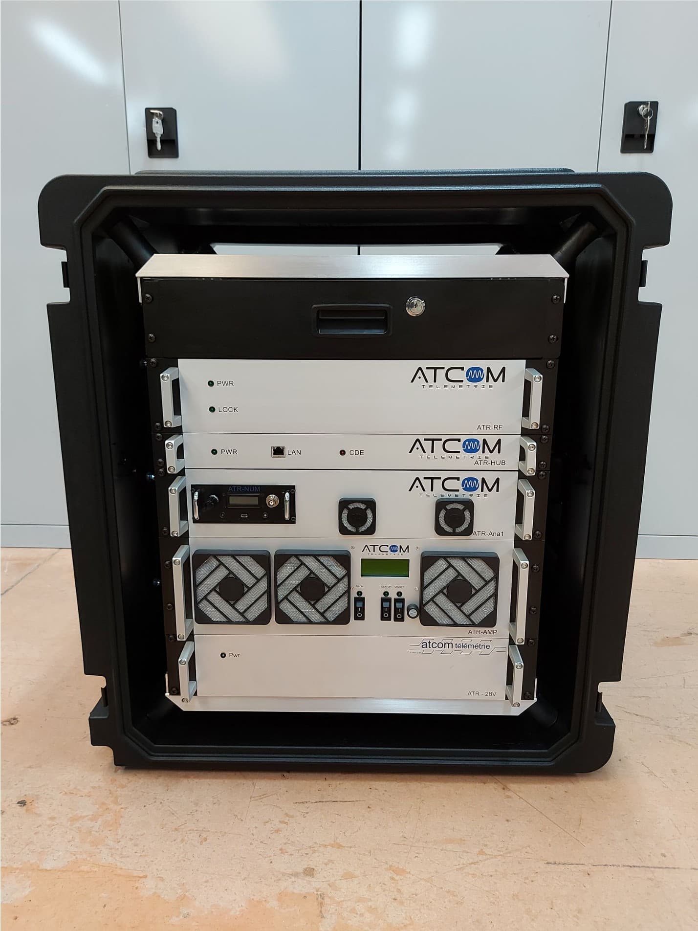
Click to zoom
Application Details
- Equipment Class
- JAD - Part 15 Class A Digital Device
- Date of Grant
- Dec 15, 2022
- Application Purpose
- Original Equipment
- Date of Application
- Dec 15, 2022
- Equipment Note
- Inductive power supply and communication system for telemetry
- Company
- Atcom Telemetrie
- Country
- France
Documents & Files
Document Text
Text extracted from the exhibit documents filed with the FCC. Open a document above to read the original.
Users Manual
ATCOM Télémétrie 2022 User Manual Aeronautical Reception Chain AT_CRA AT_CRA User Manual Equipment: AT_CRA Commercial and marketing support: Arnaud MANSION Business director 15 rue Jean Bertin 45430 Chécy Tel. +33.238.466.300 Email: [email protected] Technical support: Anthony Millot Technical manager 15 rue Jean Bertin 45430 Chécy Tel. +33.238.466.300 Email: [email protected] Ce document et les informations qu'il contient sont la propriété d’ATCOM Télémétrie. Ils ne peuvent être utilisés, reproduits ou communiqués à un tiers sans l'autorisation préalable et écrite d’ATCOM Télémétrie. This document and the information it contains are the property of ATCOM Télémétrie. They may not be used, reproduced or transmitted to a third part without prerequisite and written approval of ATCOM Télémétrie. 2 AT_CRA Revision history DateAuthorRevisionChanges 27/07/2022A. Millot1.0First version Ce document et les informations qu'il contient sont la propriété d’ATCOM Télémétrie. Ils ne peuvent être utilisés, reproduits ou communiqués à un tiers sans l'autorisation préalable et écrite d’ATCOM Télémétrie. This document and the information it contains are the property of ATCOM Télémétrie. They may not be used, reproduced or transmitted to a third part without prerequisite and written approval of ATCOM Télémétrie. 3 AT_CRA Table of contents 1. Product conformity.............................................................................................................................5 2. Safety guide lines................................................................................................................................6 3. General overview................................................................................................................................7 3.1. Aeronautical telemetry................................................................................................................8 4. Operation...........................................................................................................................................9 4.1. Installation...................................................................................................................................9 4.2. Start-up sequence......................................................................................................................10 4.3. New embedded telemetry configuration..................................................................................11 4.4. Shutdown sequence..................................................................................................................13 5. Receiver station description.............................................................................................................14 5.1. ATR_AMP : Induction power source module.............................................................................14 5.2. ATR_RF : Radio module..............................................................................................................16 5.3. ATR_HUB : Ethernet module.....................................................................................................17 5.4. ATR_Ana1 : Main analog module...............................................................................................18 5.5. ATR-28V.....................................................................................................................................20 Ce document et les informations qu'il contient sont la propriété d’ATCOM Télémétrie. Ils ne peuvent être utilisés, reproduits ou communiqués à un tiers sans l'autorisation préalable et écrite d’ATCOM Télémétrie. This document and the information it contains are the property of ATCOM Télémétrie. They may not be used, reproduced or transmitted to a third part without prerequisite and written approval of ATCOM Télémétrie. 4 AT_CRA 1.Product conformity This equipment has been tested and found to comply with the limits for a Class A digital device, pursuant to part 15 of the FCC Rules. These limits are designed to provide reasonable protection against harmful interference when the equipment is operated in a commercial environment. This equipment generates, uses, and can radiate radio frequency energy and, if not installed and used in accordance with the instruction manual, may cause harmful interference to radio communications. Operation of this equipment in a residential area is likely to cause harmful interference in which case the user will be required to correct the interference at his own expense. This device complies with part 15 of the FCC Rules. Operation is subject to the following conditions: (1) This device may not cause harmful interference, and (2) this device must accept any interference received, including interference that may cause undesired operation. FCC ID : 2A88I-AT-CRA The product complies with the applicable Union harmonization legislation: •DIRECTIVE 2014/30/EU OF THE EUROPEAN PARLIAMENT AND OF THE COUNCIL of February 26, 2014 dealing with electromagnetic compatibility. •DIRECTIVE 2006/95/EC OF THE EUROPEAN PARLIAMENT AND OF THE COUNCIL of 12 December 2006 relating to the safety of equipment. Ce document et les informations qu'il contient sont la propriété d’ATCOM Télémétrie. Ils ne peuvent être utilisés, reproduits ou communiqués à un tiers sans l'autorisation préalable et écrite d’ATCOM Télémétrie. This document and the information it contains are the property of ATCOM Télémétrie. They may not be used, reproduced or transmitted to a third part without prerequisite and written approval of ATCOM Télémétrie. 5 AT_CRA 2.Safety guide lines The use of this product is reserved exclusively for measurement. Any other application is considered incompatible with the intended use of the equipment. To insure the safe operation of the device, it must be operated according to the instructions in the user manual. In addition, regulations and related safety information must be complied with. WAR…
Text truncated - open the document above for the full version.
Cover Letter(s)
Atcom Telemetrie 15 rue Jean Bertin 45430 Chécy France To Federal Communications Commission 7435 Oakland Mills Road Columbia, MD 21046-1609 Timco Engineering, Inc. 849 NW State Road 45 Newbeery, Florida 32669 – USA Date:12/12/2022 Re:Confidentiality Request Ladies and Gentlemen: Short-term Confidentiality: This request for confidentiality is made pursuant to 47 CFR 0.457(d)(2) and 0.459 of FCC rules. Atcom Telemetry requests that the following documents regarding this submission for FCC ID: 2A88I-AT-CRA are kept confidential for a period of 180 days from the date of the Grant of Equipment Authorization. 1.Internal Photos 2.External Photos 3.User Manual 4.Test Setup Photos The material above contains technical data, which would customarily be guarded from competitors.
External Photos
AT_CRATechnical Documentation FCC ID 2A88I-AT-CRA Publication History VersionDateModification description 01November 4, 2022 Creation of the document AT_CRA Technical Documentation External Photos Open front view Version : 01 Page 2/12 AT_CRA Technical Documentation External Photos Open rear view Version : 01 Page 3/12 AT_CRA Technical Documentation External Photos Front View Version : 01 Page 4/12 AT_CRA Technical Documentation External Photos Rear View Version : 01 Page 5/12 AT_CRA Technical Documentation External Photos Right side View Version : 01 Page 6/12 AT_CRA Technical Documentation External Photos Left side View Version : 01 Page 7/12 AT_CRA Technical Documentation External Photos Top View Version : 01 Page 8/12 AT_CRA Technical Documentation External Photos Botom View Version : 01 Page 9/12 AT_CRA Technical Documentation External Photos External In/Out (1) Version : 01 Page 10/12 Mini USB Ethernet RJ45 AT_CRA Technical Documentation External Photos External In/Out (2) Version : 01 Page 11/12 SMB connectors Analog ± 5V Outputs BNC connector Data input AT_CRA Technical Documentation External Photos In/Out (3) Version : 01 Page 12/12 Inductive N connector Power supply output Mains Power input 100/230 V AC
ID Label/Location Info
Technical Documentation Label Location FCC ID 2A88I-AT-CRA Publication History Version Date Modification description 01 December 15, 2022 Creation of the document Technical Documentation Label Location Version : 01 Page 2/2 The Label will be located on the upper part of the Product (Blue rectangle) 3D DRAWING Label Location View
ID Label/Location Info
Technical Documentation Label FCC ID Publication History VersionDateModification description 01December 13, 2022 Creation of the document Technical Documentation Label Label View (1) Version : 01 Page 2/2
Internal Photos
AT_CRATechnical Documentation Internal Photos FCC ID2A88I-AT-CRA Publication History VersionDateModification description 01November 8, 2022 Creation of the document AT_CRA Technical Documentation Internal Photos Device AT_CRA_ATR_NUM Open View Version : 01 Page 2/14 AT_CRA Technical Documentation Internal Photos Electronic Card AT_CRA_ATR_NUM Recto verso View Version : 01 Page 3/14 AT_CRA Technical Documentation Internal Photos Device AT_CRA_ATR_AMP Open View Version : 01 Page 4/14 AT_CRA Technical Documentation Internal Photos Electronic Card Recto/ Verso AT_CRA_ATR_AMP View (1) Version : 01 Page 5/14 AT_CRA Technical Documentation Internal Photos Electronic Card Recto/ Verso AT_CRA_ATR_AMP View (2) Version : 01 Page 6/14 AT_CRA Technical Documentation Internal Photos Device AT_CRA_ATR_RF Open View Version : 01 Page 7/14 AT_CRA Technical Documentation Internal Photos Electronic Card Recto/ Verso AT_CRA_ATR_RF View Version : 01 Page 8/14 AT_CRA Technical Documentation Internal Photos Device AT_CRA_ATR_HUB Open View Version : 01 Page 9/14 AT_CRA Technical Documentation Internal Photos Electronic Card Recto/ Verso AT_CRA_ATR_HUB View Version : 01 Page 10/14 AT_CRA Technical Documentation Internal Photos Device AT_CRA_ATR_Ana1 Open View Version : 01 Page 11/14 AT_CRA Technical Documentation Internal Photos Electronic Card Recto/ Verso AT_CRA_ATR_Ana1 View (1) Version : 01 Page 12/14 AT_CRA Technical Documentation Internal Photos Electronic Card Recto/ Verso AT_CRA_ATR_Ana1 View (2) Version : 01 Page 13/14 AT_CRA Technical Documentation Internal Photos Device AT_CRA_ATR_28V Open View (3) Version : 01 Page 14/14
Test Report
This document shall not be reproduced, except in full, without the written approval of the LCIE. This document contains results related only to the items tested. It does not imply the conformity of the whole production to the items tested. Unless otherwise specified or rule defined by the test method, the decision of conformity doesn’t take into account the uncertainty of measures. This document doesn’t anticipate any certification decision TEST REPORT N°: 13407699 - 775412 Version : 02 Subject Electromagnetic compatibility (EMC) : FCC CFR 47 Part 15, Subpart B of 2019 ANSI C63.4 of 2014 ICES-003 issue 7 of 2020 Issued to ATCOM TELEMETRIE 15 rue Jean Bertin – BP 79 45430 Checy France Apparatus under test Product AT_CRA Inductive power supply and communication system for telemetry Trade mark Atcom Télémétrie Manufacturer Atcom Télémétrie Model under test AT_CRA Serial number 2210001 Test date February 28, 2022 Test location LCIE, Villebon Designation Number FR0010 Registration Number 582868 Test performed by Willy Daclinat Composition of document 21 pages Document issued on November 23, 2022 Written by : Approved by : Willy Daclinat Julien Boutaud Tests operator Technical manager TEST REPORT N° 13407699-775412 Version : 02 Page 2/21 FCCpart15 Rev04/05/2021 PUBLICATION HISTORY Each new edition of this test report replaces and cancels the previous edition. The control of the old editions of report is under responsibility of client. Version Date Author Modification 01 April 1, 2022 Willy DACLINAT Creation of the document 02 November 23, 2022 Ali AKEB Correction of the model Name/Manufacturer Adding FCC accreditation information Date of receipt of test item February 28, 2022 TEST REPORT N° 13407699-775412 Version : 02 Page 3/21 FCCpart15 Rev04/05/2021 SUMMARY 1. TEST PROGRAM ................................................................................................................................................... 4 2. EQUIPMENT DESCRIPTION (DECLARED BY PROVIDER) ............................................................................... 5 3. MEASUREMENT OF RADIATED EMISSIONS .................................................................................................... 8 4. MEASUREMENT OF CONDUCTED DISTURBANCE ........................................................................................ 15 5. UNCERTAINTIES CHART ................................................................................................................................... 21 TEST REPORT N° 13407699-775412 Version : 02 Page 4/21 FCCpart15 Rev04/05/2021 1. Test Program References ✓ CFR 47 Part 15 Subpart B - Radio frequency devices - Unintentional radiators 2019 ✓ ICES -003 issue 7 of 2020 ✓ ANSI 63.4 of 2014 Emission tests: Test Description Main characteristics Test result - Comments Measurement of radiated electric field in shielded room 15.109 (a), (b) & (c) Class A Class B PASS FAIL NA NP (Limited Program) Measurement of radiated electric field in open space Class A Class B PASS FAIL NA NP (Limited Program) Measurement of conducted disturbance on the AC main power port 15.107 (a) (c) (d) Class A Class B PASS FAIL NA (1) NP (Limited Program) (1): EUT not directly or indirectly connected to the AC Power Public Network The product is compliant according to CFR 47 Part 15 Subpart B - Radio frequency devices - Unintentional radiators & ICES -003 standards. PASS: EUT complies with standard’s requirement FAIL: EUT does not comply with standard’s requirement NA: Not Applicable NP: Test Not Performed TEST REPORT N° 13407699-775412 Version : 02 Page 6/21 FCCpart15 Rev04/05/2021 Inputs/outputs - Cable: Access Inputs / Outputs Type Length used (m) Declared <3m Shielded Under test Comments Main power supply Input L1-N-PE 2 Yes Data Input BNC 15 No Power supply Output Others 15 No RF-N Connector Network Bidirectionel RJ45 15 No Auxiliary equipment used during test: Type Reference Sn Comments Pc Model : 501U C7N0bC26156128F - - - - - Equipment information: (Declared by provider) Apparatus Description Telemetry system intended to carry out vibration measurements via strain gauges placed in the turbine of a turbojet. This product is intended for use on the ground in test benches.EUT Type of power source: AC power supply DC power supply Battery (Select Type) Test source voltage: Vmin-Vmax: 85 - 264 V / 47 - 63 Hz Vnom VDc Operating Modes Mode 1 All components of the system are in functioning. The system is fully operational Mode 2 - Mode 3 - Mode 4 - TEST REPORT N° 13407699-775412 Version : 02 Page 7/21 FCCpart15 Rev04/05/2021 2.2. EQUIPMENT LABELLING No labelling Equipment Labelling 2.3. EQUIPMENT MODIFICATIONS None Modification: 2.4. FIELD STRENGTH CALCULATION The field strength is calculated by adding the Antenna Factor and Cable Factor, and subtracting the Amplifier Gain (if any) from the measured reading. The basic equation with a sample calculation is as follow: FS = RA + AF + CF – AG Where FS = Field Strength RA = Receiver Amplitude AF = Antenna Factor CF = Cable Factor AG = Amplifier Gain Assume a receiver reading of 52.5dBμV is obtained. The antenna factor of 7.4 and a cable factor of 1.1 are added. The amplifier gain of 29dB is subtracted, giving a field strength of 32 dBμV/m. FS = 52.5 + 7.4 + 1.1 – 29 = 32 dBμV/m The 32 dBμV/m value can be mathematically converted to its corresponding level in μV/m. Level in μV/m = Common Antilogarithm [(32dBμV/m)/20] = 39.8 μV/m. TEST REPORT N° 13407699-775412 Version : 02 Page 8/21 FCCpart15 Rev04/05/2021 3. Measurement of radiated emissions 3.1. ENVIRONMENTAL CONDITIONS Test performed by : Willy Daclinat Date of test : February 28, 2022 Ambient temperature : 18°C Relative humidity : 40% 3.2. TEST SETUP Specifications: Frequency 30 – 1000 MHz RBW 120 kHz 1-6GHz RBW 1MHz Detector Peak and Quasi-Peak Pre characterization in semi anechoic room is performed to define the critical frequencies Op…
Text truncated - open the document above for the full version.
Test Setup Photos
Technical Documentation Test Set Up Photos FCC ID Publication History Version Date Modification description 01 November 23, 2022 Creation of the document Technical Documentation Test Set Up Photos Version : 01 Page 2/3 Measurement of radiated disturbances. Technical Documentation Test Set Up Photos Version : 01 Page 3/3 Conducted emission measurement
Contact Information
Applicant
Arnaud Mansion(Mr)
Test Firm
LABORATOIRE CENTRAL DES INDUSTRIES ELECTRIQUESPatrick Pereira Teixeira
Technical Specifications
| # | Rule Parts | Frequency Range | Power Output |
|---|---|---|---|
| 1 | 15B | - | - |