2A89W-F230LASER MARKING MACHINE
TAECHU ENGINEERING CO., LTD.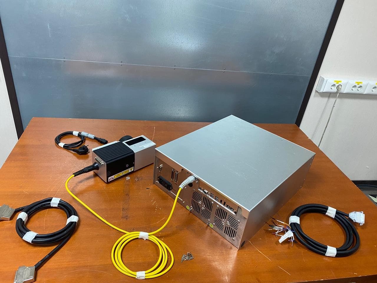
Click to zoom
Application Details
- Equipment Class
- JAD - Part 15 Class A Digital Device
- Date of Grant
- Dec 08, 2022
- Application Purpose
- Original Equipment
- Date of Application
- Dec 08, 2022
- Equipment Note
- LASER MARKING MACHINE
- Company
- TAECHU ENGINEERING CO., LTD.
- Country
- South Korea
Documents & Files
Document Text
Text extracted from the exhibit documents filed with the FCC. Open a document above to read the original.
Users Manual
Revision.1.1 Laser marking system F220 HARDWARE MANUAL Page 2 / 48 F220 Hardware Manual Document Information LegislationR evision History Date Version Description 2022.10.11 1.0 Document Legislated 2022.11.23 1.1 IZI-CODE V0 Renewal Page 3 / 48 F220 Hardware Manual Contents 1. Laser Safety Information ...................................................................................................... 6 1.1 L aser Type ......................................................................................................... 6 1.2 Related Regulation ......................................................................................................... 6 1.3 Management Method ......................................................................................................... 7 1.4 Safety Warning and Sticker Information .................................................................................... 10 2. Laser Introduction and Structure ........................................................................................ 12 2.1 Laser Introduction ................................................................................................. 12 2.2 Before Starting ................................................................................................................... 12 2.3 Structure . .................................................................................................................. 15 2.4 Technical Information .................................................................................................................... 20 3. Laser Operation ................................................................................................................... 22 3.1 Order of Operation ..........................................................................................................................22 3.2 Emergency Stop ............................................................................................................................... 23 3.3 Emergency Stop Release ................................................................................................................ 23 4. User Interface ........................................................................................................ 24 4.1 User Interface Pin Map (D-sub 25P connector) ...................................................................... 24 4.2 Pin description of “User Interface”...................................................................................... 25 4.3 Binary Input Signal Table ......................................................................................................26 4.4 User Interface Connection Examples ............................................................................................27 4.5 Encoder (D-SUB 9P connector) ....................................................................................................31 5. Hardware ....................................................................................................................... 32 5.1 Laser Source ....................................................................................................................... 32 5.2 Scanner ............................................................................................................................................. 33 5.3 Lens ....................................................................................................................................................34 5.4 Control Board ....................................................................................................................... 35 Page 4 / 48 F220 Hardware Manual 5.5 Interface Board ....................................................................................................................... 36 5.6 Power Supply ....................................................................................................................... 37 5.7 Cooling System ....................................................................................................................... 38 6. Maintenance and Repair ..................................................................................................... 39 7. Troubleshooting ................................................................................................................. 40 7.1 Level.1 Abstract .............................................................................................................................. 40 7.2 Level.1 Main Power Failure ........................................................................................................... 41 7.3 Level.1 – Key Switch Error ..................................................................................................... - READY LED Malfunction ......................................................................................................... - Consistent ERROR LED ............................................................................................................42 7.4 Level.1 Laser Shooting Error ...........................................................................................................43 7.5 Level.1 Marking Power Adjustment .............................................................................................44 7.6 Level.1 PC Start Failure ..................................................................................................................45 7.7 Level.1 EZCAD2 Software Driver Error IMC_OpenDriver Fail ...................................................46 8. RMA ...................................................................................................................................47 9. Customer Inquiries ...............................................................................................................48 Page 5 / 48 F220 Hardware Manual ※ Warning This product is a Class 4 laser produ…
Text truncated - open the document above for the full version.
Users Manual
Revision.1.1 Laser marking system F230 HARDWARE MANUAL Page 2 / 48 F230 Hardware Manual Document Information LegislationR evision History Date Version Description 2022.10.11 1.0 Document Legislated 2022.11.23 1.1 IZI-CODE V0 Renewal Page 3 / 48 F230 Hardware Manual Contents 1. Laser Safety Information ...................................................................................................... 6 1.1 L aser Type ......................................................................................................... 6 1.2 Related Regulation ......................................................................................................... 6 1.3 Management Method ......................................................................................................... 7 1.4 Safety Warning and Sticker Information .................................................................................... 10 2. Laser Introduction and Structure ........................................................................................ 12 2.1 Laser Introduction ................................................................................................. 12 2.2 Before Starting ................................................................................................................... 12 2.3 Structure . .................................................................................................................. 15 2.4 Technical Information .................................................................................................................... 20 3. Laser Operation ................................................................................................................... 22 3.1 Order of Operation ..........................................................................................................................22 3.2 Emergency Stop ............................................................................................................................... 23 3.3 Emergency Stop Release ................................................................................................................ 23 4. User Interface ........................................................................................................ 24 4.1 User Interface Pin Map (D-sub 25P connector) ...................................................................... 24 4.2 Pin description of “User Interface”...................................................................................... 25 4.3 Binary Input Signal Table ......................................................................................................26 4.4 User Interface Connection Examples ............................................................................................27 4.5 Encoder (D-SUB 9P connector) ....................................................................................................31 5. Hardware ....................................................................................................................... 32 5.1 Laser Source ....................................................................................................................... 32 5.2 Scanner ............................................................................................................................................. 33 5.3 Lens ....................................................................................................................................................34 5.4 Control Board ....................................................................................................................... 35 5.5 Interface Board ....................................................................................................................... 36 5.6 Power Supply ....................................................................................................................... 37 5.7 Cooling System ....................................................................................................................... 38 6. Maintenance and Repair ..................................................................................................... 39 7. Troubleshooting ................................................................................................................. 40 7.1 Level.1 Abstract .............................................................................................................................. 40 7.2 Level.1 Main Power Failure ........................................................................................................... 41 7.3 Level.1 – Key Switch Error ..................................................................................................... - READY LED Malfunction ......................................................................................................... - Consistent ERROR LED ............................................................................................................42 7.4 Level.1 Laser Shooting Error ...........................................................................................................43 Page 4 / 48 F230 Hardware Manual 7.5 Level.1 Marking Power Adjustment .............................................................................................44 7.6 Level.1 PC Start Failure ..................................................................................................................45 7.7 Level.1 EZCAD2 Software Driver Error IMC_OpenDriver Fail ...................................................46 8. RMA ...................................................................................................................................47 9. Customer Inquiries ...............................................................................................................48 Page 5 / 48 F230 Hardware Manual ※ Warning This product is a Class 4 laser produ…
Text truncated - open the document above for the full version.
Cover Letter(s)
TAECHU ENGINEERING CO., LTD. 1, Deokjeolchangmal-gil, Jeongnam-myeon, Hwaseong-si, Gyeonggi-do, Republic of Korea, 18515 N ovember 7, 2022 Fed eral Communications Commission Authorization and Evaluation Division 7435 Oakland Mills Road, Columbia, MD 21046 T o Whom It May Concern: I, the undersigned, hereby authorize SGS Korea Co., Ltd. and hereafter referred to as SGS Korea, to act on our behalf in all manners relating to application for equipment authorization, including signing of all documents relating to these matters. Any and all acts carried out by SGS Korea Co., Ltd. on our behalf shall have the same effect as acts of our own. I, the undersigned, hereby certify that we are not subject to a denial of federal benefits, that includes FCC benefits, pursuant to Section 5301 of the Anti-Drug Abuse Act of 1988, 21 U.S.C. 853(a). I n authorizing SGS Korea as our agent, we still recognize that we are responsible to: a)c omply with the relevant provisions of the certification program; b ) make all necessary arrangements for the conduct of the evaluation, including provision for examining documentation and access to all areas, records (including internal audit reports) and personnel for the purposes of evaluation (e.g. testing, inspection, assessment, surveillance, reassessment) and resolution of complaints; c)m ake claims regarding certification only in respect of the scope for which certification has been granted; d)d o not use our product certification in such a manner as to bring the Certificatio n D ivision into disrepute and not make any statement regarding our product certificatio n w hich the Certification Division may consider misleading or unauthorized; e)u pon suspension or cancellation of certification, discontinue use of all advertising matter TAECHU ENGINEERING CO., LTD. 1, Deokjeolchangmal-gil, Jeongnam-myeon, Hwaseong-si, Gyeonggi-do, Republic of Korea, 18515 that contains any reference thereto and return any certification documents as required by the Certification Division; f)u se certification only to indicate the products are certified as being in conformity with specified standards; g)en deavor to ensure that no certificate or report nor any part thereof is used in a misleading manner; h ) ensure that any reference to our product certification in communication media such as documents, brochures or advertising, complies with the requirements of the Certification Division; i)k eep a record of all complaints made known to the us relating to the product’s compliance with requirements of the relevant standard and to make these records available to the Certification Division when requested; j)t ake appropriate action with respect to such complaints and any deficiencies found i n p roducts or services that affect compliance with the requirements for certification; k)do cument the actions taken. T his authorization is valid until further written notice from the applicant. S incerely yours, (Sign) Name/Title : Jongyong Sun / Director Company Name : TAECHU ENGINEERING CO., LTD.
Cover Letter(s)
Applicant Declaration Applicant Declaration Rev:0.0 SGS North America Inc. 620 Old Peachtree Road SUITE 100 Suwanee, Georgia 30024 United States Applicant Legal Business Name TAECHU ENGINEERING CO., LTD. Address 1, Deokjeolchangmal-gil, Jeongnam-myeon, Hwaseong-si, Gyeonggi-do, Republic of Korea, 18515 Grantee Code 2A89W FCC ID 2A89W-F230 Authorized Contact Name Jongyong Sun Contact Email [email protected] Contact Phone +82-31-359-9601 I , the undersigned, certify that I am an authorized signatory for the Applicant and therefore declare; a)in ac cordance with 47CFR2.911(d), all of the statements herein and the exhibits attached hereto are true and correct to the best of my knowledge and belief. b)in ac cepting a Grant of Equipment Authorization issued by a TCB, under the authority of the FCC, as a result of the representations made i n t his application, the Applicant is responsible for: (1 ) labeling the equipment with the exact FCC ID as specified in this application, (2) compliance statement labeling pursuant to the applicable rules, (3) compliance of the equipment with the applicable technical rules, c )if the Applicant is not the actual manufacturer of the equipment, appropriate arrangements have been made with the manufacturer to ensur e t hat production units of this equipment will continue to comply with the FCC’s technical requirements. d)in ac cordance with 47 CFR 2.909 and KDB394321, the Applicant has read, understood and agrees to accept t hat they are the responsibl e par ty and agree to abide by t heir responsibilities as specified under 47 CFR 2.909 and KDB394321. e)in ac cordance with ISO17065, FCC KDB641163, FCC KDB610077, KDB394321 and RSP-100, the Applicant has read, understood, accepts and agrees to abide by the post market surveillance requirements . (1 ) the Applicant understands, accepts and agrees that a sample may be requested for surveillance testing. (2) the Applicant shall make provisions to always have a production sample available upon request by SGS, FCC and/or ISED. (3) the Applicant shall, upon request by SGS, at the Applicant’s expense, provide a production sample of the requested product to SGS, FCC and/or ISED as instructed. The sample shall include all support devices, cables, software, accessories or other hardware or software required for evaluation, review, certification and audit surveillance of products certified by SGS. f)neither the Applicant nor any party to the application is subject to a denial of Federal benefits, that includes FCC benefits, pursuant to Section 5301 of the Anti-Drug Abuse Act of 1988, 21 U.S.C. §862 because of a conviction for possession or distribution of a controlled substance. S ee 47C FR 1.2002(b) for the definition of a “party” for these purposes. g)the Applicant has r ead, understood, accepts and agrees to abide by the SGS North America, Inc.(TCB) terms and conditions . Li nk to CFRs: https://www.fcc.gov/wireless/bureau-divisions/technologies-systems-and-innovation-division/rules-regulations-title-47 Link to KDBs: https://apps.fcc.gov/oetcf/kdb/index.cfm Link to RSP-100: https://www.ic.gc.ca/eic/site/smt-gst.nsf/eng/sf01130.html Applicant Signature: Date: 2022-11-07 Print Name: Jongyong Sun Title: Director *NOTE: This declaration cannot be signed by an Agent, it shall be signed by an authorized person listed in the FCC database
Cover Letter(s)
TAECHU ENGINEERING CO., LTD. 1, Deokjeolchangmal-gil, Jeongnam-myeon, Hwaseong-si, Gyeonggi-do, Republic of Korea, 18515 Nobember 07, 2022 Feder al Communications Commission Authorization and Evaluation Division 7435 Oakland Mills Road, Columbia, MD 21046 Re quest of Confidentiality for FCC ID : 2A89W-F230 To Whom It May Concern: Pu rsuant to Sections 0.457 and 0.459 of the Commission’s Rules (CFR 47), and Section 552 (b) (4) of the Freedom of Information Act, TAECHU ENGINEERING hereby requests confidentiality and treatment of certain information accompanying this application. The materials contain trade secrets and proprietary information not customarily released to the public. The public disclosure of these matters might be harmful to the Applicant and provide unjustified benefits to its competitors. We are also hereby request Short -Term Confidentiality for 180 days after the grant as outlined in Public Notice DA 04-1705. This provision will give TAECHU ENGINEERING temporary confidentiality of commercially sensitive information prior to product release. Th e requested Permanent and Temporary Confidential exhibits are listed as follows: CO NFIDENTIAL LIST Permanent 1 Block Diagram 2 Operational Descriptions 3 Schematics 4 - Short-Te r m 4 External Photos 5 Internal Photos 6 Te s t-Setup Photos 7 User’s Manual TAECHU ENGINEERING CO., LTD. 1, Deokjeolchangmal-gil, Jeongnam-myeon, Hwaseong-si, Gyeonggi-do, Republic of Korea, 18515 The Applicant understands that pursuant to Rule 0.457, disclosure of this application and all accompanying documentations, where applicable, will not be made public before the date of the Grant for this application. Sin cerely yours, (Sign) Name/Title : Jongyong Sun / Director Company Name : TAECHU ENGINEERING
Cover Letter(s)
TAECHU ENGINEERING CO., LTD. 1, Deokjeolchangmal-gil, Jeongnam-myeon, Hwaseong-si, Gyeonggi-do, Republic of Korea, 18515 Letter of Declaration Product Equality November 07, 2022 We, as a manufacturer, hereby declare that our product has variant model names as listed below. Variant model is totally same as basic model but it differs in the authentication method that opens the door. Each model differences are described in the below table. Sincerely yours, Jongyong Sun / Director TAECHU ENGINEERING CO., LTD. Tel: +82-31-359-9601 E-mail: [email protected]
External Photos
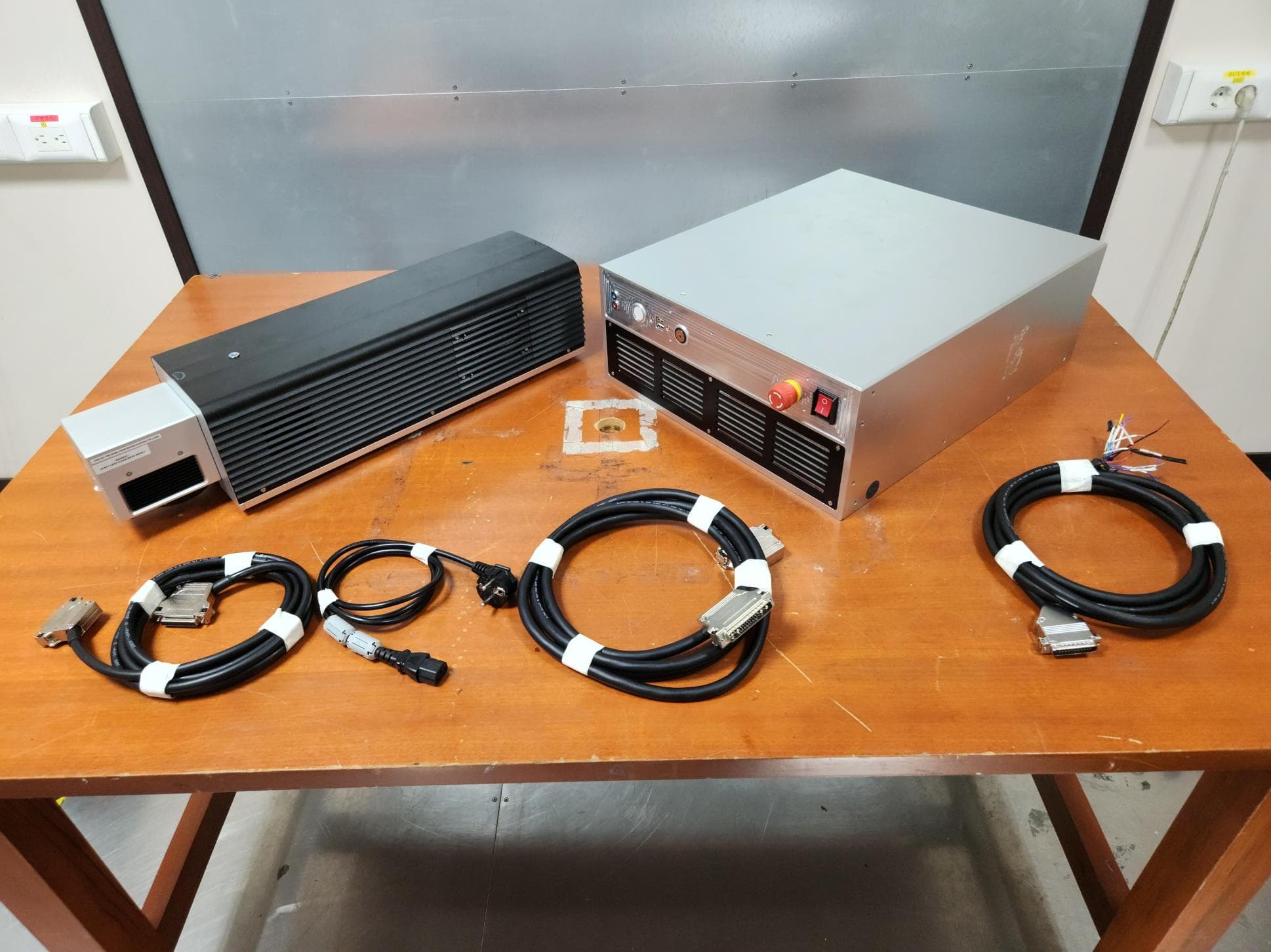
External photos of EUT Front View of EUT Rear View of EUT
External Photos
External photos of EUT Front View of EUT Rear View of EUT
ID Label/Location Info
<Left side view of EUT>
Internal Photos
Internal photos of EUT Inside of EUT ( CONTROLLER ) Inside of EUT ( LASER HEAD ) Inside of EUT ( Controller FIBER LASER SOURCE ) Fr ont View of Controller MAIN BOARD Rear View of Controller MAIN BOARD Fr ont View of Controller Fan Rear View of Controller Fan View of Controller FIBER LASER SOUR CE BOARD View of Controller FIBER LASER SOURCE Sub BOARD Fr ont View of Controller LASER CONTROLLER BOARD Rear View of Controller LASER CON TROLLER BOARD Fr ont View o f Controller REAR BOARD Rear View of Controller REAR BOARD Fr ont View of LASER HEAD SCANNER MOTOR Rear View of LASER HEAD SCANNER MOTOR Fr ont View of LASER HEAD MOTOR CONTROLLER BOARD Rear View of LASER HEAD MOTOR CO NTROLL ER BOAR D View of LASER HEAD LENS Fr ont View of POWER CABLE FERRITE CORE Rear View of POWER CABLE FERRITE CORE Fr on t View of Controller SMPS1 Rear View of Controller SMPS1 Fr ont View of Controller SMPS2 Rea r View of Controller SMPS2 Fr ont V iew of Controller SMPS3 Rear View of Controller S MPS3
Internal Photos
Internal photos of EUT Inside of EUT ( CONTROLLER ) Inside of EUT ( LASER HEAD ) Inside of EUT ( Controller FIBER LASER SOURCE ) Fr ont View of Controller MAIN BOARD Rear View of Controller MAIN BOARD Fr ont V iew of Controller Fan Rear View of Controller Fan View of Controller FIBER LASER SOUR CE BOARD View of Controller FIBER LASER SOURCE Sub BOARD Fr ont View of Controller LASER CONTRO LLER BOARD Rear View of Controller LASER CON TROLLER BOARD F r ont View o f Controller REAR BOARD Rear View of Controller REAR BOARD Fr ont View of LASER HEAD SCANNER MOTOR Rear View of LASER HEAD SCANNER MOTOR Fr ont View of LASER HEAD MOTOR CONTROLLER BOARD Rear View of LASER HEAD MOTOR CONT ROLLER BOARD View of LASER HEAD LENS Fr ont View of POWER CABLE FERRITE CORE Rear View of POWER CABLE FERRITE CORE Fr ont View of Controller SMPS1 Rear View of Controller S MPS1 Fr ont View of Controller SMPS2 Rear View of Controller SMPS2 Fr ont Vi ew of Controller SMPS3 Rear View of Controller SMPS3
Test Report
Test Report No. : F690501-RF-EMC000926 Page : 2 of 16 EMH7081-01A(2021.04.09)(1) A4(210mm*297mm) Contents 1. General Information ................................................................................................... 4 1.1 Client Information ................................................................................................ 4 1.2 Test Laboratory ................................................................................................... 4 1.3 General Information of E.U.T. ............................................................................. 4 1.4 Operating Modes and Conditions ........................................................................ 5 1.5 Peripheral Equipments ........................................................................................ 5 1.6 Cable List ............................................................................................................ 5 1.7 System Configurations ........................................................................................ 6 1.8 Test System Layout ............................................................................................ 6 1.9 Modifications/Notes ............................................................................................. 7 1.10 Applicable Standards for Testing ...................................................................... 7 1.11 Summary of Test Results .................................................................................. 7 2. Emission Test ............................................................................................................ 8 2.1 Test Results ........................................................................................................ 8 2.2 Test Method and Limits ....................................................................................... 8 2.2.1 Test Method ............................................................................................... 8 2.2.2 Test Limits .................................................................................................. 8 2.3 Conducted Disturbance ...................................................................................... 9 2.3.1 Test Equipments ........................................................................................ 9 2.3.2 Test Site ..................................................................................................... 9 2.3.3 Environment Conditions ............................................................................. 9 2.3.4 Test Results ............................................................................................. 10 2.4 Radiated Emission ............................................................................................ 12 2.4.1 Test Equipments ...................................................................................... 12 2.4.2 Test Site ................................................................................................... 12 2.4.3 Environment Conditions ........................................................................... 12 2.4.4 Test Results ............................................................................................. 13 Appendix A : Measurement Uncertainty ...................................................................... 15 Test Report No. : F690501-RF-EMC000926 Page : 3 of 16 EMH7081-01A(2021.04.09)(1) A4(210mm*297mm) Revision History Revision Report number Description 0 F690501-RF-EMC000926 Initial Test Report No. : F690501-RF-EMC000926 Page : 4 of 16 EMH7081-01A(2021.04.09)(1) A4(210mm*297mm) 1. General Information 1.1 Client Information Applicant TAECHU ENGINEERING CO., LTD. Applicant Address 1, Deokjeolchangmal-gil, Jeongnam-myeon, Hwaseong-si, Gyeonggi-do, 18515, Republic of Korea Manufacturer TAECHU ENGINEERING CO., LTD. Manufacturer Address 1, Deokjeolchangmal-gil, Jeongnam-myeon, Hwaseong-si, Gyeonggi-do, 18515, Republic of Korea 1.2 Test Laboratory Name and Address SGS Korea Co., Ltd. - Giheung Laboratory 35, Giheungdanji-ro 121beon-gil, Giheung-gu, Yongin-si, Gyeonggi-do, Republic of Korea - Gunpo Laboratory 4, LS-ro 182beon-gil, Gunpo-si, Gyeonggi-do, 15807, Republic of Korea - Dongtan Laboratory 12, Dongtansandan 10-gil, Hwaseong-si, Gyeonggi-do, 18487, Republic of Korea FCC Registration No. KR0150 Phone + 82 31 548 0710 Fax + 82 31 427 2370 e-mail [email protected] 1.3 General Information of E.U.T. Classification Specification Product Name LASER MARKING MACHINE Model Name F220 Basic Model Name F230 Model Differences - IZI-CODE F220/F230 is assembled with a controller and a marking head. Both of these models are built with the same hardware components such as the scanner, control board, interface board, power supply, and cooling system. Therefore, the dimension of controller and marking head are identical. However, each model uses a different type of laser source. - IZI-CODE F220 laser source has 20W or slightly more average output power and a full-power frequency range of 25~600 ㎑. Moreover, the power consumption is less than 110 W, and the power supply current requirements are more than 5 A. The net weight is about 3.75 Kg. - IZI-CODE F230 laser source has 30W or slightly more average output power and a full-power frequency range of 37~600 ㎑. Moreover, the power consumption is less than 150 W, and the power supply current requirements are more than 7 A. The net weight is about 4.25 Kg. * The description above specifies the difference of each models(F220 and F230) laser source. Other specification details including the dimension of the laser source are the same. Serial No. - EMI Classification Class A Test Voltage AC 120 V, 60 ㎐ Rated Power AC (100-240) V, 50/60 ㎐, 650 W Internal Clock Frequency 2.3 ㎓ H/W Version IZI-CODE_V0 S/W Version 14.11 Test Report No. : F690501-RF-EMC000926 Page : 5 of 16 EMH7081-01A(2021.04.09)(1) A4(210mm*297mm) Port USB Port 1~6, Encoder Port, Inter…
Text truncated - open the document above for the full version.
Test Report
Test Report No. : F690501-RF-EMC000927 Page : 2 of 16 EMH7081-01A(2021.04.09)(1) A4(210mm*297mm) Contents 1. General Information ................................................................................................... 4 1.1 Client Information ................................................................................................ 4 1.2 Test Laboratory ................................................................................................... 4 1.3 General Information of E.U.T. ............................................................................. 4 1.4 Operating Modes and Conditions ........................................................................ 4 1.5 Peripheral Equipments ........................................................................................ 5 1.6 Cable List ............................................................................................................ 5 1.7 System Configurations ........................................................................................ 6 1.8 Test System Layout ............................................................................…
Text truncated - open the document above for the full version.
Contact Information
Applicant
Jongyong Sun(Director)
Technical Contact
SGS Korea Co., LtdJinhyoung Cho
[email protected]+82316880901
4, LS-ro, 182 beon-gil · Gunpo-si, Gyeonggi-do · South Korea
Non-Technical Contact
SGS Korea Co., LtdJacy Kim
[email protected]82-31-428-5886
Test Firm
SGS Korea Co., LtdHwang Gihee
Technical Specifications
| # | Rule Parts | Frequency Range | Power Output |
|---|---|---|---|
| 1 | 15B | - | - |
Other Applications from TAECHU ENGINEERING CO., LTD.
2A89W-C210
Dec 08, 2022LASER MARKING MACHINE
Equipment Class
JAD - Part 15 Class A Digital Device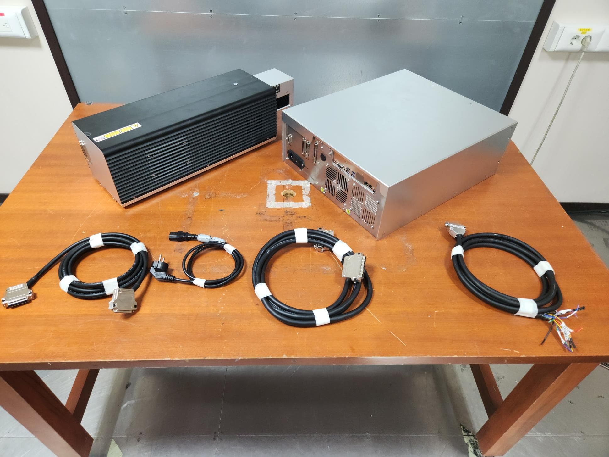
2A89W-C230
Dec 08, 2022LASER MARKING MACHINE
Equipment Class
JAD - Part 15 Class A Digital Device