2A8AC-BRRC1190MODThe BR-RC1190-Mod is a multi-channel RF transceiver module designed for GFSK operation using the Embedded RC232 protocol.
Broy Engineering Ltd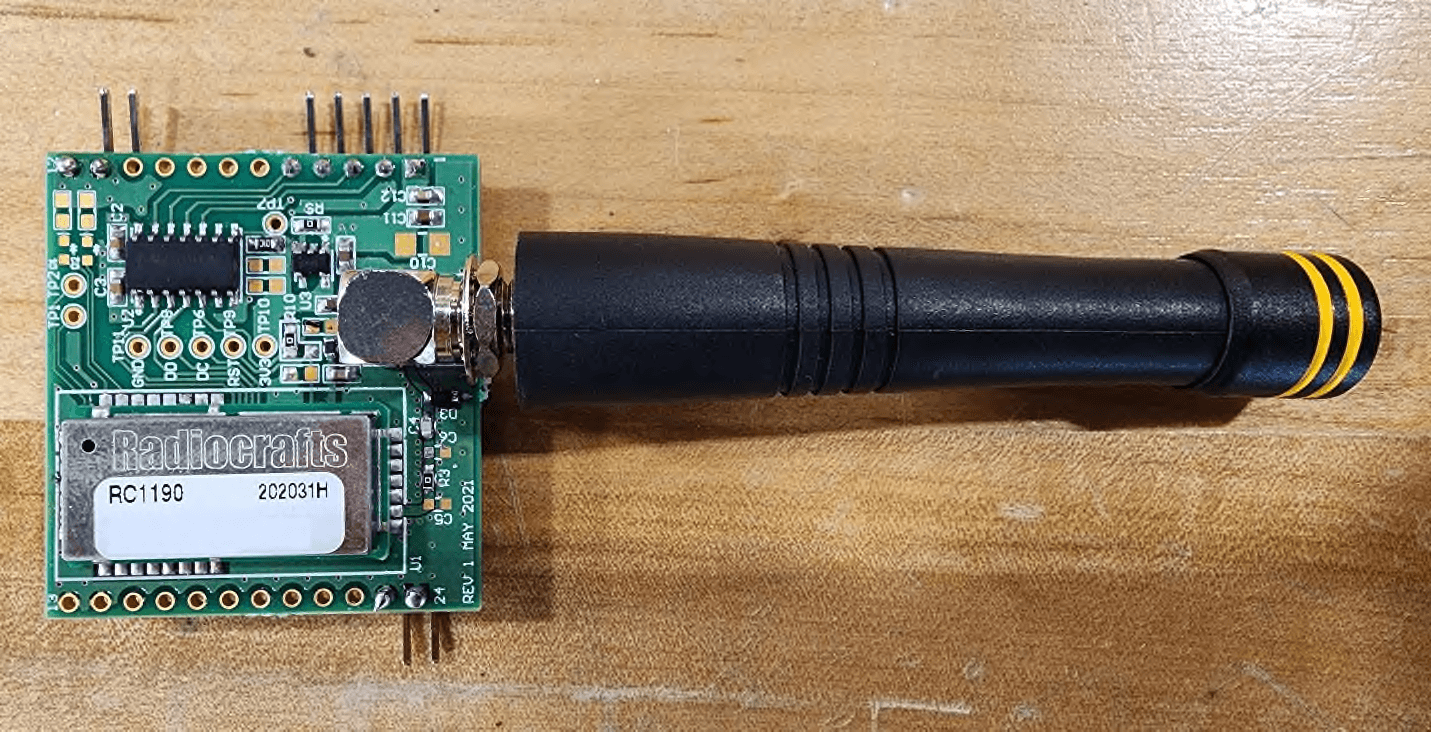
Click to zoom
Application Details
- Equipment Class
- DXX - Part 15 Low Power Communication Device Transmitter
- Date of Grant
- Dec 14, 2022
- Application Purpose
- Original Equipment
- Date of Application
- Dec 14, 2022
- Equipment Note
- The BR-RC1190-Mod is a multi-channel RF transceiver module designed for GFSK operation using the Embedded RC232 protocol.
- Frequency Range
- 902.50000000 - 927.00000000
- Company
- Broy Engineering Ltd
- Country
- Canada
Documents & Files
Document Text
Text extracted from the exhibit documents filed with the FCC. Open a document above to read the original.
Users Manual
BR-RC1190-Mod User Guide Dec 12, 2022 Rev A5 BR-RC1190-Mod User Guide 92 Advance Rd. Toronto, ON. M8Z 2T7 Canada Tel: 416 231 5535 www.broy.com Contents Functional Description .................................................................................................................................................................................... 3 Overview .................................................................................................................................................................................................... 3 Applications ................................................................................................................................................................................................ 3 Radio Performance ..................................................................................................................................................................................... 3 Power Modes ............................................................................................................................................................................................. 3 Interfaces ........................................................................................................................................................................................................ 4 Power Supplies ........................................................................................................................................................................................... 4 Module Reset ............................................................................................................................................................................................. 4 RF Antenna Interface.................................................................................................................................................................................. 4 Data Interfaces ........................................................................................................................................................................................... 4 Pin Definition .................................................................................................................................................................................................. 4 Pinout ......................................................................................................................................................................................................... 4 Electrical Specifications ................................................................................................................................................................................... 4 Absolute Maximum Ratings ....................................................................................................................................................................... 4 Recommended Operating Conditions ........................................................................................................................................................ 5 Mechanical Specifications ............................................................................................................................................................................... 5 Qualifications and Approvals .......................................................................................................................................................................... 5 Country Approvals ...................................................................................................................................................................................... 5 FCC Compliance .......................................................................................................................................................................................... 5 FCC Statement ......................................................................................................................................................................................... 5 FCC RF Exposure Warning ....................................................................................................................................................................... 6 ISED Compliance......................................................................................................................................................................................... 6 ISED Regulatory Statements .................................................................................................................................................................... 6 RF Exposure Warning .............................................................................................................................................................................. 6 Cet équipement est conforme avec ISED RSS-102 des limites d'exposition aux rayonnements définies pour un environnement non contrôlé. Cet émetteur ne doit pas être colocalisé ou fonctionner en association avec une autre antenne ou émetteur. ...................... 7 End-Product User Manual Instructions ...................................................................................................................................................... 7 End-Product Labeling Requirements .......................................................................................................................................................... 7 End-Product Compliance ............................................................................................................................................................................ 7 Approved Antenna ..............................................................................................................…
Text truncated - open the document above for the full version.
Cover Letter(s)
92 Advance Rd. Toronto, ON. M8Z 2T7 Canada Tel: 416 231 5535 www.broy.com 15/11/2022 Federal Communications Commission Equipment Authorization Branch 7435 Oakland Mills Road Columbia, MD 21046 Confidentiality Request regarding application for certification of FCC ID: 2A8AC-BRRC1190MOD Pursuant to Sections 0.457(d)(1)(ii) and 0.459 of the Commission’s Rules, Broy Engineering Ltd hereby requests permanent confidential treatment of information accompanying this application as outlined below: Schematics Bill of Materials/Parts List Block Diagrams Theory of Operation The above materials contain trade secrets and proprietary information not customarily released to the public. The public disclosure of these materials may be harmful to the applicant and provide unjustified benefits to its competitors. The applicant understands that pursuant to Section 0.457 of the Rules, disclosure of this application and all accompanying documentation will not be made before the date of the Grant for this application. Sincerely, David Fancie Engineering Department Broy Engineering Ltd 92 Advance Road Toronto, ON, M8Z 2T7 [email protected] Office: 416 231 5535 ext. 230 Mobile: 905 758 8462
Cover Letter(s)
92 Advance Rd. Toronto, ON. M8Z 2T7 Canada Tel: 416 231 5535 www.broy.com 15/11/2022 Timco Engineering, Inc. 849 NW State Road 45, Newberry, Florida 32669, USA Dear Sir or Madam, We, Broy Engineering Ltd, hereby authorize Amir Emami of Megalab Group Inc., 150 Addison Hall Circle, Aurora, Ontario, L4G 3X8, Canada; 905-752-1925 to act as our agent in all matters relating to applications for equipment authorization, including the signing of all documents relating to these matters. The authorization expires on May 15, 2023. Yours sincerely, David Fancie Engineering Department Broy Engineering Ltd 92 Advance Road Toronto, ON, M8Z 2T7 [email protected] Office: 416 231 5535 ext. 230 Mobile: 905 758 8462
External Photos
Report No.: MEGA290694-RF00Issue Date: December 7, 2022 Megalab Group Inc. – 150 Addison Hall Circle, Aurora, Ontario, L4G 3X8, Canada www.megalabinc.com – (905) 752-1925 This report may not be reproduced, except in full, without prior written approval of Megalab Group Inc. Page 1 of 2 Client:Broy Engineering Ltd Product Name/Model:BR-RC1190-Mod FCC ID:2A8AC-BRRC1190MOD IC:28892-BRRC1190MOD External Photos Note: DUT is a PCB module with no enclosure. Figure 1 – Front without Antenna Report No.: MEGA290694-RF00Issue Date: December 7, 2022 Megalab Group Inc. – 150 Addison Hall Circle, Aurora, Ontario, L4G 3X8, Canada www.megalabinc.com – (905) 752-1925 This report may not be reproduced, except in full, without prior written approval of Megalab Group Inc. Page 2 of 2 Figure 2 – Front with Antenna Figure 3 – Back
ID Label/Location Info
Report No.: MEGA290694-RF00Issue Date: November 22, 2022 Megalab Group Inc. – 150 Addison Hall Circle, Aurora, Ontario, L4G 3X8, Canada www.megalabinc.com – (905) 752-1925 This report may not be reproduced, except in full, without prior written approval of Megalab Group Inc. Page 1 of 1 Client:Broy Engineering Ltd Product Name/Model:BR-RC1190-Mod FCC ID:2A8AC-BRRC1190MOD IC:28892-BRRC1190MOD Sample Label and Location Figure 1 ‒ Sample Label Figure 2 ‒ Label Location LABEL LOCATION
Internal Photos
Report No.: MEGA290694-RF00Issue Date: December 7, 2022 Megalab Group Inc. – 150 Addison Hall Circle, Aurora, Ontario, L4G 3X8, Canada www.megalabinc.com – (905) 752-1925 This report may not be reproduced, except in full, without prior written approval of Megalab Group Inc. Page 1 of 2 Client:Broy Engineering Ltd Product Name/Model:BR-RC1190-Mod FCC ID:2A8AC-BRRC1190MOD IC:28892-BRRC1190MOD Internal Photos Note: DUT is a PCB module with no enclosure. Figure 1 – Front without Antenna Figure 2 – Front, Radiocrafts Shield Removed Report No.: MEGA290694-RF00Issue Date: December 7, 2022 Megalab Group Inc. – 150 Addison Hall Circle, Aurora, Ontario, L4G 3X8, Canada www.megalabinc.com – (905) 752-1925 This report may not be reproduced, except in full, without prior written approval of Megalab Group Inc. Page 2 of 2 Figure 3 – Front with Antenna Figure 4 – Back
RF Exposure Info
Report No.: MEGA290694-RF00Issue Date: November 22, 2022 Megalab Group Inc. – 150 Addison Hall Circle, Aurora, Ontario, L4G 3X8, Canada www.megalabinc.com – (905) 752-1925 This report may not be reproduced, except in full, without prior written approval of Megalab Group Inc. Page 1 of 3 Client:Broy Engineering Ltd Product Name/Model:BR-RC1190-Mod FCC ID:2A8AC-BRRC1190MOD ReferenceFCC KDB 447498 D04 v01 FCC RF Exposure Where the Device Under Test (DUT) can be shown to meet the requirements for an exemption pursuant to FCC 47 CFR §1.1307(b)(3), an evaluation is not required with respect to the limits on human exposure to RF emissions provided in FCC 47 CFR §1.1310. 1.Determination of Exemption As per 47 CFR §1.1307(b)(3), for single RF sources (i.e., any single fixed RF source, mobile device, or portable device), a single RF source is exempt if: A.1-mW Test Exemption: The available maximum time-averaged power is no more than 1 mW, regardless of separation distance. This exemption may not be used in conjunction with other exemption criteria other than those in paragraph (b)(3)(ii)(A) of this section. Medical implant devices may only use this exemption and that in paragraph (b)(3)(ii)(A); B.SAR-Based Exemption: The available maximum time-averaged power or effective radiated power (ERP), whichever is greater, is less than or equal to the threshold P th (mW) described in the following formula. This method shall only be used at separation distances (cm) from 0.5 centimeters to 40 centimeters and at frequencies from 0.3 GHz to 6 GHz (inclusive). P th is given by: ( ) = ( 20 ⁄ ) ≤20 20 < ≤40 Where = − 60 And ( ) = 2040 0.3 ≤ <1.5 3060 1.5 ≤ ≤6 d = the minimum separation distance (cm) in any direction from any part of the device antenna(s) or radiating structure(s) to the body of the device user. Report No.: MEGA290694-RF00Issue Date: November 22, 2022 Megalab Group Inc. – 150 Addison Hall Circle, Aurora, Ontario, L4G 3X8, Canada www.megalabinc.com – (905) 752-1925 This report may not be reproduced, except in full, without prior written approval of Megalab Group Inc. Page 2 of 3 C.MPE-Based Exemption: Using Table 1 and the minimum separation distance (R in meters) from the body of a nearby person for the frequency (f in MHz) at which the source operates, the ERP (watts) is no more than the calculated value prescribed for that frequency. For the exemption in Table 1 to apply, R must be at least λ/2π, where λ is the free-space operating wavelength in meters. If the ERP of a single RF source is not easily obtained, then the available maximum time- averaged power may be used in lieu of ERP if the physical dimensions of the radiating structure(s) do not exceed the electrical length of λ/4 or if the antenna gain is less than that of a half-wave dipole (1.64 linear value). Table 1 of § 1.1307(b)(3)(i)(C) - Single RF Sources Subject to Routine Environmental Evaluation RF SourceFrequency (MHz) Threshold ERP (Watts) 0.3-1.341,920 R 2 1.34-303,450 R 2 /f 2 30-3003.83 R 2 300-1,5000.0128 R 2 f 1,500-100,00019.2 R 2 2.RF Exposure Evaluation The DUT is a mobile device designed to be used in other than fixed locations and generally used in such a way that the RF source's radiating structure could be within 40 centimeters of the body of the user. The DUT could be handheld during configuration and the minimum separation distance from the radiating structure to any part of the body or extremity of a user could be 5mm as worst case as stated by the manufacturer. 2.1DUT RF Output Power Evaluation Frequency (MHz) Max Average Conducted Power (dBm) Rated Output Power (dBm) Antenna Gain (dBi) Max Measured ERP (dBm) Max Measured ERP (mW) Minimum Separation Distance (cm) 926.96N/A-5-0.3-3.60.440.5 Note: 1.EIRP (dBm) = Sum of the conducted power (dBm) + Antenna Gain (dBi) 2.ERP (dBm) = EIRP (dBm) – 2.15 3.ERP (dBm) = E (dBuV/m) + 20log(distance (m)) – 104.8 – 2.15 4.ERP (mW) = 10^((ERP(dBm))/10) Report No.: MEGA290694-RF00Issue Date: November 22, 2022 Megalab Group Inc. – 150 Addison Hall Circle, Aurora, Ontario, L4G 3X8, Canada www.megalabinc.com – (905) 752-1925 This report may not be reproduced, except in full, without prior written approval of Megalab Group Inc. Page 3 of 3 2.21-mW Test Exemption Evaluation Frequency (MHz) Highest Measured Time- Averaged Output Power (dBuV/m) Highest Measured Time- Averaged Output Power ERP (mW) Limit (mW) 926.9693.80.441.00 According to 47 CFR §1.1307(b)(3)(i)(A), this device complies with the RF exposure test exemption.
Test Report
Megalab Group Inc. – 150 Addison Hall Circle, Aurora, Ontario, L4G 3X8, Canada www.megalabinc.com – (905) 752-1925 This report may not be reproduced, except in full, without prior written approval of Megalab Group Inc. RF_FCC249_v1 RF Test Report Standard(s):FCC Part 15 Subpart 15.249, RSS-210 Issue 10:2019 Unlicensed Intentional Radiators Issued To:Broy Engineering Ltd 92 Advance Rd Toronto, Ontario, M8Z 2T7 Canada Product Name:BR-RC1190-Mod Model:BR-RC1190-Mod FCC ID:2A8AC-BRRC1190MOD IC:28892-BRRC1190MOD Report No.MEGA290694-RF00 Date of Issue:December 7, 2022 Report Prepared By:ReviewedBy: Amir Emami, Project EngineerRaymond Au, Project Engineer Report No.: MEGA290694-RF00Issue Date: December 7, 2022 Page 2 of 22 Table of Contents 1. Revision History .................................................................................................................................... 3 2. Summary of Test Results ....................................................................................................................... 4 2.1 Test Verdict ................................................................................................................................... 4 2.2 Test Standards............................................................................................................................... 5 2.3 Test Facility ................................................................................................................................... 6 3. General Information ............................................................................................................................. 8 3.1 Client Information ......................................................................................................................... 8 3.2 Device Under Test (DUT) ............................................................................................................... 8 3.3 Test Setup of DUT ......................................................................................................................... 9 3.4 Modifications for Compliance ....................................................................................................... 9 4. Test Results ......................................................................................................................................... 10 4.1 Maximum Output Power ............................................................................................................ 10 4.2 Spurious Radiated Emissions ...................................................................................................... 12 4.3 Emission Bandwidth .................................................................................................................... 19 5. Test Setup Photos ............................................................................................................................... 22 Report No.: MEGA290694-RF00Issue Date: December 7, 2022 Page 3 of 22 1.Revision History Project No. & Revision Report Date Initials Description MEGA290694- RF00 December 7, 2022 AE Initial Release - - - - NOTE: • The latest revision replaces previous revisions. • This report relates only to the sample(s) identified in this report. Report No.: MEGA290694-RF00Issue Date: December 7, 2022 Page 4 of 22 2.Summary of Test Results 2.1Test Verdict Unless otherwise stated, the results shown in this test report relate only to the sample(s) tested. Requirement Test Type Result Remark FCC ISED 15.203 -- Antenna Requirement Pass Omni-Directional RP-SMA with -0.3dBi Gain 15.249(a) RSS-210 B.10(a) Maximum Output Power Pass --- 15.249(d) RSS-210 B.10(b) Transmitter Spurious Radiated Emissions Pass --- 15.205 RSS-GEN (Table 7) Restricted Bands for Intentional Operation Pass --- -- RSS-GEN 6.7 99% Emission Bandwidth Pass --- 15.207 RSS-GEN (Table 4) Power Line Conducted Emissions N/A DUT is a modulewhich isDC powered and does not connect to any mains network N/A = Not Applicable 2.1.1Test Verdict Notes The DUT was mounted in three orthogonal axes and worst-case results were obtained in the X-axis. Worst case results are presented. See the Test Setup Photos for axis details. Antenna details obtained from Antenna Manufacturer’s Datasheet. As per FCC 15.203, the antenna uses a Reverse Polarity connection and has less than 6dBi gain. Report No.: MEGA290694-RF00Issue Date: December 7, 2022 Page 5 of 22 2.2Test Standards Standard Description ANSI C63.4:2014Methods of Measurement of Radio-Noise Emissions from Low- Voltage Electrical and Electronic Equipment in the Range of 9 kHz to 40 GHz ANSI C63.10:2013American National Standard for Testing Unlicensed Wireless Devices CFR 47 FCC 15 Subpart CCode of Federal Regulations –Radio Frequency Devices, Intentional Radiators FCC KDB 558074:2019FCC KDB 558074 Digital Transmission Systems, measurements and procedures ICES-003 Issue 7:2020Digital Apparatus -Spectrum Management and Telecommunications Policy Interference-Causing Equipment Standard RSS-GEN Issue 5:2021General Requirements and Information for the Certification of Radio Apparatus RSS-210 Issue 10:2019Licence-Exempt Radio Apparatus: Category I Equipment ISO 17025:2017General Requirements for the Competence of Testing and Calibration Laboratories Report No.: MEGA290694-RF00Issue Date: December 7, 2022 Page 6 of 22 2.3Test Facility All tests were performed at Megalab Group Inc., located at 150 Addison Hall Circle, Aurora, ON, L4G 3X8, Canada. The 10-meter semi-anechoic chamber for radiated emission and radiated immunity is designed to handle weights of up to 10,000lb and has power capability of over 100A. The turntable is capable of supporting test devices or systems either floor standing or table top of up to 4 meters wide and 3m tall. Conducted emissions, unless otherwise specified, are performed on a 2.44m x 2.48m ground plane and using a 2.44m x 2.48m vertical ground plane if applicable. 2.3.1Accreditations This rep…
Text truncated - open the document above for the full version.
Test Report
– 1 – Revised 4/14/14 Product Description This reduced-height ¼-wave antenna is ready for years of use thanks to a flexible internal helical that is over-molded with a heavy-duty protective jacket. It’s an excellent choice for outdoor applications or for use in adverse environments where the antenna must resist shock, harsh weather and tampering. HD Series antennas attach via an FCC Part 15 compliant RP-SMA connector. Features • Reduced-height helical whip • Excellent performance • Omni-directional pattern • Very low VSWR • Heavy-duty construction • Damage-resistant • Fully weatherized • Flexible main shaft • Part 15 compliant RP-SMA connector • Use with plastic* or metal enclosures * Requires proximity ground plane Electrical Specifications Center Frequency: 916MHz Recom. Freq. Range: 873–958MHz Wavelength: ¼-wave VSWR: ≤ 2.0 typical at center Peak Gain: –0.3dBi Impedance: 50-ohms Connection: RP-SMA Oper. Temp. Range: –30°C to +70°C Electrical specifications and plots measured on a 10.16 cm x 10.16 cm (4.00" x 4.00") reference ground plane ANT-916-CW-HD Data Sheet by Ordering Information ANT-916-CW-HD 10.5 mm (0.41") 45.0 mm (1.77") 65.0 mm (2.56") 12.3 mm (0.48") End View 13.5 mm (0.53”) 6.4 mm (0.25”) 13.5 mm (0.53") 6.0 mm (0.24”) – 2 – by Data Sheet ANT-916-CW-HD VSWR Graph What is VSWR? The Voltage Standing Wave Ratio (VSWR) is a measurement of how well an antenna is matched to a source impedance, typically 50-ohms. It is calculated by measuring the voltage wave that is headed toward the load versus the voltage wave that is reflected back from the load. A perfect match will have a VSWR of 1:1. The higher the first number, the worse the match, and the more inefficient the system. Since a perfect match cannot ever be obtained, some benchmark for performance needs to be set. In the case of antenna VSWR, this is usually 2:1. At this point, 88.9% of the energy sent to the antenna by the transmitter is radiated into free space and 11.1% is either reflected back into the source or lost as heat on the structure of the antenna. In the other direction, 88.9% of the energy recovered by the antenna is transferred into the receiver. As a side note, since the “:1” is always implied, many data sheets will remove it and just display the first number. How to Read a VSWR Graph VSWR is usually displayed graphically versus frequency. The lowest point on the graph is the antenna’s operational center frequency. In most cases, this will be different than the designed center frequency due to fabrication tolerances. The VSWR at that point denotes how close to 50-ohms the antenna gets. Linx specifies the recommended bandwidth as the range where the typical antenna VSWR is less than 2:1. 159 Ort Lane, Merlin, OR, US 97532 Phone: +1 541 471 6256 Fax: +1 541 471 6251 www.linxtechnologies.com Counterpoise Quarter-wave or monopole antennas require an associated ground plane counterpoise for proper operation. The size and location of the ground plane relative to the antenna will affect the overall performance of the antenna in the final design. When used in conjunction with a ground plane smaller than that used to tune the antenna, the center frequency typically will shift higher in frequency and the bandwidth will decrease. The proximity of other circuit elements and packaging near the antenna will also affect the final performance. For further discussion and guidance on the importance of the ground plane counterpoise, please refer to Linx Application Note AN-00501: Understanding Antenna Specifications and Operation. VSWRReflected Power 3:1 2:1 1:1 25% 11% 0% 916MHz991MHz841MHz 1.494
Test Setup Photos
Report No.: MEGA290694-RF00Issue Date: November 22, 2022 Megalab Group Inc. – 150 Addison Hall Circle, Aurora, Ontario, L4G 3X8, Canada www.megalabinc.com – (905) 752-1925 This report may not be reproduced, except in full, without prior written approval of Megalab Group Inc. Page 1 of 6 Client:Broy Engineering Ltd Product Name/Model:BR-RC1190-Mod FCC ID:2A8AC-BRRC1190MOD IC:28892-BRRC1190MOD Test Setup Photos X-AxisY-AxisZ-Axis Figure 1 ‒ DUT Close Up and Orientations Report No.: MEGA290694-RF00Issue Date: November 22, 2022 Megalab Group Inc. – 150 Addison Hall Circle, Aurora, Ontario, L4G 3X8, Canada www.megalabinc.com – (905) 752-1925 This report may not be reproduced, except in full, without prior written approval of Megalab Group Inc. Page 2 of 6 Figure 2 ‒ Radiated Emissions Setup (Worst Case in X-Axis) Report No.: MEGA290694-RF00Issue Date: November 22, 2022 Megalab Group Inc. – 150 Addison Hall Circle, Aurora, Ontario, L4G 3X8, Canada www.megalabinc.com – (905) 752-1925 This report may not be reproduced, except in full, without prior written approval of Megalab Group Inc. Page 3 of 6 Figure 3 ‒ Spurious Radiated Emissions Setup 9kHz – 30MHz Report No.: MEGA290694-RF00Issue Date: November 22, 2022 Megalab Group Inc. – 150 Addison Hall Circle, Aurora, Ontario, L4G 3X8, Canada www.megalabinc.com – (905) 752-1925 This report may not be reproduced, except in full, without prior written approval of Megalab Group Inc. Page 4 of 6 Figure 4 ‒ Fundamental Emission and Spurious Radiated Emissions Setup 30MHz – 1GHz Note: As per ANSI C63.10-2013 Clause 6.3.1, below 1GHz, the height of the DUT was set to 80cm. Above 1GHz, the height was raised to 1.5m. Report No.: MEGA290694-RF00Issue Date: November 22, 2022 Megalab Group Inc. – 150 Addison Hall Circle, Aurora, Ontario, L4G 3X8, Canada www.megalabinc.com – (905) 752-1925 This report may not be reproduced, except in full, without prior written approval of Megalab Group Inc. Page 5 of 6 Figure 5 ‒ Harmonics and Spurious Radiated Emissions Setup 1GHz – 10GHz Note: As per ANSI C63.10-2013 Clause 6.3.1, above 1GHz, the height of the DUT was set to 1.5m. Report No.: MEGA290694-RF00Issue Date: November 22, 2022 Megalab Group Inc. – 150 Addison Hall Circle, Aurora, Ontario, L4G 3X8, Canada www.megalabinc.com – (905) 752-1925 This report may not be reproduced, except in full, without prior written approval of Megalab Group Inc. Page 6 of 6 Figure 6 ‒ Bandwidth Measurement Setup
Contact Information
Applicant
David Fancie(Engineering)
Test Firm
Megalab Group Inc.Raymond Au
[email protected]905-752-1925
Technical Specifications
| # | Rule Parts | Frequency Range | Power Output | Emission |
|---|---|---|---|---|
| 1 | 15C | 902.5 MHz - 927 MHz | - | 171KF7D |