2A8AP-LS300LS300 Sensor and Relay
Lacuna Space Ltd.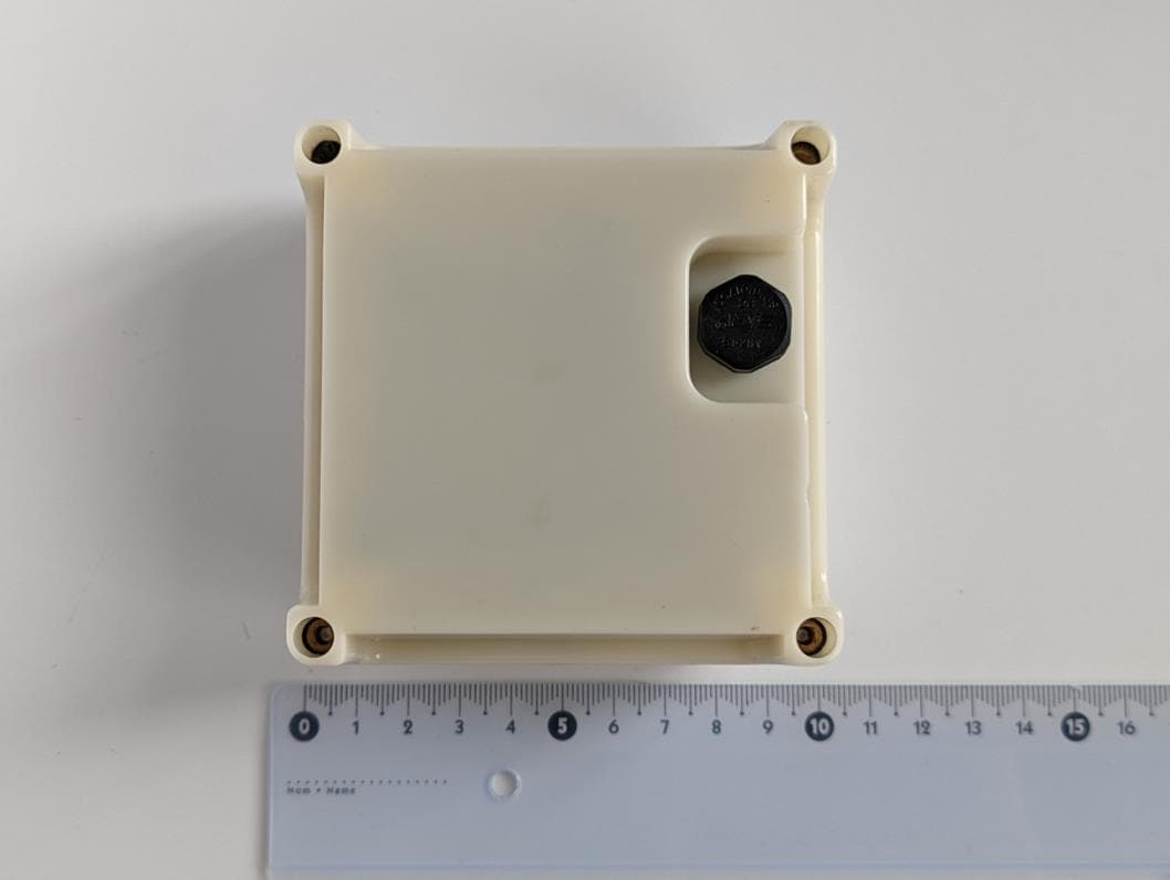
Click to zoom
Application Details
- Equipment Class
- TNB - Licensed Non-Broadcast Station Transmitter
- Date of Grant
- Apr 16, 2023
- Application Purpose
- Original Equipment
- Date of Application
- Apr 16, 2023
- Equipment Note
- LS300 Sensor and Relay
- Frequency Range
- 2000.00000000 - 2010.00000000
- Company
- Lacuna Space Ltd.
- Country
- United Kingdom
Documents & Files
Document Text
Text extracted from the exhibit documents filed with the FCC. Open a document above to read the original.
Users Manual
LS300 Sensor and Relay Wireless satellite terminal with integrated multi-band circularly polarized antenna system FEATURES • 862-870 MHz or 902-928 MHz RHCP antenna • MSS S-band RHCP antenna • GNSS RHCP antenna • 84 x 84 x 20 (mm) without casing • 94 x 94 x 45 (mm) with casing LS300 SENSOR AND RELAY https://lacuna.space DESCRIPTION The LS300 Sensor and Relay has been designed for direct communication with the Lacuna satellite network. The terminal is battery powered and is based around a dual-core ARM M4/M0+ processor. The terminal contains a number of sensors, a GNSS receiver and has an integrated Right Hand Circularly Polarized (RHCP) satellite antenna, providing a 110° wide beam. The terminal should be used outdoors and is contained in a protective enclosure. The terminal communicates with the satellite network in both SRD/ISM- Band as well as in the S-Band. It can be ordered in two different SRD/ ISM frequency band configurations: 862-870 MHz or 902-928 MHz. The S-Band antenna is tuned to 1980-2200 MHz (1980-2010 MHz uplink, 2170-2200 MHz downlink) for both configurations. APPLICATIONS The primary applications of the terminal are direct communication of (internal) sensor data to the satellite network and relay of data received from third party LoRaWAN ® compatible sensors or devices. As such the device is ideally suited for getting acquainted with the services offered by the Lacuna satellite network. The device may also be used as a reference design for third parties wishing to develop their custom designs. APPLICATIONS TECHNICAL SUPPORT • Satellite communication • Low power wireless relay • LPWAN device Lacuna Space Ltd. R104 Rutherford Appleton Laboratory Harwell Campus Didcot England OX11 0QX [email protected] Part numbers LS300 SENSOR AND RELAY Part NumberFreq (MHz)Battery holder LS300-868-A8683 x AA alkaline battery holder LS300-915-A9153 x AA alkaline battery holder https://lacuna.space LS300-XXX-A Where: -XXX refers to frequency option: 868 for 862-870 MHz, 915 for 902-928 MHz Warning: The use of certified protected batteries is mandatory General Data ParameterValueComments Operating temperature-20°C to 55°C Characteristic Impedance50 ohm Weight 215 gramIncluding casing, excluding batteries Dimensions (Board)84*84*20 (mm)Battery holder not considered Dimensions (Casing)94*94*45 (mm)Includes casing and battery holder Battery3 AA alkaline Mounting holesM3 -18 -16 -14 -12 -10 -8 -6 -4 -2 0 2 -180-120-60060120180 Realized Gain (dBic) Theta angle (°) SRD/ISM 868 MHz radiation pattern Gain RHCP Gain LHCP -18 -16 -14 -12 -10 -8 -6 -4 -2 0 2 -180-120-60060120180 Realized Gain (dBic) Theta angle (°) SRD/ISM 915 MHz radiation pattern Gain RHCP Gain LHCP -18 -16 -14 -12 -10 -8 -6 -4 -2 0 2 -180-120-60060120180 Realized Gain (dBic) Theta angle (°) GNSS 1.575 GHz radiation pattern Gain RHCP Gain LHCP Parameter868/915 band * GNSSS-Band Frequency Range (MHz) 862-870902-9281500-17001950-2250 Typical Frequency (MHz)87091515752000 (up)2180 (down) Peak Total Gain (dBi) ** 1.691.751.312.682.78 Peak RHCP Gain (dBic) ** 1.491.620.992.511.53 Average Gain (dBi) ** -2.3-2.2-2.74-1.77-2.85 Total Efficiency (max)49%50%37%46%45% Axial Ratio (dB)< 6< 6< 6< 6< 6 Reflection coefficient (dB)< -10< -10< -6< -6< -6 Peak EIRP (dBm) *** 23.6923.75N/A26.51N/A RF Characteristics * Model variant 868: LS300-868-A, Model variant 915: LS300-915-A ** Values for “Typical Frequency” *** Hardware maximum. Transmissions will be limited in software according to regional regulations. -21 -18 -15 -12 -9 -6 -3 0 3 -180-120-60060120180 Realized Gain (dBic) Theta angle (°) S-band uplink 2000 MHz radiation pattern Gain RHCP Gain LHCP -18 -16 -14 -12 -10 -8 -6 -4 -2 0 2 -180-120-60060120180 Realized Gain (dBic) Theta angle (°) GNSS 1.575 GHz radiation pattern Gain RHCP Gain LHCP https://lacuna.space LS300 SENSOR AND RELAY Main components Traditional satellite terminal solutions often are comprised of several macro components, e.g. power supply, modem, amplifiers, splitters, antennas, that are interconnected with coaxial cables. With the LS300 Sensor and Relay terminal all these components are integrated onto a single printed circuit board resulting in a much smaller and power efficient device. All components listed in the table below are surface-mounted, integrated chips that cannot be removed or replaced without damage to the electronics board. The components cannot be used as stand-alone modules. DescriptionMPNManufacturer Ultra-low-power dual core Arm Cortex-M4 MCU 64 MHz, Cortex-M0+ 32 MHz with 512 Kbytes of Flash memory, Bluetooth LE 5.2, 802.15.4, Zigbee, Thread, USB, LCD, AES-256 STM32WB55RESTMicroelectronics LR1120 Low Power Wi-Fi/ GNSS Scanner + LoRa® TransceiverLR1120Semtech S-band Front-end ModuleSE2431L-RSkyworks Quectel LC76F Compact GNSS Module, concurrent reception of GPS, GLONASS, BeiDou and QZSSLC76FQuectel Tri-axis digital accelerometer sensor ± 2g / 4g / 8gKX023-1025-FRKionix Digital humidity, pressure and temperature sensor -40...+85C, 0...100% RH, 300...1100 hPaBME280Bosch Sensortec Digital-switch hall effect sensor 6.9 / 3.2 mTDRV5023AJQLPGMTexas Instruments Fully Integrated Li-Ion, Li-Polymer Charge Management Controller MCP73831T-2ATI/OTMicrochip Technology -16 -14 -12 -10 -8 -6 -4 -2 0 2 4 800820840860880900920940 Peak Gain (dBi) Frequency (MHz) 868/915 Band Peak Total Gain 868 915 * Depending on model variant (LS300-868-A or LS300-915-A) -5 -4 -3 -2 -1 0 1 2 1500 1520 1540 1560 1580 1600 1620 1640 1660 1680 1700 Peak Gain (dBi) Frequency (MHz) GNSS Band Peak Total Gain 0 0.5 1 1.5 2 2.5 3 3.5 4 1950200020502100215022002250 Peak Gain (dBi) Frequency (MHz) S Band Peak Total Gain -21 -18 -15 -12 -9 -6 -3 0 3 -180-150-120-90-60-300306090120150180 Realized Gain (dBic) Theta angle (°) S-band downlink 2180 MHz radiation pattern Gain RHCP Gain LHCP For contact and product information, visit https://lacuna.space ©2023 Lacuna Space Ltd. All rights reserved. About Lacuna Space Low-cost, simple and reliable global…
Text truncated - open the document above for the full version.
Attestation Statements
R104 Rutherford Lab Harwell Campus Didcot OX11 0QX U.S. Agent Designation for Service of Process ATTENTION: Federal Communications Commission Authorization and Evaluation Division 7435 Oakland Mills Road Columbia, MD 21046 USA REGARDING: FCC Certification – Section 2.911(d)(7) Information Designated U.S. Agent Company Name: Approve-IT, Inc. Contact Name: Nathan Grinager Street Address: 8011 34 th Ave South, Suite 342 City/Province/Zip: Bloomington, MN 55425 Telephone No: 651-247-1678 Email: [email protected] FRN #: 0027533835 This letter is to confirm that we (“the Designated U.S. Agent) have accepted the responsibility to act as the Designated U.S. Agent for Service of Process as required by section 47 CFR 2.911(d)(7) on behalf of the Applicant noted below. U.S. Agent Signature: Date: Signed by (Printed Name/Title): Nathan Grinager / Co-President The Applicant acknowledges that they must maintain an agent for no less than one year after terminating all marketing and importation OR the conclusion of any Commission-related proceeding involving the equipment. The applicant further acknowledges their responsibility to inform the FCC whenever the Designated U.S. Agent information above changes. Applicant Company name: Lacuna Space Ltd Grantee Code: 2A8AP Contact Name: Martin von der Ohe Street Address: R104, Rutherford Appleton Laboratory City/Province/Zip: Harwell Campus, OX11 0QX, United Kingdom Telephone No: +447827828624 Email: [email protected] Applicant Signature: Date: 2023-02-23 Signed by (Printed Name/Title): Rob Spurrett, CEO February 22, 2023
Attestation Statements
R104 Rutherford Lab Harwell Campus Didcot OX11 0QX Date: February 22, 2023 Certification Attestation Statements Attn: Federal Communications Commission Authorization and Evaluation Division 7435 Oakland Mills Road Columbia, MD 21046 USA U.S. Agent for service of process: Approve-IT, Inc. 8011 34 th Ave S, Suite 342 Bloomington, MN 55425 USA FCC ID : 2A8AP-LS300 To Whom It May Concern: 47 CFR section 2.911(d)(5)(i) Attestation Statement Lacuna Space Ltd certifies that as of the date of the application the equipment for which authorization is sought is not “covered” equipment 1 prohibited from receiving an equipment authorization pursuant to section 2.903 of the FCC rules. If the equipment for which the applicant seeks authorization is produced by any of the entities identified on the current Covered List, including affiliates or subsidiaries of the named companies, the applicant must include an explanation on why the equipment is not “covered” equipment. 47 CFR section 2.911(d)(5)(ii) Attestation Statement Lacuna Space (“the applicant”) certifies that, as of the date of the filing of this application, the applicant is not identified on the Covered List as an entity producing “covered” equipment. Thank you, Signature Name: Rob Spurrett Title: CEO Company: Lacuna Space Tel # +447827828624 1 - The Commission’s Covered List is published by the Public Safety and Homeland Security Bureau and posted on the Commission’s website. This Covered List, which is periodically updated, identifies particular equipment, produced by particular entities, that constitutes “covered” equipment. https://www.fcc.gov/supplychain/coveredlist .
Attestation Statements
R104 Rutherford Lab Harwell Campus Didcot OX11 0QX U.S. Agent Designation for Service of Process ATTENTION: Federal Communications Commission Authorization and Evaluation Division 7435 Oakland Mills Road Columbia, MD 21046 USA REGARDING: FCC Certification – Section 2.911(d)(7) Information Designated U.S. Agent Company Name: Approve-IT, Inc. Contact Name: Nathan Grinager Street Address: 8011 34 th Ave South, Suite 342 City/Province/Zip: Bloomington, MN 55425 Telephone No: 651-247-1678 Email: [email protected] FRN #: 0027533835 This letter is to confirm that we (“the Designated U.S. Agent) have accepted the responsibility to act as the Designated U.S. Agent for Service of Process as required by section 47 CFR 2.911(d)(7) on behalf of the Applicant noted below. U.S. Agent Signature: Date: Signed by (Printed Name/Title): Nathan Grinager / Co-President The Applicant acknowledges that they must maintain an agent for no less than one year after terminating all marketing and importation OR the conclusion of any Commission-related proceeding involving the equipment. The applicant further acknowledges their responsibility to inform the FCC whenever the Designated U.S. Agent information above changes. Applicant Company name: Lacuna Space Ltd FRN: 0032747784 Gr antee Code: 2A8AP Contact Name: Martin von der Ohe Street Address: R104, Rutherford Appleton Laboratory City/Province/Zip: Harwell Campus, OX11 0QX, United Kingdom Telephone No: +447827828624 Email: [email protected] Applicant Signature: Date: 2023-02-23 Signed by (Printed Name/Title): Rob Spurrett, CEO February 22, 2023
Cover Letter(s)
RAL, R104 Harwell Campus Harwell OX11 0QX Lacuna Space Limited. Registered In England. No. 1067942. Registered office: RAL, R104, Harwell Campus, Harwell, OX11 0QX January 13 th , 2023 Element Materials Technology 100 Frobisher Business Park Malvern Worcestershire WR14 1BX UK To Whom It May Concern: We certify that we are not subject to denial of federal benefits, that includes FCC benefits, pursuant to Section 5301 of the Anti-Drug Abuse ACT of 1988, U.S.C. 862. Further, no party, as defined in 47 CFR 1.2002(b), to the application, is subject to denial of federal benefits, that includes FCC benefits. Thank you for your attention to this matter. Sincerely, Rob Spurrett CEO
Cover Letter(s)
RAL, R104 Harwell Campus Harwell OX11 0QX Lacuna Space Limited. Registered In England. No. 1067942. Registered office: RAL, R104, Harwell Campus, Harwell, OX11 0QX January 16 th , 2023 Federal Communications Commission Authorization and Evaluation Division 7435 Oakland Mills Road Columbia, Maryland 21046 Re: Equipment approval request FCC ID: 2A8AP-LS300 To whom it may concern, We hereby respectfully request equipment approval (original certification) for our LS300 sensor & relay (model variant LS300-915-A). The applicable rule parts are Part 15 (for operations in the 915-928 MHz range) and Part 25 (for operations in the 2000-2010 MHz range and in the 2180-2200 MHz range). All RF, EMC and safety testing was carried out by Element Materials Technology (UK) or their subcontractors. Sincerely, Rob Spurrett CEO
Cover Letter(s)
RAL, R104 Harwell Campus Harwell OX11 0QX Lacuna Space Limited. Registered In England. No. 1067942. Registered office: RAL, R104, Harwell Campus, Harwell, OX11 0QX January 19 th 2023 Federal Communications Commission Authorization and Evaluation Division 7435 Oakland Mills Road Columbia, Maryland 21046 Re: Request for confidentiality FCC ID: 2A8AP-LS300 To whom it may concern, We hereby respectfully request that under the provision of 47 CFR 0.459 and 0.457(d) the documents listed below and attached with this application for certification be provided with confidential status. • Schematics • Operational Description • Block Diagram • Bill of Materials (BOM) Any exhibit / information for which we have requested confidentiality, but which may not be accorded such treatment by the FCC, should be returned to us. The documents listed above contain trade secrets that are treated as confidential by us. Substantial competitive harm to us could result should they be made available to the public. Sincerely, Rob Spurrett CEO
External Photos
External Pictures of LS300 EUT X+ X- Y+ Y- Z+ Z-
ID Label/Location Info
ß11 cm à ß 4.5 cm à Label Label
Internal Photos
Internal Pictures/ transparent case pictures of LS300 EUT In order to provide the best view of the internal components from six sides, a transparent case was used. The case includes the main PCB and antenna PCB, which are permanently fixed to each other (solder connection), and a 3xAA battery holder. Pictures of the PCBs (top/bottom) can be found on page 4. X+ X- Y+ Y- Z+ Z- Main PCB (excluding RF shield) Main PCB (with RF shield) Antenna PCB
Operational Description
Antenna Parameters Parameter 868/915 band* GNSS S-Band Frequency Range (MHz) 862-870 902-928 1500-1700 1950-2250 Typical Frequency (MHz) 870 915 1575 2000 (up) 2180 (down) Peak Total Gain (dBi)** 1.69 1.75 1.31 2.68 2.78 Peak RHCP Gain (dBic)** 1.49 1.62 0.99 2.51 1.53 Average Gain (dBi)** -2.3 -2.2 -2.74 -1.77 -2.85 Total Efficiency < 49% < 50% < 37% < 46% < 45% Axial Ratio (dB) < 6 < 6 < 6 < 6 < 6 Reflection coefficient (dB) < -10 < -10 < -6 < -6 < -6 Peak EIRP (dBm)*** 23.69 23.75 N/A 26.51 N/A * Model variant 868: LS300-868-A, Model variant 915: LS300-915-A ** Values for “Typical Frequency” *** Hardware maximum. Transmissions will be limited in software according to regional regulations. All antennas are integrated RHCP patch antennas. These antennas are custom made for the LS300 devices, which is why they do not have part numbers or drawing numbers. The antennas will be fixed, i.e. not replaceable by other antennas. Gain diagrams * Depending on model variant (LS300-868-A or LS300-915-A) Note: The max peak total gain in this graph is higher than the value specified in the table above. However, the device will never be operated outside of 1980-2010 MHz (TX) and 2170-2200 MHz (RX), which is why “typical” values have been indicated in the table for both transmission directions. -16 -14 -12 -10 -8 -6 -4 -2 0 2 4 800820840860880900920940 Peak Gain (dBi) Frequency (MHz) 868/915 Band Peak Total Gain 868 915 -5 -4 -3 -2 -1 0 1 2 15001520154015601580160016201640166016801700 Peak Gain (dBi) Frequency (MHz) GNSS Band Peak Total Gain 0 0.5 1 1.5 2 2.5 3 3.5 4 1950200020502100215022002250 Peak Gain (dBi) Frequency (MHz) S Band Peak Total Gain Radiation Patterns Note: The radiation patterns for the 868 Band and 915 Band look identical, however they have marginal differences. -18 -16 -14 -12 -10 -8 -6 -4 -2 0 2 -180-120-60060120180 Gain (dBic) Theta angle (°) 868 Band Radiation Pattern Gain RHCP Gain LHCP -18 -16 -14 -12 -10 -8 -6 -4 -2 0 2 -180-120-60060120180 Gain (dBic) Theta angle (°) 915 Band Radiation Pattern Gain RHCP Gain LHCP -18 -16 -14 -12 -10 -8 -6 -4 -2 0 2 -180-120-60060120180 Gain (dBic) Theta angle (°) GNSS Band Radiation Pattern Gain RHCP Gain LHCP -21 -18 -15 -12 -9 -6 -3 0 3 -180-120-60060120180 Gain (dBic) Theta angle (°) S-band 2000 MHz Radiation Pattern Gain RHCP Gain LHCP -20 -15 -10 -5 0 5 -180-120-60060120180 Gain (dBic) Theta angle (°) S-band 2180 MHz Radiation pattern Gain RHCP Gain LHCP
RF Exposure Info
Report Number: TRA-058206-47-01C RF915 8.0 Page 39 of 40 16 Appendix A - MPE Calculation Prediction of MPE limit at a given distance For purposes of these requirements mobile devices are defined by the FCC as transmitters designed to be used in other than fixed locations and to generally be used in such a way that a separation distance of at least 20 centimeters is normally maintained between radiating structures and the body of the user or nearby persons. These devices are normally evaluated for exposure potential with relation to the MPE limits. As the 20 cm separation specified under FCC rules may not be achievable under normal operation of the EUT, an RF exposure calculation is needed to show the minimum distance required to be less than the power density limit, as required under FCC rules. Equation from IEEE C95.1 Where: S = power density R = distance to the centre of radiation of the antenna EIRP = EUT Maximum power Result Channel Frequency (MHz) EIRP (mW) Power density limit (S) (mW/cm 2 ) Distance (R) cm required to be less than the power density limit 2000.2 222.8 1.0 4.2 2005 227.0 1.0 4.3 2009.8 2223.4 1.0 4.2 SS4 arranged-re 4 2 S EIRP R R EIRP S
RF Exposure Info
MPE Calculation Prediction of MPE limit at a given distance For purposes of these requirements mobile devices are defined by the FCC as transmitters designed to be used in other than fixed locations and to generally be used in such a way that a separation distance of at least 20 centimeters is normally maintained between radiating structures and the body of the user or nearby persons. These devices are normally evaluated for exposure potential with relation to the MPE limits. As the 20 cm separation specified under FCC rules may not be achievable under normal operation of the EUT, an RF exposure calculation is needed to show the minimum distance required to be less than the power density limit, as required under FCC rules. Equation from IEEE C95.1 Where: S = power density R = distance to the centre of radiation of the antenna EIRP = EUT Maximum power Result Channel Frequency (MHz) EIRP (mW) Power density limit (S) (mW/cm 2 ) Distance (R) cm required to be less than the power density limit 902 126.5 0.6 4.1 915 122.2 0.6 4.0 927 116.9 0.6 3.9 Note: Evaluation based on maximum conducted power. ππ 4 arranged-re 4 2 S EIRP R R EIRP S==
Test Report
RF916 11.0 Report on the Radio Testing For Lacuna Space on LS300 Report no. TRA-058206-47-00C 2023-03-29 RF916 11.0 REPORT ON THE RADIO TESTING OF A Lacuna Space LS300 WITH RESPECT TO SPECIFICATION FCC 47CFR 15.247 TEST DATE: 2022-12-09 to 2022-12-20 Tested by: Steven Garwell Radio test Engineer Written by: Steven Garwell Radio Test Engineer Approved by: John Charters Department Manager - Radio Date: 2023-03-29 Disclaimers: [1] THIS DOCUMENT MAY BE REPRODUCED ONLY IN ITS ENTIRETY AND WITHOUT CHANGE [2] THE RESULTS CONTAINED IN THIS DOCUMENT RELATE ONLY TO THE ITEM(S) TESTED Report Number: TRA-058206-47-00C Issue: C Report Number: TRA-058206-47-00C RF916 11.0 Page 3 of 56 1 Revision Record Issue Number Issue Date Revision History A 2022-12-06 Original B 2022-12-09 Contact details amended, Typographical corrections C 2023-03-15 Technical corrections throughout document Report Number: TRA-058206-47-00C RF916 11.0 Page 4 of 56 2 Summary TEST REPORT NUMBER: TRA-058206-47-00C WORKS ORDER NUMBER: TRA-058206-01 PURPOSE OF TEST: Certification TEST SPECIFICATION: 47CFR15.247 EQUIPMENT UNDER TEST (EUT): LS300 FCC IDENTIFIER: 2A8AP-LS300 EUT SERIAL NUMBER: 0012 (conducted), 0009 (radiated) MANUFACTURER/AGENT: Lacuna Space ADDRESS: R104 Rutherford Appleton Laboratory Harwell Campus Didcot OX11 0QX United Kingdom CLIENT CONTACT: Rob Spurret +447827828624 [email protected] ORDER NUMBER: LN-PO-042-22 TEST DATE: 2022-12-09 to 2022-12-20 TESTED BY: Steven Garwell Element Report Number: TRA-058206-47-00C RF916 11.0 Page 5 of 56 2.1 Test Summary Test Method and Description Requirement Clause 47CFR15 Applicable to this equipment Result / Note Radiated spurious emissions (restricted bands of operation and cabinet radiation) 15.247(d) PASS AC power line conducted emissions 15.207 Note 1 Carrier frequency separation 15.247 (a) (1) PASS Number of hopping channels 15.247 (a) (1) (i), (ii) and (iii) PASS Average time of occupancy 15.247 (a) (1) (i), (ii) and (iii) PASS Maximum peak conducted output power 15.247 (a) (1), (b)(1) and (b)(2) PASS 20 dB emission bandwidth 15.247 (a) (1) (i) and (ii) PASS Out-of-band emissions 15.247(d) PASS Calculation of duty correction - Client Declaration Specific Note: 1. The EUT is a battery powered device General Notes: The results contained in this report relate only to the items tested, in the condition at time of test, and were obtained in the period between the date of initial receipt of samples and the date of issue of the report. The apparatus was set up and exercised using the configurations, modes of operation and arrangements defined in this report only. Any modifications made are identified in Section 8 of this report. Particular operating modes, apparatus monitoring methods and performance criteria required by the standards tested to have been performed except where identified in Section 5.2 of this test report (Deviations from Test Standards). Report Number: TRA-058206-47-00C RF916 11.0 Page 6 of 56 3 Contents 1 Revision Record ................................................................................................................................ 3 2 Summary ........................................................................................................................................... 4 2.1 Test Summary ........................................................................................................................... 5 3 Contents ............................................................................................................................................ 6 4 Introduction ....................................................................................................................................... 8 5 Test Specifications ............................................................................................................................ 9 5.1 Normative References .............................................................................................................. 9 5.2 Deviations from Test Standards ................................................................................................ 9 6 Glossary of Terms ........................................................................................................................... 10 7 Equipment under Test ..................................................................................................................... 11 7.1 EUT Identification .................................................................................................................... 11 7.2 System Equipment .................................................................................................................. 11 7.3 EUT Mode of Operation .......................................................................................................... 11 7.4 EUT Radio Parameters ........................................................................................................... 11 7.4.1 General ........................................................................................................................... 11 7.4.2 Antennas ......................................................................................................................... 11 7.5 EUT Description ...................................................................................................................... 12 8 Modifications ................................................................................................................................... 12 9 EUT Test Setup .............................................................................................................................. 13 9.1 Block Diagram ......................................................................................................................... 13 9.2 General Set-up Photograph ...............................................................................................…
Text truncated - open the document above for the full version.
Test Report
RF915 8.0 Report on the Radio Testing For Lacuna Space on LS300 Report no. TRA-058206-47-01C 2022-12-09 RF915 8.0 REPORT ON THE RADIO TESTING OF A Lacuna Space LS300 WITH RESPECT TO SPECIFICATION FCC 47CFR 25 TEST DATE: 03 Oct 2022 - 20 Oct 2022 Tested by: Sing Lung Siu Written by: Sing Lung Siu Radio Test Engineer Approved by: John Charters Department Manager - Radio Date: 2023-04-13 Disclaimers: [1] THIS DOCUMENT MAY BE REPRODUCED ONLY IN ITS ENTIRETY AND WITHOUT CHANGE [2] THE RESULTS CONTAINED IN THIS DOCUMENT RELATE ONLY TO THE ITEM(S) TESTED Report Number: TRA-058206-47-01C Issue: A Report Number: TRA-058206-47-01C RF915 8.0 Page 3 of 40 1 Revision Record Issue Number Issue Date Revision History A 2022-10-20 Original B 2022-12-09 Contact details changed C 2023-04-13 Changed wordings and re-plotted part of the graph in Section 13 to clarify the result. Report Number: TRA-058206-47-01C RF915 8.0 Page 4 of 40 2 Summary TEST REPORT NUMBER: TRA-058206-47-01C WORKS ORDER NUMBER: TRA-058206-02 PURPOSE OF TEST: Certification TEST SPECIFICATION: 47CFR25.202, 25.204, 25.216 EQUIPMENT UNDER TEST (EUT): LS300 FCC IDENTIFIER: 2A8AP-LS300 EUT SERIAL NUMBER: 0003, 0009 MANUFACTURER/AGENT: Lacuna Space ADDRESS: R104 Rutherford Appleton Laboratory Harwell Campus Didcot OX11 0QX United Kingdom CLIENT CONTACT: Rob Spurret +447827828624 [email protected] ORDER NUMBER: LN-PO-042-22 TEST DATE: 03 Oct 2022 - 20 Oct 2022 TESTED BY: Sing Lung Siu Element Report Number: TRA-058206-47-01C RF915 8.0 Page 5 of 40 2.1 Test Summary Test Method and Description Requirement Clause 47CFR25 Applicable to this equipment Result / Note Frequency tolerance Clause 25.202(d) Pass Emission Mask Clause 25.202(f) Pass Emission Limitation – Spurious Emission Clause 25.202(f) Pass Power Limits (radiated e.i.r.p.) Clause 25.204 (a) Pass Limits on emissions from mobile earth stations for protection of aeronautical radionavigation- satellite service Clause 25.216 (e) Pass General Notes: The results contained in this report relate only to the items tested, in the condition at time of test, and were obtained in the period between the date of initial receipt of samples and the date of issue of the report. The apparatus was set up and exercised using the configurations, modes of operation and arrangements defined in this report only. Any modifications made are identified in Section 8 of this report. Particular operating modes, apparatus monitoring methods and performance criteria required by the standards tested to have been performed except where identified in Section 5.2 of this test report (Deviations from Test Standards). Report Number: TRA-058206-47-01C RF915 8.0 Page 6 of 40 3 Contents 1 Revision Record ................................................................................................................................ 3 2 Summary ........................................................................................................................................... 4 2.1 Test Summary ........................................................................................................................... 5 3 Contents ............................................................................................................................................ 6 4 Introduction ....................................................................................................................................... 7 5 Test Specifications ............................................................................................................................ 8 5.1 Normative References .............................................................................................................. 8 5.2 Deviations from Test Standards ................................................................................................ 8 6 Glossary of Terms ............................................................................................................................. 9 7 Equipment under Test ..................................................................................................................... 10 7.1 EUT Identification .................................................................................................................... 10 7.2 System Equipment .................................................................................................................. 10 7.3 EUT Mode of Operation .......................................................................................................... 10 7.4 EUT Radio Parameters ........................................................................................................... 11 7.4.1 General ........................................................................................................................... 11 7.4.2 Antennas ......................................................................................................................... 11 7.5 EUT Description ...................................................................................................................... 11 8 Modifications ................................................................................................................................... 12 9 EUT Test Setup ........................................…
Text truncated - open the document above for the full version.
Contact Information
Applicant
Rob Spurrett
Test Firm
Element Materials Technology Warwick LtdNeil Roche
Technical Specifications
| # | Rule Parts | Frequency Range | Power Output | Emission | Tolerance |
|---|---|---|---|---|---|
| 1 | 25 | 2.00 GHz - 2.01 GHz | 122.00 mW | 150KG7D | 0.6000000000 ppm |