2A8EK-RE2000Biometric Time Clock
Workwell Technologies, Inc.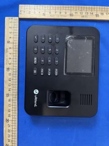
Click to zoom
Application Details
- Equipment Class
- DTS - Digital Transmission System
- Date of Grant
- Mar 06, 2026
- Application Purpose
- Original Equipment
- Equipment Note
- Biometric Time Clock
- Frequency Range
- 2412.00000000 - 2462.00000000
- Company
- Workwell Technologies, Inc.
- Country
- United States
Documents & Files
Document Text
Text extracted from the exhibit documents filed with the FCC. Open a document above to read the original.
Users Manual
RE2000 Biometric Time Clock Product Manual Scan this QR Code or go to support.trackmytime.com for more help setting up your account. QUESTIONS? Call 800-518-8925 or Visit support.trackmytime.com CONTENTS 01 INTRO .....................................................1 02 CREATE YOUR UATTEND ACCOUNT ..........................2 03 ADD DEPARTMENTS ........................................4 04 ADD EMPLOYEES ...........................................6 05 ACTIVATE YOUR TIME CLOCK ................................8 06 WALL MOUNT .............................................10 07 FINGERPRINT TEMPLATES ..................................12 08 USING YOUR KEYPAD ......................................14 09 USING YOUR MENUS .......................................17 10 TROUBLESHOOTING ......................................26 LIMITED WARRANTY ........................................28 SAFETY INFORMATION ..................................... 11 1231 QUESTIONS? Call 800-518-8925 or Visit support.trackmytime.com YOUR TIME CLOCK AT A GLANCE What’s in the Box: • Time clock • Power adapter • Tabletop stand • Mounting plate + screws • Quick Start Guide Clock Features: • Wi-Fi connectivity • Fingerprint + PIN punch options • Supports up to 1000 employees • Supports up to 300 fingerprint templates. • Offline mode will sync with the cloud when connectivity is restored QUESTIONS? Call 800-518-8925 or Visit support.trackmytime.com ? Setting up your uAttend Time Clock requires an interaction between your Time Clock and Cloud Portal. First we’ll begin in the Cloud, then we’ll finish with the Time Clock. Once you’ve completed the following 5 easy steps, your employees will be ready to use the time clock. CREATE YOUR ACCOUNT ACTIVATE YOUR TIME CLOCK HANG YOUR TIME CLOCK ADD EMPLOYEE FINGERPRINTS ADD DEPARTMENTS AND EMPLOYEES INTRODUCTION 01 1 2 3 4 5 QUESTIONS? Call 800-518-8925 or Visit support.trackmytime.com 2 HANG YOUR TIME CLOCK ADD DEPARTMENTS AND EMPLOYEES CREATE YOUR uATTEND ACCOUNT 02 Open your web browser and visit www.TrackMyTime.com/signup then follow the prompts. 1. 2. Here are some helpful tips to make the setup as smooth as possible. Your Dealer ID will be found on the back of your Quick Start Guide. If the Dealer ID is missing, please visit support.trackmytime.com for a list of Dealer IDs. Before you can set up your new uAttend Time Clock, you will need to set up your uAttend Cloud Account. QUESTIONS? Call 800-518-8925 or Visit support.trackmytime.com ? 3. 4. When selecting your plan size, keep in mind that your employees are your hourly workforce. Supervisors (not paid hourly) and administrators are not included in this number. Your plan is month-to-month and can be changed at any time. Your login URL is going to become the “web address” for your company’s uAttend Portal. For example, you can type in “gr8cookieco” to create trackmytime.com/gr8cookieco to represent The Great Cookie Company. trackmytime.com/gr8cookieco QUESTIONS? Call 800-518-8925 or Visit support.trackmytime.com 4 ADD DEPARTMENTS 03 Departments are used to group employees together within the uAttend system. The uAttend Setup Wizard will create a default department, which you can modify as needed. You can create more departments within your account and choose other department settings, such as overtime and punch rounding rules. 1. Select the Departments tab on your Dashboard 2. Select “+ Add Department” 3. Create a Department Code The Department Code is used as a reference on employee time cards to ensure that hours are appropriately allocated to the correct departments. For example, the code for “Sales” can be “SLS.” 4. Enter the full Department Name Specify additional department settings on this screen now or enter that information later. 5. Select... a. “Save & Add New” to add a new department. b. “Save & Continue” to add more rules and policies. c. “Save & Close” to move to the next step. QUESTIONS? Call 800-518-8925 or Visit support.trackmytime.com ? QUESTIONS? Call 800-518-8925 or Visit support.trackmytime.com 6 04 ADD EMPLOYEES 1. Select the People tab on your Dashboard 2. Select “Add Person” 3. Assign that person a role, then add their first and last name Employees are the portion of your workforce that use the time clock to track their time. Supervisors can view and edit time cards, but do not punch in and out of the time clock. Administrators have full access to the account and its settings. Additional administrators can be added for $6 per month, per administrator. 4. Select... a. “Save and Continue” to set up the employee’s profile. b. “Save and Close” to move on to the next steps. You can add more details by going back to that person’s profile at any time. The number of employees you can add to your account is limited by the plan size you have chosen. Add and assign employees to your departments in the uAttend Setup Wizard or simply add them later within your account. Change the size of your plan at any time by selecting your user icon in the upper right corner of your uAttend Portal, then selecting “My Account” from the drop down menu. QUESTIONS? Call 800-518-8925 or Visit support.trackmytime.com ? QUESTIONS? Call 800-518-8925 or Visit support.trackmytime.com 8 1. Plug your clock into a power outlet. a. Follow the onscreen prompts to select your Wi-Fi Network. b. Enter your password onscreen. c. The clock will check for any needed updates once the connection is established, to be sure you have the most up-to- date version of the clock firmware possible! 2. Enter your uAttend Company ID. a. This ID can be found in the upper right corner of your uAttend Web Portal. If you do not have an account, please set one up as outlined in Section 2 of this manual. 05 ACTIVATE YOUR TIME CLOCK QUESTIONS? Call 800-518-8925 or Visit support.trackmytime.com ? 3. Enter the 2-factor Verification Code, emailed to your uAttend Account administrator’s email address. a. This helps to keep your account secure, by ensuring no one can add a clock to …
Text truncated - open the document above for the full version.
Attestation Statements
Workwell Technologies, Inc. 2026-02-02 Eurofins Electrical and Electronic Testing NA, Inc. 914 West Patapsco Avenue Baltimore, MD 21230 RE: Attestation Statements Part 2.911(d)(5)(i) request for (FCC ID: 2A8EK-RE2000) [Workwell Technologies, Inc.] (“the applicant”) certifies that the equipment for which authorization is sought is not “covered” equipment prohibited from receiving an equipment authorization pursuant to section 2.903 of the FCC rules. We also certify that, as of the date of the filing of the application, the equipment does not utilize cyber-security or anti-virus software from Kaspersky Lab, Inc, or any of its successors and assignees, which is also on the “covered list”. Sincerely, Cristal Redman Manager Workwell Technologies, Inc. 2777 Loker Avenue West, Suite A Carlsbad, California 92010, USA Workwell Technologies, Inc. 2026-02-02 Eurofins Electrical and Electronic Testing NA, Inc. 914 West Patapsco Avenue Baltimore, MD 21230 RE: Attestation Statements Part 2.911(d)(5)(ii) request for (FCC ID: 2A8EK-RE2000) [Workwell Technologies, Inc.] (“th e applicant ”) certifies that, as of the dat e of th e filing of the application, the applicant is not identified on the Covered List as an entity producing “covered” equipment. Sincerely, Cristal Redman Manager Workwell Technologies, Inc. 2777 Loker Avenue West, Suite A Carlsbad, California 92010, USA
Attestation Statements
Attestation Statements (2026-02-03) TO: Federal Communications Commission Authorization and Evaluation Division 7435 Oakland Mills Road Columbia, MD 21046, USA RE: Attestation Statements Part 2.911(d)(7) request for (FCC ID: 2A8EK-RE2000) (Workwell Technologies, Inc.), the undersigned, hereby authorize (Workwell Technologies, Inc.) to act as our designated U.S. agent for service of process,( Workwell Technologies, Inc.) accepts to maintain an agent for no less than one year after the grantee has terminated all marketing and importation or the conclusion of any Commission-related proceeding involving the equipment. (Workwell Technologies, Inc.) accepts the responsibility to act as designated U.S. agent for service of process. Applicant Information: Company name: Workwell Technologies, Inc. Contact Name: Cristal Redman Address: 2777 Loker Avenue West, Suite A Carlsbad, California 92010, USA FRN: 0032782971 Telephone No: (650) 520-4759 Email: [email protected] Signature [Cristal Redman ] U.S. Agent Information: Company Name: Workwell Technologies, Inc. Address: 2777 Loker Avenue West, Suite A Carlsbad, California 92010, USA FRN: 0032782971 Contact Name: Cristal Redman Telephone No: (650) 520-4759 Email: [email protected] Signature [Cristal Redman ]
Cover Letter(s)
Workwell Technologies, Inc. 2026-02-03 Eurofins Electrical and Electronic Testing NA, Inc. 914 West Patapsco Avenue Baltimore, MD 21230 RE: LETTER OF AGENT AUTHORIZATION To Whom It May Concern: We, the undersigned, hereby authorize Guangdong Global Testing Technology Co., Ltd. to act on our behalf in all matters relating to application for equipment authorization, including the signing of all documents relating to these matters. We also hereby certify that no party to the application authorized hereunder is subject to the denial of benefits, including FCC benefits, pursuant to Section 5301 of the Anti-Drug Abuse Act of 1988, 21 U.S.C.853(a). This agreement expires one year from the current date. Sincerely, Cristal Redman VP of Product Development Workwell Technologies, Inc. 2777 Loker Avenue West, Suite A Carlsbad, California 92010, USA
Cover Letter(s)
Workwell Technologies, Inc. 2026-02-03 Eurofins Electrical and Electronic Testing NA, Inc. 914 West Patapsco Avenue Baltimore, MD 21230 RE: CONFIDENTIALITY REQUEST FOR (EUT Name: Biometric Time Clock /Model: RE2000/FCC ID: 2A8EK-RE2000) To Whom It May Concern: This letter serves as an official request for confidentiality under sections 0.457 and 0.459 of CFR 47. We have requested that the (Block Diagram, Operational Description, Schematics) required to be submitted with this application be permanently withheld from public review. The above materials contain trade secrets and proprietary information not customarily released to the public. The public disclosure of these materials may be harmful to the applicant and provide unjustified benefits to its competitors. Please contact me if there is any information you may need. Sincerely, Cristal Redman VP of Product Development Workwell Technologies, Inc. 2777 Loker Avenue West, Suite A Carlsbad, California 92010, USA
External Photos
External
Internal Photos
Internal Antenna
RF Exposure Info
RF EXPOSURE EVALUATION According to FCC 1.1310: The criteria listed in the following table shall be used to evaluate the environment impact of human exposure to radio frequency(RF) Radiation as specified in §1.1307(b) FCC ID: 2A8EK-RE2000 EUT Specification EUT Biometric Time Clock Frequency band (Operating) BLE: 2.402GHz ~ 2.480GHz WIFI: 2.412GHz ~ 2.462GHz Device category Portable (<20cm separation) Mobile (>20cm separation) Exposure classification Occupational/Controlled exposure (S = 5mW/cm 2 ) General Population/Uncontrolled exposure (S=1mW/cm 2 ) Antenna diversity Single antenna Multiple antennas Tx diversity Rx diversity Tx/Rx diversity Max. output power IEEE 802.11b: 16.78 dBm IEEE 802.11g: 15.39 dBm IEEE 802.11n HT20: 15.1 dBm IEEE 802.11n HT40: 13.78 dBm Antenna gain (Max) 2.02dBi Evaluation applied MPE Evaluation SAR Evaluation Page 2 of 3 Limits for Maximum Permissible Exposure(MPE) Frequency Range(MHz) Electric Field Strength(V/m) Magnetic Field Strength(A/m) Power Density(mW/cm 2 ) Average Time (A) Limits for Occupational/Control Exposures 300-1500 -- -- F/300 6 1500-100000 -- -- 5 6 (B) Limits for General Population/Uncontrol Exposures 300-1500 -- -- F/1500 6 1500-100000 -- -- 1 30 Friis transmission formula: P d =(P out *G)\(4*pi*R 2 ) Where P d = Power density in mW/cm 2 , P out =output power to antenna in mW. G= gain of antenna in linear scale, Pi=3.1416 R= distance between observation point and center of the radiator in cm=20cm P d the limit of MPE, 1mW/cm 2 . If we know the maximum gain of the antenna and total power input to the antenna, through the calculation, we will know the distance where the MPE limit is reached. For multiple RF sources: Multiple RF sources are exempt if: in the case of fixed RF sources operating in the same time-averaging period, or of multiple mobile or portable RF sources within a device operating in the same time averaging period, if the sum of the fractional contributions to the applicable thresholds is less than or equal to 1 as indicated in the following equation Evaluated k : the maximum reported SAR or MPE of fixed, mobile, or portable RF source k either in the device or at the transmitter site from an existing evaluation at the location of exposure. Exposure Limit k : either the general population/uncontrolled maximum permissible exposure (MPE) or specific Absorption rate (SAR) limit for each fixed, mobile, or portable RF source k. Page 3 of 3 Measurement Result 2.4G WIFI: Mode Max Measured Power (dBm) Tune up tolerance (dBm) Max tune up conducted power(dBm) Output Peak power (mW) Ant. Gain (dBi) Ant. Gain (numeric) Power density at 20cm (mW/ cm 2 ) Power density Limits (mW/ cm 2 ) 802.11b 16.78 17±1 18 63.096 2.02 1.592 0.025356 1 802.11g 15.39 15±1 16 39.811 2.02 1.592 0.015999 1 802.11n HT20 15.1 15±1 16 39.811 2.02 1.592 0.015999 1 802.11n HT40 13.78 14±1 15 31.623 2.02 1.592 0.012708 1 Signature: Shawn Wen Date: 2026-2-6
Test Report
S 承认书 SPECIFICATIONFORAPPROVAL 审批/Approval客户批准/CustomerApproval 制作 PreparedBy 审核 CheckedBy 批准 ApprovalBy 审核 CheckedBy 批准 ApprovalBy 签章 Signature 日期 Date 修订履历/ChangeLog 版本 Version 修订内容 ChangeDescription 责任人 PersoninCharge 核准 ApprovalBy 日期 Date 客户名称 CustomerName 芯毕耐 客户项目名Customer ProjectName 288-A288- 项目名 A 客户编码 CustomerP/N WF029A-1131R-15 料号P/N 0 频段 Band WIFI2.4G 版本号 Version A0 设计人信息/DesignerInformation 射频工程师 RFEngineer 研发主管 R&DDiretor 结构工程师 MEEngineer 目录/Catalogue 序号 No. 项目 Item 页码 PageNo. 1 图纸或实物图片 DrawingorProductImage 4 2 尺寸测量报告 DimensionsTestReport 5 3 射频性能测试报告 RFPerformanceTestReport 6-9 4 可靠性测试报告 ReliabilityTestReport1 10 5 包装文件 PackageDocument 11 6 环境有害物质管控一览表 RoHSControllistforSample 12 7 安装事宜或其它 InstallWizard orOther 12 产品图纸或实物图片 DrawingorProductImage D E S C R I P T I O N N O Q ' T Y 2 1 3 1 R E M A R K 1 5 0 C a b l e ? 1 . 1 3 C a b l e G r e y , 5 0 Ω F P C - 黑 油 黑 字 半 对 半 基 材 , 做 抗 氧 化 处 理 3 M 9 4 7 1 背 胶 F P C 6 5 4 3 2 1 A B X X . X . . X X . X X X . X C H E C K E D ± 1 . 0 D R A W I N G ± 0 . 1 ± 0 . 5 ± 3 . 0 ± 5 F I L E : S H E E T : P A R T N A M E : R E V A 0 U N I T m / m C U S T O M E R : 1 / 1 6 5 4 C D E 3 2 A 0 F R E V DATE N e w I s s u e G D E S C R I P T I O N 1 W F 0 2 9 A - 1 1 3 1 R - 1 5 0 S D C P / N O : W I F I 天 线 ( 2 8 8 - A ) F P C ( 丝 印 S D C 0 2 9 A ) + 1 . 1 3 灰 色 线 + I P E X 1 右 L = 1 5 0 m m 芯 毕 耐 APPROVED 注 : 6 0 m m 以 内 的 线 材 , 若 无 客 户 要 求 则 默 认 端 子 头 朝 下 4 手 撕 位 S D C 0 2 9 A 1 端 子 I P E X 1 全 部 为 通 孔 看 到 的 样品尺寸测量报告 SampleDimensionsTestReport 测试日期 TestDate 样品数量 SampleQty. 3 测试人 Inspector 尺寸编号 DimensionNo. 标准 Standard 样品1 Sample1 样品2 Sample2 样品3 Sample3 Pass/NG ①长度20.98±0.2mm20.982121 Pass ②宽度19.66±0.2mm19.719.6619.7 Pass ③厚度0.1±0.03mm0.10.10.1 Pass ④线长150±2mm150151150 Pass 最终结论 Conclusion PASS 测试人&日期 Inspector&Date 批准&日期 Approval&Date 射频性能测量报告 RFPerformanceTestReport 天线测试设备简介 AntennaTestEquipmentIntroduction 测试天线输入特性使用AgilentE5071CandAgilent5062A矢量网络分析仪;辐射特性利 用广屏三维近场暗室进行测试,并分别使用8960E5515和AgilentE4438C进行了分析。暗房的测 试坐标如下: TestofantennainputcharacteristicsusingAgilentE5071CandAgilent5062Avectornetwork analyzer;Theradiationpatternoftheantennaaretestedusingtheguangping3DnearfieldAnechoicChamber, andtheinstrumentisusedtoagilent8960E5515andAgilentE4438C.Thetestcoordinatesofthedarkroom areasfollows: 1.S11参数测量/S11Parameter-VSWR 使用一根50Ω同轴电缆连接到天线,然后该电缆连接到网络分析仪测量S11参数,被测量产品远离金属至少 20厘米。 MeasuringMethodisa50Ωcoaxialcableisconnectedtotheantenna.Thenthiscableisconnectedtoanetworkanalyzer tomeasuretheS11parameter,Keepingthisfixtureawayfrommetalatleast20cm. S11Parameter-VSWR 2.天线匹配网络/ AntennaMatchingNetwork 3.Gain&Efficiency Frequency(MHz)Efficiency(%)PeakGAIN(dBi) 2400 48.85 1.59 2450 50.62 2.02 2500 49.54 1.93 4.WIFIOTAData 可靠性测试报告 ReliabilityTestReport 测试日期 TestDate 样品数量 SampleQty. 3 测试人 Inspector 测试项目 TestItem 要求 Requirement 试验设备 testing equipment 样品1 Sample1 样品2 Sample2 样品3 Sample3 判定 PASS/NG 高温存储 在+85°C条件下暴露 24H,恢复2H后进行测 试 恒温恒湿箱OKOKOKPass 低温存储 在-40°C条件下暴露 24H,恢复2H后进行测 试 恒温恒湿箱OKOKOKPass 高温工作 在+60°C条件下通电工 作24H 恒温恒湿箱OKOKOKPass 低温工作 在-20°C条件下通电工 作24H 恒温恒湿箱OKOKOKPass 盐雾试验 (5士0.5)%氯化钠、 pH值为6.5~7.2,实 验箱温度(35±2)°C □24H☑48H 盐雾试验机OKOKOKPass 连接器铆压 拉拔力 1.13线径≥10N 0.81线径≥8N RG174≥60N RG178≥50N 推拉力计≥10N≥10N≥10NPass 最终结论 Conclusion Pass 测试人& 日期 Inspector& Date 批准&日期 Approval&D ate 安装事宜或其它 InstallWizardorOther 安装过程: 取1PCS产品,用手撕下FPC背面的离型纸,然后将FPC定位孔位置与外壳定位孔位置(定位筋 位或定位线)对齐,平整的贴附与外壳上,具体位置如下图所示: 安装过程注意事项: □粘贴天线后保证FPC完整贴附于外壳; □定位孔与外壳定位柱位置对齐; □FPC边缘与外壳边缘对齐; □带端子天线在将端子扣合到主板PCBA端时请首先对齐端子,然后垂直扣合; □拆卸天线端子时需使用工具(如专用撬棍)垂直翘起端子,不可直接拽线拆卸。
Test Report
TRF No.: 04-E001-0B TRF Originator: GTG TRF Date: 2023-12-13 Web: www.gtggroup.com E-mail: [email protected] Tel.: 86-400 755 8988 CFR 47 FCC PART 15 SUBPART C TEST REPORT For Biometric Time Clock MODEL NUMBER: RE2000 REPORT NUMBER: E04A26010014F00201 ISSUE DATE: January 30, 2026 FCC ID: 2A8EK-RE2000 Prepared for Workwell Technologies, Inc. 2777 Loker Avenue West, Suite A Carlsbad, California 92010, USA Prepared by Guangdong Global Testing Technology Co., Ltd. Room 101-105, 203-210, Building 1, No.2, Keji 8 Road, Songshan Lake Park, Dongguan city, Guangdong, People’s Republic of China, 523808 This report is based on a single evaluation of the submitted sample(s) of the above mentioned product, it does not imply an assessment of the production of the products. This report shall not be reproduced, except in full, without the written approval of Guangdong Global Testing Technology Co., Ltd. REPORT NO.: E04A26010014F00201 Page 2 of 97 TRF No.: 04-E001-0B Global Testing , Great Quality. Revision History Rev. Issue Date Revisions Revised By V0 January 30, 2026 Initial Issue REPORT NO.: E04A26010014F00201 Page 3 of 97 TRF No.: 04-E001-0B Global Testing , Great Quality. Summary of Test Results Test Item Clause Limit/Requirement Result Antenna Requirement N/A FCC Part 15.203/15.247 (c) Pass AC Power Line Conducted Emission ANSI C63.10-2020, Clause 6.2 FCC Part 15.207 Pass Conducted Output Power ANSI C63.10-2020, Clause 11.9.1.3 FCC Part 15.247 (b)(3) Pass 6dB Bandwidth and 99% Occupied Bandwidth ANSI C63.10-2020, Clause 11.8.1 FCC Part 15.247 (a)(2) Pass Power Spectral Density ANSI C63.10-2020, Clause 11.10.2 FCC Part 15.247 (e) Pass Conducted Band edge and spurious emission ANSI C63.10-2020, Clause 11.11 FCC Part 15.247(d) Pass Radiated Band edge and Spurious Emission ANSI C63.10-2020, Clause 11.11 & Clause 11.12 FCC Part 15.247 (d) FCC Part 15.205/15.209 Pass Duty Cycle ANSI C63.10-2020, Clause 11.6 None; for reporting purposes only. Pass *This test report is only published to and used by the applicant, and it is not for evidence purpose in China. *The measurement result for the sample received is <Pass> according to <CFR 47 FCC PART 15 SUBPART C> when <Accuracy Method> decision rule is applied. REPORT NO.: E04A26010014F00201 Page 4 of 97 TRF No.: 04-E001-0B Global Testing , Great Quality. CONTENTS 1. ATTESTATION OF TEST RESULTS..................................................................................... 5 2. TEST METHODOLOGY......................................................................................................... 6 3. FACILITIES AND ACCREDITATION..................................................................................... 6 4. CALIBRATION AND UNCERTAINTY ................................................................................... 7 4.1. MEASURING INSTRUMENT CALIBRATION ........................................................... 7 4.2. MEASUREMENT UNCERTAINTY ............................................................................ 7 5. EQUIPMENT UNDER TEST .................................................................................................. 8 5.1. DESCRIPTION OF EUT ........................................................................................... 8 5.2. CHANNEL LIST ........................................................................................................ 9 5.3. Maximum Conducted Output Power.......................................................................... 9 5.4. TEST CHANNEL CONFIGURATION ........................................................................ 9 5.5. THE WORSE CASE POWER SETTING PARAMETER .......................................... 10 5.6. DESCRIPTION OF AVAILABLE ANTENNAS ......................................................... 10 5.7. SUPPORT UNITS FOR SYSTEM TEST ................................................................. 11 5.8. SETUP DIAGRAM .................................................................................................. 11 6. MEASURING EQUIPMENT AND SOFTWARE USED......................................................... 12 7. ANTENNA PORT TEST RESULTS ..................................................................................... 14 7.1. Conducted Output Power ........................................................................................ 14 7.2. 6dB Bandwidth and 99% Occupied Bandwidth ....................................................... 15 7.3. Power Spectral Density ........................................................................................... 17 7.4. Conducted Band edge and spurious emission ........................................................ 18 7.5. Duty Cycle .............................................................................................................. 20 8. RADIATED TEST RESULTS ............................................................................................... 21 8.1. Radiated Band edge and Spurious Emission .......................................................... 26 9. ANTENNA REQUIREMENT ................................................................................................ 43 10. AC POWER LINE CONDUCTED EMISSION ......................................................... 44 11. TEST DATA - Appendix A ..................................................................................... 46 REPORT NO.: E04A26010014F00201 Page 5 of 97 TRF No.: 04-E001-0B Global Testing , Great Quality. 1. ATTESTATION OF TEST RESULTS Applicant Information Company Name: Workwell Technologies, Inc. Address: 2777 Loker Avenue West, Suite A Carlsbad, California 92010, USA Manufacturer Information Company Name: SHENZHEN WANGLINFA TECHNOLOGY CORPORATION Address: 2/F Block P, Shang Xia Wei Industrial Area, Sha 3, Shajing, Bao-an District, ShenZhen GuangDong, China EUT Information Product Description: Biometric Time Clock Model: RE2000 Series Model: N/A Brand: uAttendTM Sample Received Date: January 07, 2025 …
Text truncated - open the document above for the full version.
Test Setup Photos
Setup Photographs Radiated Band edge and Spurious Emission AC Power Line Conducted Emission
Contact Information
Applicant
Cristal Redman
[email protected]Fax: (800) 357-0298
Technical Contact
Workwell Technologies, Inc.Cristal Redman
2777 Loker Avenue West · Suite A Carlsbad · United States
Test Firm
Guangdong Global Testing Technology Co., Ltd.Shawn Wen
Technical Specifications
| # | Rule Parts | Frequency Range | Power Output |
|---|---|---|---|
| 1 | 15C | 2.41 GHz - 2.46 GHz | 47.60 mW |