2A8GJ-BSN-W7301Wi-Fi Synchronized Wall Clock
ShenZhen QiZhiZhou MaoYi YouXianGongSi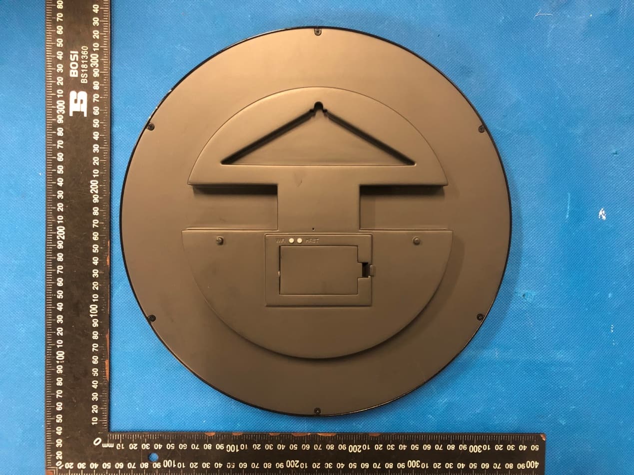
Click to zoom
Application Details
- Equipment Class
- DTS - Digital Transmission System
- Date of Grant
- Sep 18, 2022
- Application Purpose
- Original Equipment
- Date of Application
- Sep 18, 2022
- Equipment Note
- Wi-Fi Synchronized Wall Clock
- Frequency Range
- 2412.00000000 - 2462.00000000
- Country
- China
Documents & Files
Document Text
Text extracted from the exhibit documents filed with the FCC. Open a document above to read the original.
Users Manual
BBoA Ase n ™™ Wi-Fi Synchronized Wall Clock User Manual BSN-W7300/BSN-W7400 Series A——Mounting hole B——Wi-Fi button C——HRST button D——Battery Compartment (with cover) Quick start overview Your Boasen clock can automatically calibrate its time and switch to daylight saving time based on your time zone selection. Setup is very simple, install the battery, connect to its hotspot then the settings web page will pop up. Usually,if the guessed time zone is exactly what you need, you only need to set the Wi-Finetwork for it.The general operating steps are outlined below: 1. Install 2 AA batteries correctly. 2. Connect to your Boasen clock via its Wi-Fi hotspot. 3. Open the settings web page that usually pops up automatically. 4. Set up Wi-Fi network. 5. Set up your time zone. 6. Save Settings and install the clock wherever you like. 1. Install AA Batteries Open the battery compartment on the back of the clock. Insert two AA batteries, using the plus (+) and minus (-) guides in the AA battery pack battery compartment to insert the batteries in the proper direction.Insert the plus (+) endfirst and you can easily install the batteries. Additional Information: The working voltage of your Boasen clock is 2.7V~3.5V, 2 AA batteries are required. It is recommended to use alkaline batteries or 1.5V constant voltage output AArechargeable Batteries. Better battery quality can extend battery replacement cycles. When replacing the battery, remove the plus (+) endfirst. If it is too tight to remove, it is recommended to use an appropriate small tool. The battery compartment cover also works. However, it may cause slight damage to its appearance surface. 2. Connect to Your Boasen ClockHotspot Your Boasen clock provides an open Wi-Fi hotspotfor setting it up, which you can connect using your smartphone, PAD, laptop or desktop computer, etc. The way to do this is to look for an open Wi-Fi network starting with "Boasen -Clock" and select it to connect. 3. Open the Settings Web Page After the connection is established, your device will automatically pop up the settings page, or prompt you to log in. Tap the prompt to open the settings page in a pop-up window. You can follow the prompts to set it up when you see the settings page. Basically, it only takes two steps to complete the setup: Step 1: Set up Wi-Fi network. (See section 4) Step 2: Set up you time zone. (See section 5) 4. Set up Wi-Fi Network Selectthe Wi-Fi network that you want to use.If it doesn't appear in the drop-down list, you can tap "Wi-Fi Scan" to refresh and wait a few seconds interval until you see it. For hidden networks, you need to type the network SSID manually. 5. Set up YourTime Zone If your wall clock is used to display your local time, the recommended time zone will usually meet your needsand this step can be skipped. If the recommended time zone is incorrect or you need to display the time in other regions, clear the recommended time zone and follow the prompts to find the time zone you need. 6. Regulatory Compliance for complian has been te Part 15 of t h harmful inte radiate radio instructions guarantee t cause harm f turning the by one or m ‐‐Reorie ‐‐Increa ‐‐Conn e receiver isc ‐‐Consu This device conditions: accept any operation. RF Expos u To mainta beinstalle d This devic with any o FEDERA Warning Changes nce couldvoid sted and fou he FCC Rules. erference in a o frequency e , may cause h hat interfere ful interferen equipment o more of the fo ent or relocat se the separa ect the equipm connected. lt the dealer complies wi t (1) This devi interference ure Stateme in complianc d and operat eand its ant therantenna AL COMMU Statement or modificat i d the user’s a nd tocomply . Theselimits a residentialin energy and, i harmful inter nce will not o nce to radio o off and on, th ollowing meas te the receivin ation betwee ment into an or an experi e th part 15 of ce may not c received, inc ent ce with FCC ted with min tenna(s) mu a or transmit NICATION ions not expr authority to o with the limi are designed nstallation. T f notinstalled rference to ra occur in a par or television r e user is enco sures: ng antenna. en the equipm outlet on a c enced radio/T the FCC Rule cause harmfu cluding interf C's RF Expos nimum distan st not be co tter. COMMISSI O ressly approv operate the e its for a Class d to provide r This equipmen d and used in adiocommun rticularinstall reception,wh ouraged to tr ment and rece circuit differe TV technician es. Operation l interferenc e ference that m sure guidelin nce of 20cm -located or o ON (FCC) ed by the pa r quipment. Th s B digital dev easonable pr nt generates accordance ications. Ho w ation. If this ich can be d e ry tocorrect t eiver. nt from that n for help. is subject to e, and(2) this maycause un nes, This eq m the radiato operation in rty responsib his equipmen vice, pursuant rotection aga uses and can with the wever, there equipment d etermined by he interferen to which the the following s device must ndesired quipment sh or your body conjunctio n ble nt t to inst n is no does y nce e gtwo t ould . n
Cover Letter(s)
ShenZhen QiZhiZhou MaoYi YouXianGongSi Agent Authorization Company: ShenZhen QiZhiZhou MaoYi YouXianGongSi Address: JiangSuDaSha A,B Zuo A Zuo1806-N13, FuTianQu LianHuaJieDao FuXinSheQu YiTianLu 6013Hao, ShenZhen GuangDong, China Product Name: Wi-Fi Synchronized Wall Clock Model Number(s): BSN-W7301, BSN-W7301a, BSN-W7301b, BSN-W7301c, BSN-W7302a, BSN-W7302b, BSN-W7302c, BSN-W7303a, BSN-W7303b, BSN-W7303c, BSN-W730A, BSN-W730B, BSN-W730C, BSN-W735A, BSN-W735B, BSN-W735C, BSN-W735D, BSN- W740A, BSN-W740B, BSN-W740C Product Description: Wi-Fi Synchronized Wall Clock We authorize MiCOM Labs Inc., 575 Boulder Court, Pleasanton, California 94566, USA, to act on our behalf on all matters concerning the certification of above named equipment. We declare that MiCOM Labs Inc. is allowed to forward all information related to the approval and certification of equipment to the regulatory agencies as required and to discuss any issues concerning the approval application. Any and all acts carried out by MiCOM Labs on our behalf shall have the same effect as acts of our own. Signature: Date: Sep. 15, 2022 Name: Liu Jun Title: Manager Company: ShenZhen QiZhiZhou MaoYi YouXianGongSi
Cover Letter(s)
Model Difference Declaration To Whom It May Concern, We, ShenZhen QiZhiZhou MaoYi YouXianGongSi(Wi-Fi Synchronized Wall Clock) Trademark:N/A; Model Number:BSN-W7301, BSN-W7301a, BSN-W7301b, BSN-W7301c, BSN-W7302a, BSN-W7302b, BSN-W7302c, BSN-W7303a, BSN-W7303b, BSN-W7303c, BSN-W730A, BSN-W730B, BSN-W730C, BSN-W735A, BSN-W735B, BSN-W735C, BSN- W735D, BSN-W740A, BSN-W740B, BSN-W740C;All model’s the function, software and elec tric circuit are the same, only with a product model named different. Test sample model: BSN-W7301. Please contact me if you have any question. Name: Liu Jun Date: Sep. 15, 2022 Title: Manager Signature of applicant:
Cover Letter(s)
ShenZhen QiZhiZhou MaoYi YouXianGongSi Office of Engineering Technology Federal Communications Commission 7435 Oakland Mills Road Columbia, MD 21046 USA Date: Sep. 15, 2022 Subject; Request for Confidentiality FCC ID: 2A8GJ-BSN-W7301 To Whom It May Concern, Pursuant to the provisions of the Commission’s rules Title 47 Sections §0.457 and §0.459, we are requesting the Commission to withhold the following attachment(s) as confidential documents from public disclosure indefinitely. These documents contain detailed system and equipment descriptions and are considered as proprietary information in operation of the equipment. The public disclosure of these documents might be harmful to our company and would give competitors an unfair advantage in the market. Schematic Diagram Block Diagram Parts List Operational Description Tune-up Procedure In additional to above mentioned documents, in order to comply with the marketing regulations in Title 47 CFR §2.803 and the importation rules in Title 47 CFR §2.1204, while ensuring that business sensitive information remains confidential until the actual marketing of newly authorized devices, we request Short Term Confidentiality of the following attachment(s); External Photos Test Setup Photos Internal Photos User Manual For 45 days, pursuant to Public Notice DA 04-1705. OR For 180 days pursuantto KDB 726920 D01. It is our understanding that all measurement test reports, FCC ID label format and correspondence during the certification review process cannot be granted as confidential documents and this information will be available for public review once the grant of equipment authorization is issued. Sincerely, Signature: Name: Liu Jun Title: Manager
External Photos
Annex A External Photos Report No.:HK2208233739-E Page 1 of 3 Report No.:HK2208233739-E Page 2 of 3 Report No.:HK2208233739-E Page 3 of 3
ID Label/Location Info
FCC ID LABEL: Ca. 5cm x 3cm Label Location: FCC ID: 2A8GJ-BSN-W7301
Internal Photos
Annex B Internal Photo Report No.:HK2208233739-E Page 1 of 4 Report No.:HK2208233739-E Page 2 of 4 Report No.:HK2208233739-E Page 3 of 4 Antenna Report No.:HK2208233739-E Page 4 of 4
RF Exposure Info
MPE ESTIMATION FCC ID: 2A8GJ-BSN-W7301 1,Limit for General Population/ Uncontrolled Exposures Frequency Power density (mW/ cm 2 ) Averaging time(minutes) 300MHz----1.5GHz F/1500 30 1.5GHz---100GHz 1.0 30 Note: F= Frequency in MHz 2, Estimation Result Mode Max PK Output power(dBm) Tune Up Power(dBm) Max Tune Up power(mW) Antenna Gain(dBi) Antenna Gain (numerical) MPE ( mW/cm²) WIFI 22.73 22±1(23) 199.53 2.34 1.71 0.0681 Note: Note: The estimation distance is 20cm Note: PK Output power= conducted power. Conducted power see the test report HK2208233739-E, antenna gain=2.34dBi when the minimum test separation distance is >20 cm, a distance of 20 cm is applied to determine RF Exposure test exclusion. The test exclusion threshold is 0.0681 mW/cm² which is< 1.0mW/cm², RF Exposure testing is not required. -------The End-------
Test Report
COMPX TECHNOLOGY CO., LTD Antenna Specification Specifications Summary ITEMSPEC. Model Name IBM 2.4 GHz Center Frequency 2402 MHz 2441 MHz 2480 MHz 2.34 dBi 2.07dBi 1.45 dBi MAX. GAIN 2.34 dBi PolarizationHorizontal Azimuth Beam PatternOmni-directional Impedance50Ω Antenna Photo & Length (mm) Test Address Unictron Technologies Corporation ,Nanshan Science and Technology Park North L anguang Science and Technology Park A511 shenzhen Test Date 2020-05-10 Test Instrument vector network analyzer - R&S ZVB20 Minimum Gain(dBi): -55.18 1. Main antenna : 2402 MHz Horizontal Frequency(MHZ): 2402 Antenna Polarity: Horizontal Maximum Value(dBi): 2. 34 Average Gain(dBi) : -2.48 Minimum Gain(dBi): -62.3 Vertical Frequency(MHZ): 2402 Antenna Polarity: Vertical Maximum Value(dBi): -4.51 Average Gain(dBi) : -8.98 Minimum Gain(dBi): -66.98 2. Main antenna : 2441 MHz Horizontal Frequency(MHZ):2441 Antenna Polarity:Horizontal Maximum Value(dBi): 2.07 Average Gain(dBi) : -2.54 Minimum Gain(dBi): -51.4 Vertical Frequency(MHZ): 2441 Antenna Polarity: Vertical Maximum Value(dBi): -4.29 Average Gain(dBi) : -8.81 Minimum Gain(dBi): -53.4 2. Main antenna : 2480 MHz Horizontal Frequency(MHZ):2480 Antenna Polarity:Horizontal Maximum Value(dBi): 1.45 Average Gain(dBi) : -3.34 Vertical Frequency(MHZ):2480 Antenna Polarity:Vertical Maximum Value(dBi): -4.95 Average Gain(dBi) : -9.06 Minimum Gain(dBi): -60.00
Test Report
Page 1 of 58 Report No.: HK2208233739-E FCC TEST REPORT Test report On Behalf of ShenZhen QiZhiZhou MaoYi YouXianGongSi For Wi-Fi Synchronized Wall Clock Model No.: BSN-W7301, BSN-W7301a, BSN-W7301b, BSN-W7301c, BSN-W7302a, BSN-W7302b, BSN-W7302c, BSN-W7303a, BSN-W7303b, BSN-W7303c, BSN-W730A, BSN-W730B, BSN-W730C, BSN-W735A, BSN-W735B, BSN-W735C, BSN-W735D, BSN-W740A, BSN-W740B, BSN-W740C FCC ID: 2A8GJ-BSN-W7301 Prepared For : ShenZhen QiZhiZhou MaoYi YouXianGongSi JiangSuDaSha A,B Zuo A Zuo1806-N13, FuTianQu LianHuaJieDao FuXinSheQu YiTianLu 6013Hao, ShenZhen GuangDong, China Prepared By : Shenzhen HUAK Testing Technology Co., Ltd. 1-2/F., Building B2, Junfeng Zhongcheng Zhizao Innovation Park, Heping, Fuhai Street, Bao’an District, Shenzhen, Guangdong, China Date of Test: Aug. 23, 2022 ~ Aug. 30, 2022 Date of Report: Aug. 30, 2022 Report Number: HK2208233739-E Applican Address Manufa c Address Product Trade M a Product n Model an Standard This publ the Shen source of and will reproduc Date of T Date (s) o Date of Is Te s t R e su nt’s name .. .................. cture's Nam .................. descriptio ark: name ........... nd/or type re ds .............. lication may nzhen HUA f the materi not assum ed material Test ............ of performan ssue ........... ult ............... Te s Te c Aut TES ................: ................: me .............: ................: n .................. : eference .: ................: y be reprod AK Testing ial. Shenzh me liability due to its p .................. nce of tests .................. .................. sting Engine chnical Man thorized Sig ST RESU ShenZhen JiangSuD LianHuaJ GuangDo ShenZhe n JiangSuD LianHuaJ GuangDo N/A Wi-Fi Sy n BSN-W73 BSN-W73 BSN-W73 BSN-W73 BSN-W73 FCC Rule ANSI C63 duced in wh Te c h n o l o gy en HUAK T for damag placement a .............. : s ............. : .............. : .............. : eer : nager : gnatory : Page 2 of ULT CER n QiZhiZhou DaSha A,B Z ieDao FuXi ng, China n QiZhiZhou DaSha A,B Z ieDao FuXi ng, China nchronized W 301, BSN-W 302a, BSN-W 303b, BSN-W 30C, BSN-W 35D, BSN-W es and Regu 3.10: 2013 hole or in pa y Co., Ltd. Testing Tech ges resultin and context Aug. 23, 20 Aug. 30, 20 Pass 58 RTIFICAT u MaoYi Yo Zuo A Zuo18 nSheQu YiT u MaoYi Yo Zuo A Zuo18 nSheQu YiT Wall Clock W7301a, BS W7302b, B W7303c, BS W735A, BSN W740A, BSN ulations Part art for non-c is acknowl hnology Co ng from the t. 022 ~ Aug. 3 022 (Gary Qi a (Eden H u (Jason Zho Repor TION uXianGon g 806-N13, F TianLu 601 uXianGon g 806-N13, F TianLu 601 SN-W7301b SN-W7302 SN-W730A N-W735B, B N-W740B, B t 15 Subpar commercial ledged as o., Ltd. takes e reader's 30, 2022 an) u) ou) rt No.: HK220 gSi uTianQu 3Hao, She n gSi uTianQu 3Hao, She n , BSN-W73 c, BSN-W7 A, BSN-W73 BSN-W735C BSN-W740C rt C Section purposes a copyright o s no respon interpretati 08233739-E nZhen nZhen 301c, 303a, 30B, C, C 15.247 as long as owner and nsibility for on of the Page 3 of 58 Report No.: HK2208233739-E TABLE OF CONTENTS 1. TEST RESULT SUMMARY ........................................................................ 5 1.1. TEST PROCEDURES AND RESULTS ............................................................................................... 5 1.2. INFORMATION OF THE TEST LABORATORY ................................................................................ 5 1.3. MEASUREMENT UNCERTAINTY ..................................................................................................... 6 2. EUT DESCRIPTION ................................................................................... 7 2.1. GENERAL DESCRIPTION OF EUT ................................................................................................... 7 2.2. CARRIER FREQUENCY OF CHANNELS .......................................................................................... 8 2.3. OPERATION OF EUT DURING TESTING .......................................................................................... 8 2.4. DESCRIPTION OF TEST SETUP ....................................................................................................... 9 3. GENERA INFORMATION ........................................................................ 10 3.1. TEST ENVIRONMENT AND MODE ................................................................................................. 10 3.2. DESCRIPTION OF SUPPORT UNITS .............................................................................................. 11 4. TEST RESULTS AND MEASUREMENT DATA ...................................... 12 4.1. CONDUCTED EMISSION ................................................................................................................. 12 4.2. TEST RESULT .................................................................................................................................. 14 4.3. MAXIMUM CONDUCTED OUTPUT POWER ................................................................................... 15 4.4. EMISSION BANDWIDTH .................................................................................................................. 17 4.5. POWER SPECTRAL DENSITY ........................................................................................................ 22 4.6. CONDUCTED BAND EDGE AND SPURIOUS EMISSION MEASUREMENT ................................. 27 4.7. RADIATED SPURIOUS EMISSION MEASUREMENT .................................................................... 35 5. ANTENNA REQUIREMENT ..................................................................... 56 6. PHOTOGRAPH OF TEST ........................................................................ 57 7. PHOTOS OF THE EUT ............................................................................ 58 Page 4 of 58 Report No.: HK2208233739-E ** Modified History ** Revision Description Issued Data Remark Revision 1.0 Initial Test Report Release Aug. 30, 2022 Jason Zhou Page 5 of 58 Report No.: HK2208233739-E 1. TEST RESULT SUMMAR…
Text truncated - open the document above for the full version.
Test Setup Photos
Radiated Emissions
Contact Information
Applicant
Liu Jun(Manager)
Technical Contact
Test Firm
Shenzhen HUAK Testing Technology Co., Ltd.Jason Zhou
[email protected]86-755-23029901
Technical Specifications
| # | Rule Parts | Frequency Range | Power Output |
|---|---|---|---|
| 1 | 15C | 2.41 GHz - 2.46 GHz | 187.50 mW |