2A8I8-100235ISM Radio Module 100-0235
Fort Robotics Inc.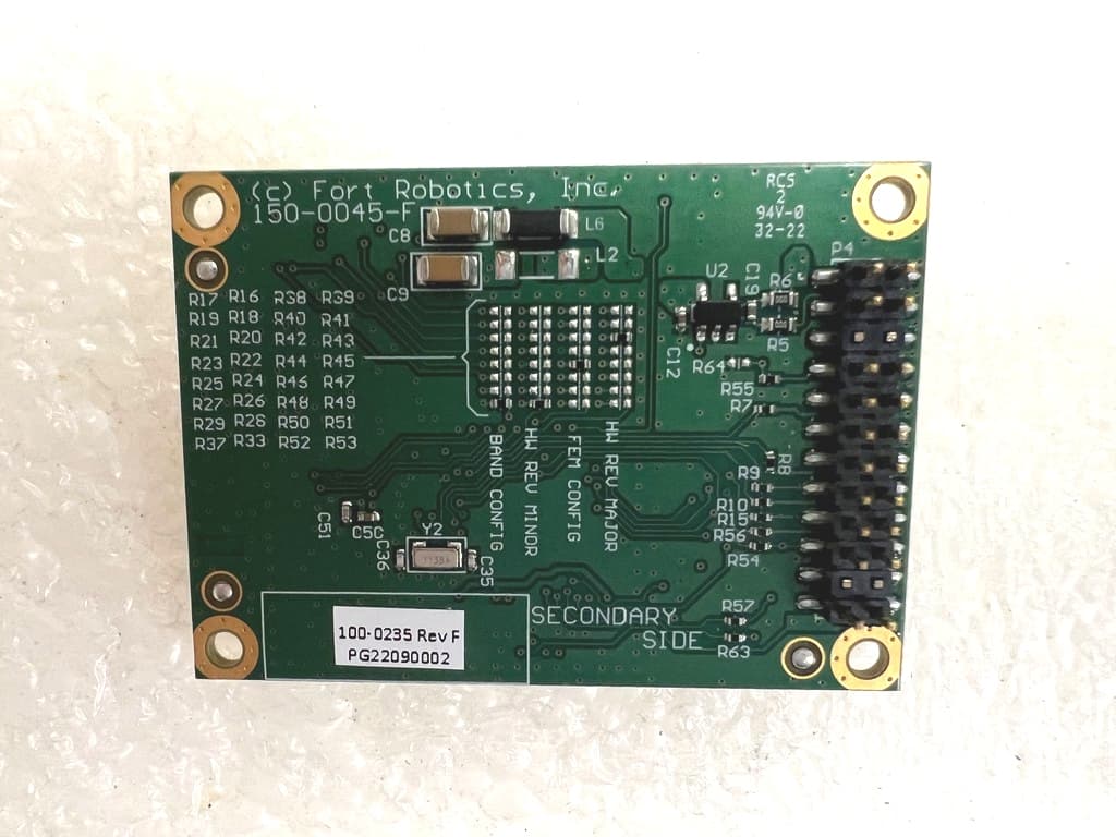
Click to zoom
Application Details
- Equipment Class
- DSS - Part 15 Spread Spectrum Transmitter
- Date of Grant
- Feb 26, 2023
- Application Purpose
- Original Equipment
- Date of Application
- Feb 26, 2023
- Equipment Note
- ISM Radio Module 100-0235
- Frequency Range
- 902.60000000 - 927.40000000
- Company
- Fort Robotics Inc.
- Country
- United States
Documents & Files
Document Text
Text extracted from the exhibit documents filed with the FCC. Open a document above to read the original.
Users Manual
Features ISM Radio Bands 902 - 928 MHz Geography North America, Brazil, Argentina Manual link to draft manual Device Form Factor mountable embedded module Dimensions 36mm x 50mm Base Unit Weight 9g Operating Temps -40°C to +85°C Operating Voltage 3.3 V Operating Current 500mA (max) ISM Range 1 km LOS (testing pending) Output Radio Transmission Power 23 dBm Protocols proprietary TDMA protocol (single Master multi Slave RF communication protocol) Connectors 24 pin integration connector Serial Baud Rate 460.8 kHz maximum Power Draw 1.65 W Channels 24 Moduation 2-GFSK Regulatory Approval FCC, IC Recommended Antenna Linx Technologies ANT-916-CW-QW FPN: 275-0080 Antenna Connector u.FL FORT Product Compatibility Endpoint Controller ✔ Safe Remote Control Pro ✔ Nano Safety Controller ✔ 267-515-5880 | fortrobotics.com FCC Statement The FORT ISM Radio has received Federal Communications Commission (FCC) CFR47 Telecommunications, Part 15 Subpart C “Intentional Radiators” modular approval in accordance with Part 15.247 Modular Transmitter approval. The modular approval allows the end user to integrate the module into a finished product without obtaining subsequent and separate FCC approvals for intentional radiation, provided no changes or modifications are made to the module circuitry. Changes or modifications could void the user’s authority to operate the equipment. The end user must comply with all of the instructions provided by the Grantee, FORT Robotics, which indicate installation and/or operating conditions necessary for compliance. The finished product is required to comply with all applicable FCC equipment authorizations, regulations, requirements and equipment functions not associated with the transmitter module portion. For example, compliance must be demonstrated to regulations for other transmitter components within the host product; to requirements for unintentional radiators (Part 15 Subpart B “Unintentional Radiators”), such as digital devices, computer peripherals, radio receivers, etc.; and to additional authorization requirements for the non-transmitter functions on the transmitter module (i.e., Verification, or Declaration of Conformity) (e.g., transmitter modules may also contain digital logic functions) as appropriate. Modification to this product will void the users’ authority to operate this equipment. The OEM is still responsible for verifying end product compliance with FCC Part 15, subpart B limits for unintentional radiators through an accredited test facility. This device complies with part 15 of the FCC Rules. Operation is subject to the following two conditions: (1) This device may not cause harmful interference, and (2) this device must accept any interference received, including interference that may cause undesired operation. Note: This equipment has been tested and found to comply with the limits for a Class A digital device, pursuant to part 15 of the FCC Rules. These limits are designed to provide reasonable protection against harmful interference when the equipment is operated in a commercial environment. This equipment generates, uses, and can radiate radio frequency energy and, if not installed and used in accordance with the instruction manual, may cause harmful interference to radio communications. Operation of this equipment in a residential area is likely to cause harmful interference in which case the user will be required to correct the interference at his own expense. 267-515-5880 | fortrobotics.com FCC ID Labeling The FORT ISM Radio is assigned the FCC ID number: 2A8I8-100235 If the FCC ID is not visible when the module is installed inside another device, then the outside of the finished product into which the module is installed must also display a label referring to the enclosed module. This exterior label can use the following or similar wording: Contains FCC ID: 2A8I8-100235 In addition to marking the product with the appropriate FCC ID, the end product user manual may also require specific information based on the digital device classification. Refer to the FCC Rules, Title 47, Subchapter A, Part 15, Subpart B, Chapter §15.105 for specific wording of the notices. FCC RF Exposure Requirements All transmit ters regulated by FCC must comply with RF exposure requirements. KDB 447498 General RF Exposure Guidance provides direction in determining whether proposed or existing transmitting facilities, operations, or devices comply with limits for human exposure to Radio Frequency (RF) fields adopted by the Federal Communications Commission (FCC). This module is approved for installation into mobile and/or portable host platforms and must not be co-located or operating in conjunction with any other antenna or transmitter except in accordance with FCC multi-transmitter guidelines. End users must be provided with transmitter operating conditions for satisfying RF Exposure compliance. This module may be used for mobile or portable applications. In order to meet RF exposure requirements, a 20cm separation distance is required for mobile applications and a 3cm separation distance from extremity to antenna is required for portable applications. The end product manufacturer or integrator shall be responsible for final RF safety conformity. IC Statement The FORT ISM Radio module is certified for use in Canada under Innovation, Science and Economic Development Canada (ISED) Radio Standards Specification (RSS) RSS-247 and RSSGen. 267-515-5880 |fortrobotics.com IC ID Labeling The FORT ISM Radio is assigned the IC ID number: 29381-100235 The host device shall be properly labeled to identify the module within the host device. The Industry Canada certification label of a module shall be clearly visible at all times when installed in the host device, otherwise the host device must be labeled to display the Industry Canada certification number of the module, preceded by the words “Contains transmitter module”, or the word “Contains”, or similar wording expressing the same…
Text truncated - open the document above for the full version.
External Photos
EUT: ISM Radio Module Report No: 0048-221212-01-FCC-IC Model: 100-0235 FCC ID: 2A8I8-100235 IC: 29381-100235 Page 37 of 39 Advanced Compliance Laboratory, Inc. 210 Cougar Court, Hillsborough, NJ 08844, tel:(908) 927 9288 PRODUCT PHOTOS EUT/ RF Module PCB Primary Side EUT: ISM Radio Module Report No: 0048-221212-01-FCC-IC Model: 100-0235 FCC ID: 2A8I8-100235 IC: 29381-100235 Page 38 of 39 Advanced Compliance Laboratory, Inc. 210 Cougar Court, Hillsborough, NJ 08844, tel:(908) 927 9288 EUT/ RF Module PCB Secondary Side
ID Label/Location Info
EUT: ISM Radio Module Report No: 0048-221212-01-FCC-IC Model: 100-0235 FCC ID: 2A8I8-100235 IC: 29381-100235 Page 36 of 39 Advanced Compliance Laboratory, Inc. 210 Cougar Court, Hillsborough, NJ 08844, tel:(908) 927 9288 FCC Label for RF module: ISM Radio 100-0235 Host Device ID Label Fort Robotics ISM Radio Model/Part: 100-0235 FCC ID: 2A8I8-100235 IC: 29381-100235 This device complies with FCC Part 15C & ISED Rules. Operating is subject to the following two conditions: (1) This device may not cause harmful interference, and (2) this device must accept any interference received, including interference that may cause undesired operation. FCC Caution: Any changes or modifications not expressly approved by the party responsible for compliance could void the user's authority to operate this equipment. Proposed FCC ID Label for RF Module (The statement may be shown in its user manual for small size device ) ID Label Product Name Model Number Contains FCC ID: 2A8I8-100235 IC: 29381-100235 This device complies with FCC Part 15C Rules. Operating is subject to the following two conditions: (1) This device may not cause harmful interference, and (2) this device must accept any interference received, including interference that may cause undesired operation. FCC Caution: Any changes or modifications not expressly approved by the party responsible for compliance could void the user's authority to operate this equipment.
Internal Photos
EUT: ISM Radio Module Report No: 0048-221212-01-FCC-IC Model: 100-0235 FCC ID: 2A8I8-100235 IC: 29381-100235 Page 39 of 39 Advanced Compliance Laboratory, Inc. 210 Cougar Court, Hillsborough, NJ 08844, tel:(908) 927 9288 EUT/ RF Module with shielding cover removed
RF Exposure Info
EUT: ISM Radio Module Report No: 0048-221212-01-FCC-IC Model: 100-0235 FCC ID: 2A8I8-100235 IC: 29381-100235 Page 17 of 41 Advanced Compliance Laboratory, Inc. 210 Cougar Court, Hillsborough, NJ 08844, tel:(908) 927 9288 7.3 MAXIMUM PERMISSIBLE EXPOSURE LIMITS for FCC RF Exposure Evaluation §1.1310 The criteria listed in Table 1 shall be used to evaluate the environmental impact of human exposure to radio-frequency (RF) radiation as sp ecified in §1.1307(b), except in the case of portable devices which shall be evaluated according to the provisions of §2.1093 of this chapter. LIMITS for FCC SAR Evaluation KDB 447498 D04 Interim General RF Exposure Guidance v01, section 2.1.3 SAR-Based Exemption: “A more comprehensive exemption, considering a variable power threshold that depends on both the separation distance and power, is provided in § 1.1307(b)(3)(i)(B). This exemption is applicable to the frequency range between 300 MHz and 6 GHz, with test separation distances between 0.5 cm and 40 cm, and for all RF sources in fixed, mobile, and portable device exposure conditions.” For 100 MHz to 6 GHz and test separation distances ≤ 50 mm, the 1-g and 10-g SAR test exclusion thresholds are determined by the following: [(max. power of channel, including tune-up tolerance, mW) / (min. test separation distance, mm)] · [√f(GHz)] ≤ 3.0 for 1-g SAR, and ≤ 7.5 for 10-g extremity SAR, where f(GHz) is the RF channel transmit frequency in GHz EUT: ISM Radio Module Report No: 0048-221212-01-FCC-IC Model: 100-0235 FCC ID: 2A8I8-100235 IC: 29381-100235 Page 18 of 41 Advanced Compliance Laboratory, Inc. 210 Cougar Court, Hillsborough, NJ 08844, tel:(908) 927 9288 FCC KDB 447498 D01 General RF Exposure Guidance v06, section 4.3.1 & Appendix A provides the SAR Test Exclusion Thresholds (ERP/Condcuted) to verify that the device is exempt from 1-g extremity SAR at different separation distances. As example, for 900MHz Tx: 16mW (12dBm); For 2450MHz Tx: 10mW (10dBm) at ≤5 mm. Details in calculation formula for reference, given in § 1.1307(b)(3)(i)(B) to calculate the exemption: EUT: ISM Radio Module Report No: 0048-221212-01-FCC-IC Model: 100-0235 FCC ID: 2A8I8-100235 IC: 29381-100235 Page 19 of 41 Advanced Compliance Laboratory, Inc. 210 Cougar Court, Hillsborough, NJ 08844, tel:(908) 927 9288 LIMITS per ISED RSS-102, Section 2.5 & Table 1 Per 2.5.1 Exemption Limits for Routine Evaluation — SAR Evaluation For limb-worn devices where the 10 gram value applies, the exemption limits for routine evaluation in Table 1 are multiplied by a factor of 2.5. Example: Exclusion Thresholds to verify that the device is exempt from 1-g SAR at separation distance of ≤5 mm: For 900MHz Tx: 16mW (12dBm); For 2450MHz Tx: 4mW (6dBm). Per 2.5.2 Exemption Limits for Routine Evaluation – RF Exposure Evaluation RF exposure evaluation is required if the separation distance between the user and/or bystander and the device’s radiating element is greater than 20 cm, except when the device operates as follows: • below 20 MHz and the source-based, time-averaged maximum e.i.r.p. of the device is equal to or less than 1 W (adjusted for tune-up tolerance); • at or above 20 MHz and below 48 MHz and the source-based, time-averaged maximum e.i.r.p. of the device is equal to or less than 4.49/f 0.5 W (adjusted for tune-up tolerance), where ƒ is in MHz; • at or above 48 MHz and below 300 MHz and the source-based, time-averaged maximum e.i.r.p. of the device is equal to or less than 0.6 W (adjusted for tune-up tolerance); • at or above 300 MHz and below 6 GHz and the source-based, time-averaged maximum e.i.r.p. of the device is equal to or less than 1.31 x 10 -2 ƒ 0.6834 W (adjusted for tune-up tolerance), where ƒ is in MHz; • at or above 6 GHz and the source-based, time-averaged maximum e.i.r.p. of the device is equal to or less than 5 W (adjusted for tune-up tolerance). In these cases, the information contained in the RF exposure technical brief may be limited to information that demonstrates how the e.i.r.p. was derived. Summary For FCC and IC, that max. declared power level can be modified by any duty cycle over the time averaging period. Time-averaging period is a time period not to exceed 30 minutes for fixed RF sources or a time period inherent from device transmission characteristics not to exceed 30 minutes for mobile and portable RF sources. For rf exposure, the averaging period is 6 minutes for ISED Canada and for FCC it varies by frequency but 1~60 second for RF exposure or the period specified by product design spec. for RF exposure can be used. So the power value for RF exposure= Declared power x Duty Cycle factor EUT: ISM Radio Module Report No: 0048-221212-01-FCC-IC Model: 100-0235 FCC ID: 2A8I8-100235 IC: 29381-100235 Page 20 of 41 Advanced Compliance Laboratory, Inc. 210 Cougar Court, Hillsborough, NJ 08844, tel:(908) 927 9288 CALCULATIONS for MPE distance and Power Density Given E = √ (30 * P * G) / d and S = E ^ 2 / 3770 where E = Field Strength in Volts/meter P = Power in Watts G = Numeric antenna gain d = Distance in meters S = Power Density in milliwatts/square centimeter Combining equations and rearranging the terms to express the distance as a function of the remaining variables yields: d = √ ((30 * P * G) / (3770 * S)) Changing to units of Power to mW and Distance to cm, using: P(mW) = P (W) / 1000 and d (cm) =100 * d (m) yields d = 100 * √ ((30 * (P / 1000) * G) / (3770 * S)) d = 0.282 * √ (P * G / S) where d = distance in cm P = Power in mW G = Numeric antenna gain S = Power Density in mW/cm^2 Substituting the logarithmic form of power and gain using: P (mW) = 10 ^ (P (dBm) / 10) and G (numeric) = 10 ^ (G (dBi) / 10) yi elds d = 0.282 * 10 ^ ((P + G) / 20) / √ S Equation (1) S = 0.0795 * 10 ^ ((P + G)/10)/ d^2 Equation (2) where d = MPE distance in cm P = Power in dBm G = Antenna Gain in dBi S = Power Density Limit in mW/cm^2 Equation (1) and the measured Output power is used to calculate the MPE distance. Equation (2) and the…
Text truncated - open the document above for the full version.
Test Report
EUT: ISM Radio Module Report No: 0048-221212-01-FCC-IC Model: 100-0235 FCC ID: 2A8I8-100235 IC: 29381-100235 Page 1 of 39 Advanced Compliance Laboratory, Inc. 210 Cougar Court, Hillsborough, NJ 08844, tel:(908) 927 9288 FCC CFR47 PART 15 SUBPART C & IC RSS-247 TEST REPORT For Ford Robotics, Inc. ISM RADIO MODULE Model Number: 100-0235 FCC ID: 2A8I8-100235 IC: 29381-100235 Report Number: 0048-221212-01-FCC Prepared for FORD ROBOTICS, INC. 1608 Walnut Street Philadelphia, PA 19103 USA Prepared by Advanced Compliance Laboratory, Inc. 210 Cougar Court Hillsborough, NJ 08844 Tel: (908) 927 9288 Fax: (908) 927 0728 Date: 12/20/2022 210 Cougar Court Hillsborough, NJ 08844 Tel: (908) 927 9288 Fax: (908) 927 0728 Advanced Compliance Laboratory EUT: ISM Radio Module Report No: 0048-221212-01-FCC-IC Model: 100-0235 FCC ID: 2A8I8-100235 IC: 29381-100235 Page 2 of 39 Advanced Compliance Laboratory, Inc. 210 Cougar Court, Hillsborough, NJ 08844, tel:(908) 927 9288 TABLE OF CONTENTS 1. TEST RESULT CERTIFICATION ............................................................................................ 3 2. EUT DESCRIPTION .................................................................................................................. 4 3. TEST METHODOLOGY ........................................................................................................... 5 4. FACILITIES AND ACCREDITATION .................................................................................... 5 5. CALIBRATION AND UNCERTAINTY ................................................................................... 6 5.1. MEASURING INSTRUMENT CALIBRATION ............................................................. 6 5.2. MEASUREMENT UNCERTAINTY ................................................................................ 6 5.3. TEST AND MEASUREMENT EQUIPMENT ................................................................. 7 6. SETUP OF EQUIPMENT UNDER TEST ................................................................................. 8 7. APPLICABLE LIMITS AND TEST RESULTS ........................................................................ 9 7.1 6dB &99% BANDWIDTH ................................................................................................ 9 7.2 PEAK OUTPUT POWER ................................................................................................. 12 7.3 MAXIMUM PERMISSIBLE EXPOSURE ...................................................................... 16 7.4 AVERAGE POWER ......................................................................................................... 20 7.5 PEAK POWER SPECTRAL DENSITY .......................................................................... 21 7.6 CONDUCTED SPURIOUS EMISSIONS ........................................................................ 24 7.7 RADIATED EMISSIONS ................................................................................................ 28 7.7.1. TRANSMITTER RADIATED SPURIOUS EMISSIONS ........................................ 28 7.7.2. TRANSMITTER RADIATED EMISSIONS DATA ................................................ 30 8. SETUP PHOTOS ...................................................................................................................... 32 9. APPENDIX ............................................................................................................................... 35 EUT: ISM Radio Module Report No: 0048-221212-01-FCC-IC Model: 100-0235 FCC ID: 2A8I8-100235 IC: 29381-100235 Page 3 of 39 Advanced Compliance Laboratory, Inc. 210 Cougar Court, Hillsborough, NJ 08844, tel:(908) 927 9288 1. TEST RESULT CERTIFICATION COMPANY NAME: FORD ROBOTICS EUT DESCRIPTION: ISM Radio Module MODEL: 100-0235 DATE TESTED: 12/12/2022 to 12/20/2022 APPLICABLE STANDARDS STANDARD TEST RESULTS FCC Part 15.247 & ISED RSS-247 ( Issue 2) NO NON-COMPLIANCE NOTED Advanced Compliance Laboratory, Inc. tested the above equipment in accordance with the requirements set forth in the above standards. The test results show that the equipment tested is capable of demonstrating compliance with the requirements as documented in this report. Note : This document reports conditions under which testing was conducted and results of tests performed. This document may not be altered or revised in any way unless done so by Advanced Compliance Laboratory, Inc. (ACL) and all revisions are duly noted in the revisions section. Any alteration of this document not carried out by ACL, Advanced Compliance Laboratory, Inc. will constitute fraud and shall nullify the document. Approved & Released For ACL By: Tested By: Wei Li Edward Lee Manager EMC Engineer Advanced Compliance Laboratory, Inc. EUT: ISM Radio Module Report No: 0048-221212-01-FCC-IC Model: 100-0235 FCC ID: 2A8I8-100235 IC: 29381-100235 Page 4 of 39 Advanced Compliance Laboratory, Inc. 210 Cougar Court, Hillsborough, NJ 08844, tel:(908) 927 9288 2. EUT DESCRIPTION The EUT for this certification is a low power transmitter, using digital modulation & operating in the 900 MHz band. The transmitter has a maximum peak conducted output power as follows: Frequency /Range (MHz) Rated Power Selection Tested Power (dBm/W)* 902.6-927.4 24.25dBm/0.266W 24.32/0.270W Antenna Information: Antenna Type Manufacturer Model Number Operating Band (MHz) Max. Gain (dBi) 1/4-Wave Compact Antenna /Omni-directional (RP-SMA) Linx ANT-916-CW-QW 865-965 1.8 All external antenna has reverse polarity SMA connector, which will be connected to the RF module via 8” cable with matching RSMA connector. EUT: ISM Radio Module Report No: 0048-221212-01-FCC-IC Model: 100-0235 FCC ID: 2A8I8-100235 IC: 29381-100235 Page 5 of 39 Advanced Compliance Laboratory, Inc. 210 Cougar Court, Hillsborough, NJ 08844, tel:(908) 927 9288 3. TEST METHODOLOGY The tests documented in this report were performed in accordance with ANSI C63.4-2014/C63.10-2013, FCC CFR 47 Part 2 & 15 and IC RSS-247 issue 1 & RSS-Gen issue 4. Te…
Text truncated - open the document above for the full version.
Test Report
–1 – Revised 12/9/13 Product Description CW Series ¼-wave antennas deliver outstanding performance in a rugged and cosmetically attractive package. These antennas are available with standard SMA or FCC Part 15 compliant RP-SMA connectors. RP-SMA connectors allow for easy field replacement while complying with FCC requirements. A wide variety of matching connectors permit numerous mounting options. Features •Low cost •Excellent performance •Omni-directional pattern •Wide bandwidth •Very low VSWR •Fully weatherized •Flexible main shaft •Rugged & damage-resistant •SMA or Part 15 compliant RP-SMA connector •Use with plastic* or metal enclosures *Requires proximity ground plane Electrical Specifications Center Frequency: 916MHz Recom. Freq. Range: 865–965MHz Wavelength:¼-wave Peak Gain: 1.8dBi VSWR: <1.9 typ. at center Impedance:50-ohms Connector: RP-SMA or SMA Oper. Temp. Range: –40°C to +90°C Electrical specifications and plots measured on 10.16 cm x 10.16 cm (4.00” x 4.00”) reference ground plane ANT-916-CW-QW Data Sheet by Ordering Information ANT-916-CW-QW (with RP-SMA connector) ANT-916-CW-QW-SMA (with SMA connector) 14.5 mm (0.57") 13.0 mm (0.51") 80.0 mm (3.15") 52.0 mm (2.05") 6.0 mm (0.24") 6.4 mm (0.25") End View 7.8 mm (0.31") 4.5 mm (0.18") FORT pn: 275-0080 / MFG pn: ANT-916-CW-QW / by: mkorejwo 19MAY2021 – 2 – Counterpoise Quarter-wave or monopole antennas require an associated ground plane counterpoise for proper operation. The size and location of the ground plate relative to the antenna will affect the overall performance of the antenna in the final design. When used in conjunction with a ground plane smaller than that used to tune the antenna, the center frequency typically will shift higher in frequency and the bandwidth will decrease. The proximity of other circuit elements and packaging near the antenna will also affect the final performance. For further discussion and guidance on the importance of the ground plane counterpoise, please refer to Linx Application Note AN-00501: Understanding Antenna Specifications and Operation. by Data Sheet ANT-916-CW-QW VSWRReflected Power 3:1 2:1 1:1 25% 11% 0% 916MHz1016MHz816MHz 1.660 VSWR Graph What is VSWR? The Voltage Standing Wave Ratio (VSWR) is a measurement of how well an antenna is matched to a source impedance, typically 50-ohms. It is calculated by measuring the voltage wave that is headed toward the load versus the voltage wave that is reflected back from the load. A perfect match will have a VSWR of 1:1. The higher the first number, the worse the match, and the more inefficient the system. Since a perfect match cannot ever be obtained, some benchmark for performance needs to be set. In the case of antenna VSWR, this is usually 2:1. At this point, 88.9% of the energy sent to the antenna by the transmitter is radiated into free space and 11.1% is either reflected back into the source or lost as heat on the structure of the antenna. In the other direction, 88.9% of the energy recovered by the antenna is transferred into the receiver. As a side note, since the “:1” is always implied, many data sheets will remove it and just display the first number. How to Read a VSWR Graph VSWR is usually displayed graphically versus frequency. The lowest point on the graph is the antenna’s operational center frequency. In most cases, this will be different than the designed center frequency due to fabrication tolerances. The VSWR at that point denotes how close to 50-ohms the antenna gets. Linx specifies the recommended bandwidth as the range where the typical antenna VSWR is less than 2:1. 159 Ort Lane, Merlin, OR, US 97532 Phone: +1 541 471 6256 Fax: +1 541 471 6251 www.linxtechnologies.com
Test Setup Photos
EUT: ISM Radio Module Report No: 0048-221212-01-FCC-IC Model: 100-0235 FCC ID: 2A8I8-100235 IC: 29381-100235 Page 32 of 39 Advanced Compliance Laboratory, Inc. 210 Cougar Court, Hillsborough, NJ 08844, tel:(908) 927 9288 8. SETUP PHOTOS Conducted Measurements at Antenna Port EUT: ISM Radio Module Report No: 0048-221212-01-FCC-IC Model: 100-0235 FCC ID: 2A8I8-100235 IC: 29381-100235 Page 33 of 39 Advanced Compliance Laboratory, Inc. 210 Cougar Court, Hillsborough, NJ 08844, tel:(908) 927 9288 Field Strength of Spurious EUT: ISM Radio Module Report No: 0048-221212-01-FCC-IC Model: 100-0235 FCC ID: 2A8I8-100235 IC: 29381-100235 Page 34 of 39 Advanced Compliance Laboratory, Inc. 210 Cougar Court, Hillsborough, NJ 08844, tel:(908) 927 9288
Contact Information
Applicant
Eric Zaremski
Test Firm
Advanced Compliance Laboratory, Inc.Wei Li
Technical Specifications
| # | Rule Parts | Frequency Range | Power Output |
|---|---|---|---|
| 1 | 15C | 902.6 MHz - 927.4 MHz | 270.00 mW |
Other Applications from Fort Robotics Inc.

2A8I8-1000415
Dec 18, 2025Wireless E-Stop Pro
Equipment Class
DTS - Digital Transmission System2A8I8-1000308-1
Nov 18, 2025Safe Remote Control Pro
Equipment Class
DTS - Digital Transmission System