FCCID.CO- FCC ID Database
HomeCompaniesEquipment ClassesSearch

© 2026 FCC ID Database. All rights reserved.

AboutContactData sourced from FCC public records
  1. Home/
  2. Forcite Helmet Systems Pty Ltd/
  3. 2A8MD-MK1

2A8MD-MK1FORCITE HELMET with WiFi and Bluetooth

Forcite Helmet Systems Pty Ltd
FORCITE HELMET with WiFi and Bluetooth - FCC ID 2A8MD-MK1 - Forcite Helmet Systems Pty Ltd
Click to zoom

Application Details

Equipment Class
DSS - Part 15 Spread Spectrum Transmitter
Date of Grant
Jan 10, 2023
Application Purpose
Original Equipment
Date of Application
Jan 10, 2023
Equipment Note
FORCITE HELMET with WiFi and Bluetooth
Frequency Range
2402.00000000 - 2480.00000000
Company
Forcite Helmet Systems Pty Ltd
Country
Australia

Documents & Files

Select a file to view
Users Manual

↗

Cover Letter(s)

↗
↗
↗
↗

External Photos

↗

ID Label/Location Info

↗

Internal Photos

↗

RF Exposure Info

↗

Test Report

↗
↗

Test Setup Photos

↗
↗

Document Text

Text extracted from the exhibit documents filed with the FCC. Open a document above to read the original.

Users Manual

1 1 THE NEXT GENERATION HELMET HELMET 2 PRE-RIDE CHECKLIST For further questions, please contact [email protected] Forcite recommends class 10 SD cards CHECK YOUR SD CARD IS INSERTED INSTALL THE FORCITE APP Please use a 5V 2A charger ENSURE YOUR HELMET IS CHARGED 01 02 03 CONTENTS 3 MK1S FEATURES 4 MK1S HELMET 5 HELMET MODULE 6 ACCESS PORT COVERS 7 HELMET ALERTS 8 VISOR REMOVAL 10 VISOR INSTALLATION 11 INTERNAL VISOR REMOVAL 12 INTERNAL VISOR INSTALLATION 13 CONTROLLER 14 HANDLE BAR MOUNT 15 MEDIA CABLE 16 MEDIA ON IPHONE 17 HELMET CARE 18 SAFETY AND CUSTOMER SUPPORT 19 FORCITE POLICY 20 WARNINGS 26 4 MK1S FEATURES A full version of this guide is available for download along with information on new features at support.forcitehelmets.com CAMERA SYSTEM (HD 1080 60FPS) BLUETOOTH (5.0) PERIPHERAL LED DISPLAY NAVIGATION GUIDANCE AUDIO PROMPTS AND NOTIFICATIONS PLAY AND CONTROL MUSIC TAKE AND MANAGE PHONE CALLS 5 MK1S HELMET 1. Top vent 2. Forehead vent 3. Internal sun visor 4. Visor 5. Breath deflector 6. Camera 7. Rear vent 8. Sun visor switch 9. Visor lock 10. Visor release trigger 11. Chin vents 12. D-loop strap 6 HELMET MODULE VISOR VIEW PORT PERIPHERAL LED DISPLAY INSIDE HELMET VIEW SD CARD CHARGING / DATA CLOSE UP OF PORTS UNDER CHIN CURTAIN SINGLE CLICK POWER ON/OFF HOLD 6 SEC PAIRING MODE HOLD 25 SEC HARD RESET HELMET POWER BUTTON 7 ACCESS PORT COVERS The Forcite helmet and controller each have a rubber access port cover that fits over the charging ports and SD card slot. CAUTION: Ensure you close these ports firmly to protect the electronics from moisture and dust. If you do not securely close the covers, damage will not be covered by your warranty. 8 HELMET ALERTS Road events and navigation instructions are shown on the peripheral display and through audio. Below is a list of the primary display patterns. To find a list of all the latest Forcite alerts, please visit support.forcitehelmets.com Turn Right GREEN LIGHT Traffic Jam Ahead YELLOW LIGHT Turn Left GREEN LIGHT Road Hazard YELLOW LIGHT Closure / Accident ORANGE LIGHT 9 RED AND BLUE Police Ahead RED LIGHT Still recording Speed Camera RED LIGHT RED LIGHT Recording Started RED LIGHT Recording Stopped 10 VISOR REMOVAL * Before removing the visor, please make sure both sides of the visor lock is in the “OPEN” position. 1. Open the visor to the uppermost position, checking that the tab (A) is above the visor release trigger. 2. Pull up the visor release lever and pull the lower edge of the visor out at the same time. Repeat the same procedure on the other side to remove the visor completely. 11 VISOR INSTALLATION 3 1. Position the visor in its open position over he circular hole on both sides, ensuring the tab (A) is aligned to the visor release trigger 2. Pull the visor release trigger while pushing the visor firmly into place. 3. Release the visor release trigger. 4. Repeat the same procedure on the other side to complete the installation. 12 INTERNAL VISOR R E M O VA L 1. Rotate visor to its fully open position. Flip down the internal sun visor using the sun visor switch on the side of the helmet. 2. Rotate the internal visor down until a small gap is visible, then pull outward firmly to release the sun visor from the mechanism. 13 INTERNAL VISOR INSTALLATION 1. Insert the tabs on the sun visor into the mechanism in the direction of the arrow until the internal visor stops. Repeat on the other side and check it's position. 2. Slide the sun visor switch to retract the internal visor back into the shell while checking for smooth movement. 14 CONTROLLER SINGLE CLICK START/STOP RECORDING PHONE BUTTON CAMERA BUTTON CENTER BUTTON HOLD 6 SEC WIPE SD CARD NAV BUTTON VOLUME UP VOLUME DOWN CANCEL NAVIGATION SINGLE CLICK REPEAT NAVIGATION INSTRUCTION HOLD 2 SEC DOUBLE CLICK SINGLE PRESS ANSWER CALL HOLD 2 SEC SIRI / GOOGLE ASSISTANT HOLD 2 SEC ON /OFF SINGLE CLICK PLAY/PAUSE MUSIC DOUBLE CLICK SKIP TRACK TRIPLE CLICK BACK ONE TRACK HOLD 6 SEC PAIRING MODE REJECT / HANG UP CALL 15 HANDLE BAR MOUNT The Forcite’s handlebar mounting kit comes with two spacers and an additional tightening tool. The mount suits bar sizes ⅞” (22mm), 1" (25mm) and 1-⅛” (28mm). HOW TO MOUNT: 1. Wrap the top and bottom bar mounts around your handle bar and use a spacer to tighten the fit if required. 2. Secure the mounts using the two mount clamp screws provided. 3. Place your controller on top of the top bar mount platform and use the thumb screw to tighten the controller to the handlebar mount. 16 MEDIA CABLE HOW TO ACCESS MEDIA The 1 media manager allows you to view your ride footage, then edit and share it from your phone, by using the media access cable between your phone and helmet. To access the media manager, go to Main Menu > Media Here you will be prompted to connect your media access cable to your mobile device and Forcite helmet. Ensure the middle USB-C is attached to the helmet, and the other USB-C is connected to your Mobile device. PHONE USB-C POWER USB-A HELMET USB-C 17 MEDIA ON IPHONE If you are using an iPhone, you will need to purchase an apple lightning to USB camera adapter which is available in the Apple store. Forcite's media access cable comes with the required USB-A to USB-C adapter. Once your helmet and phone are connected, follow the instructions in the app to access your media. USB-A TO USB-C ADAPTER APPLE LIGHTNING ADAPTER 18 HELMET CARE 1. Only use water or mild detergents to clean the visor or the inner liner of the helmet. 2. Remove the visor and the inner liner before cleaning. 3. Gently wash the inner liner by hand with a clean cloth, then let it dry in a ventilated area. Note: all liners come in different sizes WARNING This product can expose you to chemicals which are known to the state of California to cause birth defects or other reproductive harm. For more information, go to https://www.p65warnings.ca.gov IMPORTANT WARNING REGARDING PRODUCT LIMITATIONS Your new Forcite helmet can protect you in multiple ways when you helmet…

Text truncated - open the document above for the full version.

Cover Letter(s)

www.forcitehelmets.com Forcite HQ, Unit A1, 35-39 Bourke Road Alexandria NSW Australia Tel: +61 433 207 730 (Alfred Boyadgis – CEO) Tel: +61 467 820 620 (Anthony Harris – CFO) ACN: 165 647 183 Date: 22 November 2022 Attestation for FCC Declaration of Conformity FCC ID: 2A8MD-MK1 Data: 2022/11/22 Please be notified that we, the undersigned, Forcite Helmet Systems PTY LTD. declares that the product which bears the above FCC ID is also compliant with the FCC requirements for SDoC. The test report number supporting the SDoC is report No: 220600063THC-001. Testing in regards to this report was done by Intertek Testing Services Taiwan Ltd, located at 11, Ln. 275, Ko Nan 1st St. Shiang-Shan District, Hsinchu 300 Taiwan, which has been accredited in accordance to all of the requirements of 47CFR 2.948 (d) and (e) of the FCC rules and KDB349827. Sincerely, Name: Anthony Harris Company: Forcite Helmet Systems Pty Ltd Address: Unit A1/ 35-39 Bourke Road, Alexandria, NSW 2015, Australia Phone:+61 467 820 620

Cover Letter(s)

www.forcitehelmets.com Forcite HQ, Unit A1, 35-39 Bourke Road Alexandria NSW Australia Tel: +61 433 207 730 (Alfred Boyadgis – CEO) Tel: +61 467 820 620 (Anthony Harris – CFO) ACN: 165 647 183 Authority to Act as Agent Date: 27 September 2022 PHOENIX TESTLAB GmbH Product Certification Königswinkel 10 D 32825 Blomberg To Whom It May Concern: Intertek Testing Services Taiwan Ltd (Rico Deng) is authorized to act on our behalf, until otherwise notified, for applications to PHOENIX TESTLAB GmbH. We certify that we are not subject to denial of federal benefits, that includes FCC benefits, pursuant to Section 5301 of the Anti-Drug Abuse Act of 1988, 21 U.S.C. 862. Further, no party, as defined in 47 CFR 1.2002 (b), to the application is subject to denial of federal benefits, that includes FCC benefits. Thank you, Name: Anthony Harris Company: Forcite Helmet Systems PTY LTD Address: Unit A1/ 35-39 Bourke Road, Alexandria, NSW 2015, Australia Phone: +61 467 820 620

Cover Letter(s)

www.forcitehelmets.com Forcite HQ, Unit A1, 35-39 Bourke Road Alexandria NSW Australia Tel: +61 433 207 730 (Alfred Boyadgis – CEO) Tel: +61 467 820 620 (Anthony Harris – CFO) ACN: 165 647 183 Date: 27 September 2022 To: Federal Communications Commission Office of Engineering and Technology Equipment Authorization Division 7345 Oakland Mills Road Columbia, Maryland 21046 Subject: Confidentiality Request for FCC ID: 2A8MD-MK1 To Whom It May Concern: Pursuant to sections 0.457 and 0.459 of CFR 47, we respectfully request permanent confidential treatment of the following Exhibits accompanying this application as: Block Diagram Schematics Operational Description The above materials contain trade secrets and proprietary information not customarily released to the public. The public disclosure of these materials may be harmful to the applicant and provide unjustified benefits to its competitors. Sincerely, Name: Anthony Harris Company: Forcite Helmet Systems PTY LTD Address: Unit A1/ 35-39 Bourke Road, Alexandria, NSW 2015, Australia Phone: +61 467 820 620

Cover Letter(s)

www.forcit ehelmets.com Forcite HQ, Unit A1, 35-39 Bourke Road Alexandria NSW Australia Tel: +61 433 207 730 (Alfred Boyadgis – CEO) Tel: +61 467 820 620 (Anthony Harris – CFO) ACN: 165 647 183 Date: 27 September 2022 WIFI Channel 12 and 13 Declaration Letter We declare the equipment identified below with regards to Channel 12 and 13 capabilities for FCC ID: 2A8MD-MK1 IC: 29146-MK1 Declaration Product hardware does not have the capability to operate on Channel 12 and 13. Product hardware has the capability to operate on Channel 12 and 13. However, these two channels will be disabled via software and will not be accessible to user. Product hardware has the capability to operate on Channel 12 and 13. However, all the operated channels can’t be changed in the RF parameter via software. All channels have complied with all of the requirements sets out in FCC Part 15.247. Product hardware has the capability to operate on WiFi Channel 12 and 13, and meets the requirements of KDB 594280 D01 v02r01. Please note: 1.) By default, this device operates in a mode that is compliant with the U.S. requirements. 2.) This device will also use supplemental information such as geo-location data to determine that it is operating outside the U.S., if necessary, to change its power. Such supplemental data will be derived from the following: Global Navigation Satellite System (GNSS)7 sensors in the device Mobile Country Code (MCC),8 or MCC with a Mobile Network code (MNC), received from a CMRS9 carrier and received directly by a receiver on the device Country information derived from multiple adjacent access points (for example using IEEE Std 802.11d provisions) may be permitted on case-by-case basis Other suitable geo-location data based on IP addresses or other reliable source. Sincerely, Name: Anthony Harris Company: Forcite Helmet Systems PTY LTD Address: Unit A1/ 35-39 Bourke Road, Alexandria, NSW 2015, Australia Phone: +61 467 820 620

External Photos

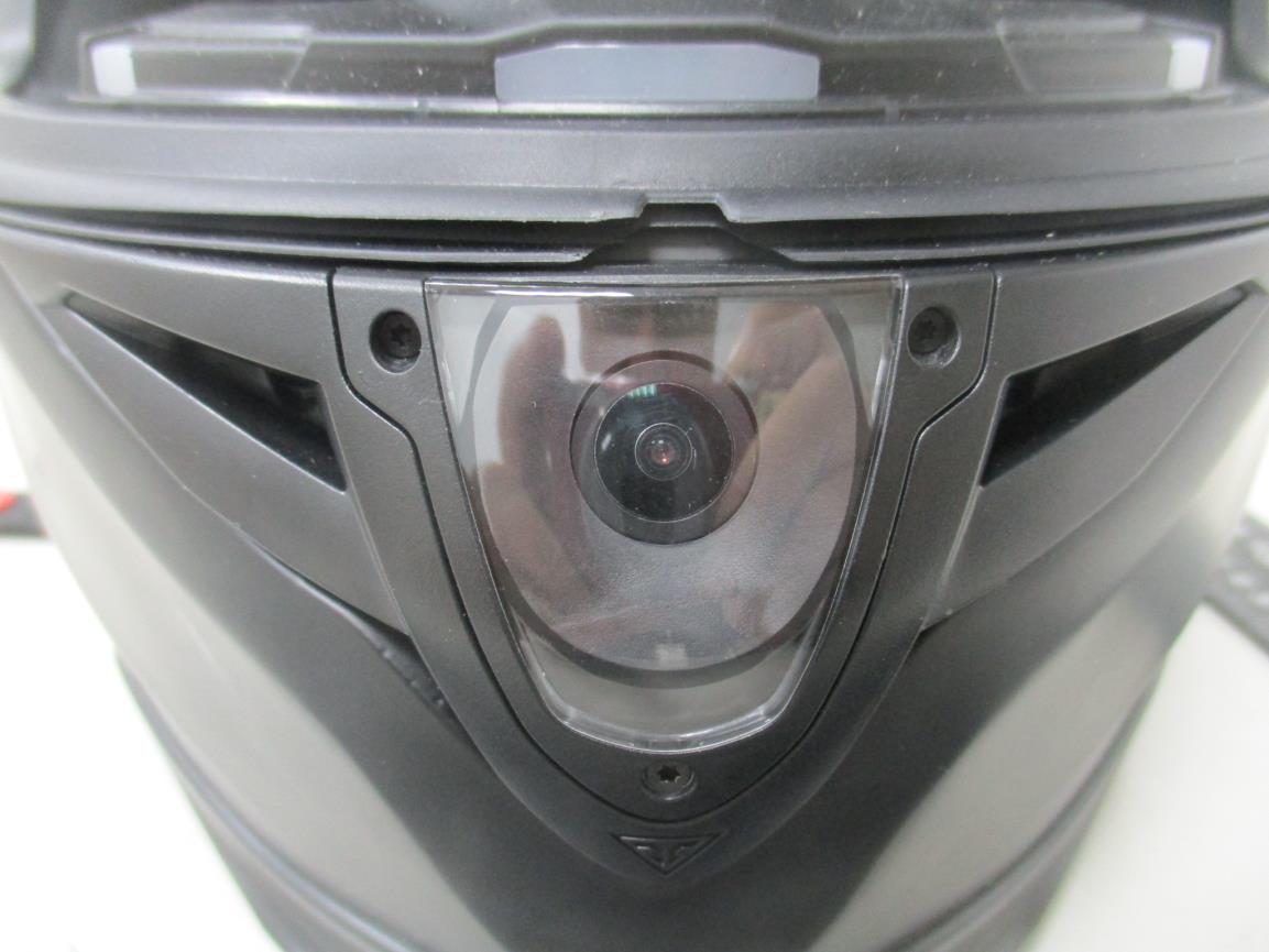
External photo of EUT External photo of EUT External photo of EUT External photo of EUT

Internal Photos

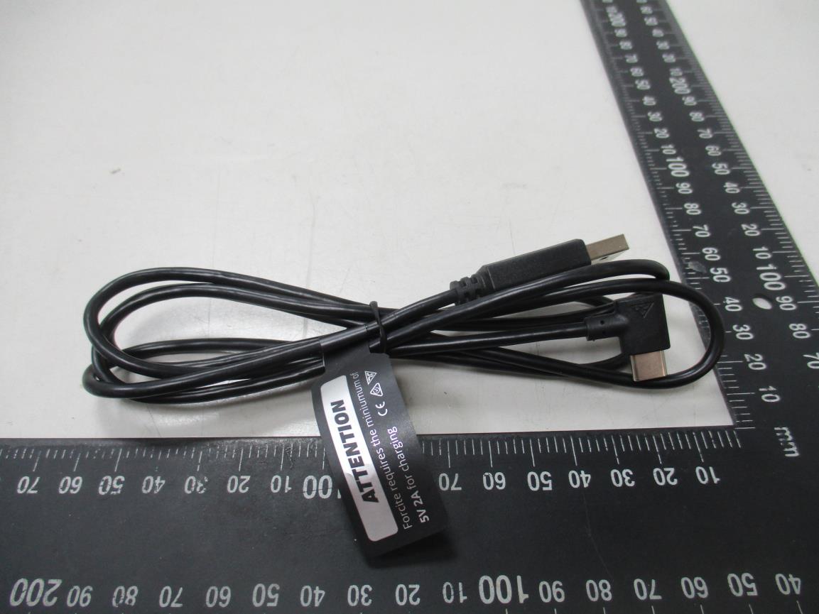
Internal photo of EUT Internal photo of EUT Internal photo of EUT Internal photo of EUT Internal photo of EUT Internal photo of EUT Internal photo of EUT Internal photo of EUT Internal photo of EUT BT Antenna Internal photo of EUT Wi-Fi Antenna Internal photo of EUT BT Module Internal photo of EUT Wi-Fi Module Internal photo of EUT USB Type-C cable

RF Exposure Info

Forcite Helmet Systems PTY LTD TEST REPORT Model: MK1 REPORT NUMBER 220600071THC-001 ISSUE DATE Oct. 17, 2022 PAGES 9 DOCUMENT CONTROL NUMBER GFT-OP-10h (28-Nov-2018) © 2020 Intertek Report No.: 220600071THC-001 This report is for the exclusive use of Intertek's Client and is provided pursuant to the agreement between Intertek and its Client. Intertek's responsibility and liability are limited to the terms and conditions of the agreement. Intertek assumes no liability to any party, other than to the Client in accordance with the agreement, for any loss, expense or damage occasioned by the use of this report. Only the Client is authorized to permit copying or distribution of this report and then only in its entirety. Any use of the Intertek name or one of its marks for the sale or advertisement of the tested material, product or service must first be approved in writing by Intertek. The observations and test results in this report are relevant only to the sample tested. This report by itself does not imply that the material, product, or service is or has ever been under an Intertek certification program. GFT-OP-10h (28-Nov-2018) Page 1 of 9 Test Report Maximum Permissible Exposure (MPE) Evaluation Report Applicant: Forcite Helmet Systems PTY LTD Unit A1, 35-39 Bourke Rd, Alexandria NSW 2015, Australia Product: FORCITE HELMET Model No.: MK1 Brand Name: MK1S, MK1R, MK1X, MK1SE, MK1D FCC ID: 2A8MD-MK1 Test Method/ Standard: 47 CFR FCC 1.1310 KDB 447498 Test By: Intertek Testing Services Taiwan Ltd., Hsinchu Laboratory No. 11, Lane 275, Ko-Nan 1 Street, Chia-Tung Li, Shiang-Shan District, Hsinchu City, Taiwan Zero Chen Engineer Rico Deng Reviewer Report No.: 220600071THC-001 GFT-OP-10h (28-Nov-2018) Page 2 of 9 Revision History Report No. Issue Date Revision Summary 220600071THC-001 Oct. 17, 2022 Original report Report No.: 220600071THC-001 GFT-OP-10h (28-Nov-2018) Page 3 of 9 TEST REPORT Table of Contents 1. General Information ............................................................................................................... 4 1.1 Identification of the EUT .................................................................................................. 4 1.2 Additional information about the EUT ............................................................................. 4 1.3 Antenna description ......................................................................................................... 5 1.4 Peripherals equipment ..................................................................................................... 5 2. Test specifications ................................................................................................................... 6 2.1 RF Exposure calculations .................................................................................................. 6 2.2 Operation mode ............................................................................................................... 6 2.3 Test equipment ................................................................................................................. 6 2.4 Test Set-up ........................................................................................................................ 7 3. Test results .............................................................................................................................. 8 Report No.: 220600071THC-001 GFT-OP-10h (28-Nov-2018) Page 4 of 9 TEST REPORT 1. General Information 1.1 Identification of the EUT Product: FORCITE HELMET Model No.: MK1 Operating Frequency: 1. 2402 MHz ~ 2480 MHz for BLE; BTC 2. 2412 MHz ~ 2462 MHz for Wi-Fi 2.4G Channel Number: 1. 40 channels for BLE 2. 79 channels for BTC 3. 11 channels for Wi-Fi 2.4G Frequency of Each Channel: 1. 2402+2 k, k=0 ~ 39 for BLE 2. 2402+k, k = 0~78 for BTC 3. 2412+5 k, k=0 ~ 10 for Wi-Fi 2.4G Rated Power: DC 5V Power Cord: N/A Sample receiving date: 2022/07/21 Sample condition: Workable Test Date(s): 2022/08/31 1.2 Additional information about the EUT The customer confirmed there are several trade names, the different brands served as marketing strategy. Brand Name Model Number Different MK1S MK1 painting different; helmet padding different MK1R MK1 painting different; helmet padding different MK1X MK1 painting different; helmet padding different MK1SE MK1 painting different; helmet padding different MK1D MK1 painting different; helmet padding different Report No.: 220600071THC-001 GFT-OP-10h (28-Nov-2018) Page 5 of 9 TEST REPORT 1.3 Antenna description For BLE; BTC Antenna Gain : 3.77 dBi Antenna Type : PCB antenna Connector Type : I-Pex For Wi-Fi 2.4G Antenna Gain : 4.2 dBi Antenna Type : PCB antenna Connector Type : I-Pex 1.4 Peripherals equipment Peripherals Brand Model No. Serial No. Data cable Notebook PC ASUS N81V N/A Micro USB shielded cable 0.2m Fixture N/A N/A N/A Micro USB shielded cable 0.2m Adapter Samsung EP-TA10JWS N/A N/A Report No.: 220600071THC-001 GFT-OP-10h (28-Nov-2018) Page 6 of 9 TEST REPORT 2. Test specifications 2.1 RF Exposure calculations According to KDB 447498 D01 , Mobile and Portable Devices RF Exposure Procedures and Equipment Authorization Policies v06. Clause 4.3: General SAR test reduction and exclusion guidance Sub , clause 4.3.1: Standalone SAR test exclusion considerations a) For 100 MHz to 6 GHz and test separation distances > 50 mm, the 1-g and 10-g SAR test exclusion thresholds are determined by the following (also illustrated in Appendix B): 32 1) {[Power allowed at numeric threshold for 50 mm in step a)] + [(test separation distance – 50 mm)·(f(MHz)/150)]} mW, for 100 MHz to 1500 MHz 2) {[Power allowed at numeric threshold for 50 mm in step a)] + [(test separation distance – 50 mm)·10]} mW, for > 1500 MHz and ≤ 6 GHz 2.2 Operation mode For Wi-Fi 2.4G EUT connected to Notebook USB port, executing “tera term” and enter command to select different frequency and modulation. For BLE; BTC Connected to Notebook via USB Cable, ex…

Text truncated - open the document above for the full version.

Test Report

Forcite Helmet Systems PTY LTD TEST REPORT Model: MK1 REPORT NUMBER 220600067THC-001 ISSUE DATE Oct. 17, 2022 PAGES 51 DOCUMENT CONTROL NUMBER GFT-OP-10h (28-Nov-2018) © 2020 Intertek Report No.: 220600067THC-001 This report is for the exclusive use of Intertek's Client and is provided pursuant to the agreement between Intertek and its Client. Intertek's responsibility and liability are limited to the terms and conditions of the agreement. Intertek assumes no liability to any party, other than to the Client in accordance with the agreement, for any loss, expense or damage occasioned by the use of this report. Only the Client is authorized to permit copying or distribution of this report and then only in its entirety. Any use of the Intertek name or one of its marks for the sale or advertisement of the tested material, product or service must first be approved in writing by Intertek. The observations and test results in this report are relevant only to the sample tested. This report by itself does not imply that the material, product, or service is or has ever been under an Intertek certification program. GFT-OP-10h (28-Nov-2018) Page 1 of 51 Test Report 0597 Radio Spectrum TEST REPORT Applicant: Forcite Helmet Systems PTY LTD Unit A1, 35-39 Bourke Rd, Alexandria NSW 2015, Australia Product: FORCITE HELMET Model No.: MK1 Brand Name: MK1S, MK1R, MK1X, MK1SE, MK1D FCC ID: 2A8MD-MK1 Test Method/ Standard: 47 CFR FCC Part 15.247 & ANSI C63.10 2013 KDB 558074 D01 v05r02 Test By: Intertek Testing Services Taiwan Ltd., Hsinchu Laboratory No. 11, Lane 275, Ko-Nan 1 Street, Chia-Tung Li, Shiang-Shan District, Hsinchu City, Taiwan Zero Chen Engineer Rico Deng Reviewer Report No.: 220600067THC-001 GFT-OP-10h (28-Nov-2018) Page 2 of 51 TEST REPORT Revision History Report No. Issue Date Revision Summary 220600067THC-001 Oct. 17, 2022 Original report Report No.: 220600067THC-001 GFT-OP-10h (28-Nov-2018) Page 3 of 51 TEST REPORT Table of Contents Summary of Test Data ................................................................................................................ 5 1. General Information ............................................................................................................... 6 1.1 mIdentification of the EUT ............................................................................................... 6 1.2 Additional information about the EUT ............................................................................. 6 1.3 Antenna description ......................................................................................................... 6 1.4 Operation mode ............................................................................................................... 7 1.5 Peripherals equipment ..................................................................................................... 7 2. 20dB Bandwidth Test .............................................................................................................. 8 2.1 Test Setup & Procedure .................................................................................................... 8 2.2 Operating Environment Condition ................................................................................... 8 2.3 Test Results ....................................................................................................................... 8 3. Carrier Frequency Separation Test ....................................................................................... 12 3.1 Test Setup & Procedure .................................................................................................. 12 3.2 Operating Environment Condition ................................................................................. 12 3.3 Test Results ..................................................................................................................... 12 4. Number of Hopping Frequencies Test .................................................................................. 16 4.1 Test Setup & Procedure .................................................................................................. 16 4.2 Operating Environment Condition ................................................................................. 16 4.3 Test Results ..................................................................................................................... 16 5. Time of Occupancy (Dwell Time) .......................................................................................... 18 5.1 Test Setup & Procedure .................................................................................................. 18 5.2 Operating Environment Condition ................................................................................. 18 5.3 Test Results ..................................................................................................................... 18 6. Maximum Output Power Test .............................................................................................. 22 6.1 Test Setup & Procedure .................................................................................................. 22 6.2 Operating Environment Condition ................................................................................. 22 6.3 Test Results ..................................................................................................................... 22 7. RF Antenna Conducted Spurious Test .................................................................................. 23 7.1 Test Setup & Procedure .................................................................................................. 23 7.2 Operating Environment Condition ................................................................................. 23 7.3 Test Results ..................................................................................................................... 24 8. Emissions in Res…

Text truncated - open the document above for the full version.

Test Setup Photos

Conducted Emission Test set-up photo

Test Setup Photos

Radiated Emission Test set-up photo 9kHz~30MHz Radiated Emission Test set-up photo 30MHz~1GHz Radiated Emission Test set-up photo Above 1GHz

Contact Information

Applicant

Anthony D Harris(Chief Financial Officer)
[email protected]0467820620Fax: n/a

Test Firm

Intertek Testing Services Taiwan LtdTed Wu
[email protected]+886-2-66022888Fax: +886-3-327-0978

Technical Specifications

#Rule PartsFrequency RangePower Output
115C2.40 GHz - 2.48 GHz840.00 µW
Confidentiality
Long Term
Grant Notes
Output power is maximum average conducted.<br> This device has integrated DSS and DTS transmitters certified under the same FCC ID.

Other Applications from Forcite Helmet Systems Pty Ltd

FORCITE BT CONTROLLER MK01 with Bluetooth - FCC ID 2A8MD-MK1HBC - Forcite Helmet Systems Pty Ltd
2A8MD-MK1HBC

FORCITE BT CONTROLLER MK01 with Bluetooth

Jan 08, 2023

Equipment Class

DTS - Digital Transmission System