2A8PC-EL00Ce-LOOP
Microtech Designs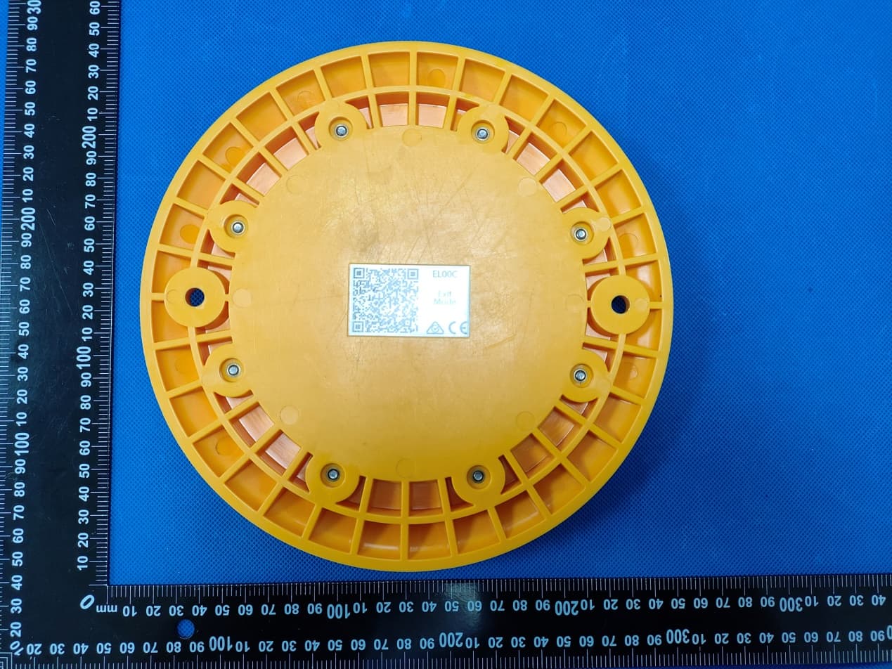
Click to zoom
Application Details
- Equipment Class
- DSC - Part 15 Security/Remote Control Transmitter
- Date of Grant
- Oct 15, 2023
- Application Purpose
- Original Equipment
- Date of Application
- Oct 15, 2023
- Equipment Note
- e-LOOP
- Frequency Range
- 433.39000000 - 433.39000000
- Company
- Microtech Designs
- Country
- Australia
Documents & Files
Document Text
Text extracted from the exhibit documents filed with the FCC. Open a document above to read the original.
Users Manual
Speci fications Frequency: Security: Range: Batterylife: 433.39MHz 128-bitAESencry ption up to 50 metres up to 10 years Batterytype:Lithium ion 3.6V2700 mA x 4 e-LOOPFittingInstructions Step1-Codinge-LOOP Option1. Short range codingwith magnet 1.Powerup the e-Trans50, then press and releasetheCODEbutton. The blue LED on the e-Trans50 will light up, now place the magnet on theCODErecesson the e-Loop,the yellowLED will flash, and the blue LED on the e-Trans50 will flash 3 times.The systemsare now paired,and you can removethe magnet. Option2. Long rangecodingwith magnet(up to 50 Meters) 1. Powerup the e-Trans50, then place the magneton the code recess of the e-Loop,the yellowcode LED will flash once now remove magnetand the LED come on solid, now walk over to the e-Trans50 and press and releasetheCODEbutton,the yellowLED will flash and the blue LED on the e-Trans50 will flash 3 times,after 15 secondsthe e-loopcode LED will turn off . Step 2 - Fittinge-LOOP Version3 ChangingMode PLACINGMAGNET INTO BUTTON RECESS 1.Place e-LOOPdevicein the desiredlocationand secureinto the groundusing 2Dyna bolts. Ensurethe e-LOOPdeviceissecured and can ’tbe movedwhen touched. NOTE:Never fit near high voltagecables,this can affect the e-LOOP's detectioncapability. Step 3 - Calibratee-LOOP 1.Move any metal objectsaway from the e-LOOP. 2.Place magnetinto the SET button recesson the e-LOOPuntil red LED flashes twice, then removethe magnet. 3.The e-LOOPwill take about 5secondsto calibrateand once complete,the red LED will flash 3times. NOTE: After calibrationyou may get an error indication . ERROR1: Low radio range-Yellow LED flashes 3times. ERROR2:No radio connection-Yellow and Red LED flashes 3times. Systemis now ready. Uncalibratee-LOOP 1.Place magnetinto the SET button recessuntil red LED flashes 4 times, e-LOOPis now uncalibrated. The e-LOOPis set to exit mode for the EL00C,and set to presencemode for the EL00C-RADas default.To change the mode from presencemode to exit mode on the EL00C-RAD e-LOOP,use the menu via the e-TRANS-200 or theDiagnostics remote. NOTE:Do not use presencemode as a personalsafety function. ChangingMode using magnet (EL00C-RADOnly) 1.Place amagneton the MODErecessuntil the yellow starts LED flashingindicatingpresencemode,to changeto exit mode place the magneton the SET recess,the red LED will start flashing,to changeto parkingmode place the magneton the MODErecess,the YellowLED will come on solid. 2.Wait 5secondsuntil all LED ’sflash, we have now enteredthe confirmationmenu,move to Step 3 or wait a further5secondsuntil all LED ’sflash 3times to exit menu. 3.Confirmationmenu Once in the confirmationmenu the red LED will be on solid meaningconfirmationis not enabled,to enableplace magnet on code recess,the yellowLED and red LED will be on, confirmationis now enabled,wait 5 secondsand both LED ’s will flash 3 times indicatingmenu has now been exited. MicrotechDesigns [email protected] microtechdesigns.com.au MAGNET FCCWarningStatement Changesormodificationsnotexpresslyapprovedbythepartyresponsibleforcompliancecould voidtheuser’sauthoritytooperatetheequipment.Thisequipmenthasbeentestedandfoundtocomplywiththelimitsfor aClassBdigitaldevice,pursuanttoPart15oftheFCCRules.These limitsaredesignedtoprovidereasonableprotectionagainstharmfulinterferenceinaresidential installation.Thisequipmentgeneratesusesandcanradiateradiofrequencyenergyand,ifnot installedandusedinaccordancewiththeinstructions,maycauseharmfulinterferencetoradio communications.However,thereisnoguaranteethatinterferencewillnotoccurinaparticular installation.Ifthisequipmentdoescauseharmfulinterferencetoradioortelevisionreception, whichcanbedeterminedbyturningtheequipmentoffandon,theuserisencouragedtotryto correcttheinterferencebyoneormoreofthefollowingmeasures: ‐‐Reorientorrelocatethereceivingantenna. ‐‐Increasetheseparationbetweentheequipmentandreceiver. ‐‐Connecttheequipmentintoanoutletonacircuitdifferentfromthattowhichthereceiverisconnected. ‐‐Consultthedealeroranexperiencedradio/TVtechnicianforhelp. Thisdevicecomplieswithpart15oftheFCCRules.Operationissubjecttothefollowing twoconditions:(1)Thisdevicemaynotcauseharmfulinterference,and (2)thisdevicemustacceptanyinterferencereceived,includinginterferencethatmay causeundesiredoperation.
Attestation Statements
Microtech Designs 2.911 (d)(5)(i) Equipment Type Attestation v1.2 Section 2.911(d)(5)(i) Certification – Equipment Type Company name: Microtech Designs Address: 3/45 Technology CT Hallam Victoria, Australia Product Name: e-LOOP FCC ID: 2A8PC-EL00C Model(s): EL00C loops 2.911(d)(5)(i) Equipment Type We, [Microtech Designs] (“the applicant”) certify that the equipment for which authorization is sought through certification is not: Prohibited from receiving an equipment authorization pursuant to § 2.903; of the FCC rules. Identified as an equipment type in the “Covered List” NOTE 1 Yours sincerely, Name: Glenn Fleming Date: Oct. 12, 2023 Title: Managing director Company name: Microtech Designs Signature: NOTE 1 “Covered List ”; is the List of Equipment and Services Covered By Section 2 of The Secure Networks Act, available at https://www.fcc.gov/supplychain/coveredlist References; 1) 986446 D01 Covered Equipment v01 https://apps.fcc.gov/oetcf/kdb/forms/FTSSearchResultPage.cfm?switch=P&id=325672 2) Federal Register document 2022-28263 published on 02/06/23 https://www.federalregister.gov/documents/2023/02/06/2022-28263/protecting-against-national-security-threats-to-the-com munications-supply-chain-through-the
Attestation Statements
Microtech Designs 2.911 (d)(5)(ii) Applicant Attestation v1.3 Section 2.911(d)(5)(ii) Certification – Applicant (Covered List ) Company name: Microtech Designs Address: 3/45 Technology CT Hallam Victoria, Australia Product Name: e-LOOP FCC ID: 2A8PC-EL00C Model(s): EL00C loops 2.911(d)(5)(ii) Applicant filing We, [Microtech Designs] (“the applicant”) certify that, as of the date of the filing of the application, the applicant is not identified NOTE 1 on the “Covered List” NOTE 2 ,established pursuant to §1.50002 of this chapter, as an entity producing covered communications equipment. Yours sincerely, Name: Glenn Fleming Date: Oct. 12, 2023 Title: Managing director Company name: Microtech Designs Signature: NOTE 1 Delete option not applicable to this application. NOTE 2 “Covered List ”; is the List of Equipment and Services Covered By Section 2 of The Secure Networks Act, available at https://www.fcc.gov/supplychain/coveredlist References; 1) 986446 D01 Covered Equipment v01 https://apps.fcc.gov/oetcf/kdb/forms/FTSSearchResultPage.cfm?switch=P&id=325672 2) Federal Register document 2022-28263 published on 02/06/23 https://www.federalregister.gov/documents/2023/02/06/2022-28263/protecting-against-national-security-threats-to-the-com munications-supply-chain-through-the
Cover Letter(s)
Microtech Designs Agent Authorization Company: Microtech Designs Address: 3/45 Technology CT Hallam Victoria, Australia Product Name: e-LOOP Model Number(s): EL00C loops Product Description: e-LOOP We authorize MiCOM Labs Inc., 575 Boulder Court, Pleasanton, California 94566, USA, to act on our behalf on all matters concerning the certification of above named equipment. We declare that MiCOM Labs Inc. is allowed to forward all information related to the approval and certification of equipment to the regulatory agencies as required and to discuss any issues concerning the approval application. Any and all acts carried out by MiCOM Labs on our behalf shall have the same effect as acts of our own. Signature: Date: Oct. 12, 2023 Name: Glenn Fleming Title: Managing director Company: Microtech Designs
Cover Letter(s)
Microtech Designs Office of Engineering Technology Federal Communications Commission 7435 Oakland Mills Road Columbia, MD 21046 USA Date: Oct. 12, 2023 Subject; Request for Confidentiality FCC ID: 2A8PC-EL00C To Whom It May Concern, Pursuant to the provisions of the Commission’s rules Title 47 Sections §0.457 and §0.459, we are requesting the Commission to withhold the following attachment(s) as confidential documents from public disclosure indefinitely. These documents contain detailed system and equipment descriptions and are considered as proprietary information in operation of the equipment. The public disclosure of these documents might be harmful to our company and would give competitors an unfair advantage in the market. Schematic Diagram Block Diagram Parts List Operational Description Tune-up Procedure In additional to above mentioned documents, in order to comply with the marketing regulations in Title 47 CFR §2.803 and the importation rules in Title 47 CFR §2.1204, while ensuring that business sensitive information remains confidential until the actual marketing of newly authorized devices, we request Short Term Confidentiality of the following attachment(s); External Photos Test Setup Photos Internal Photos User Manual For 45 days, pursuant to Public Notice DA 04-1705. OR For 180 days pursuant to KDB 726920 D01. It is our understanding that all measurement test reports, FCC ID label format and correspondence during the certification review process cannot be granted as confidential documents and this information will be available for public review once the grant of equipment authorization is issued. Sincerely, Signature: Name: Glenn Fleming Title: Managing director
External Photos
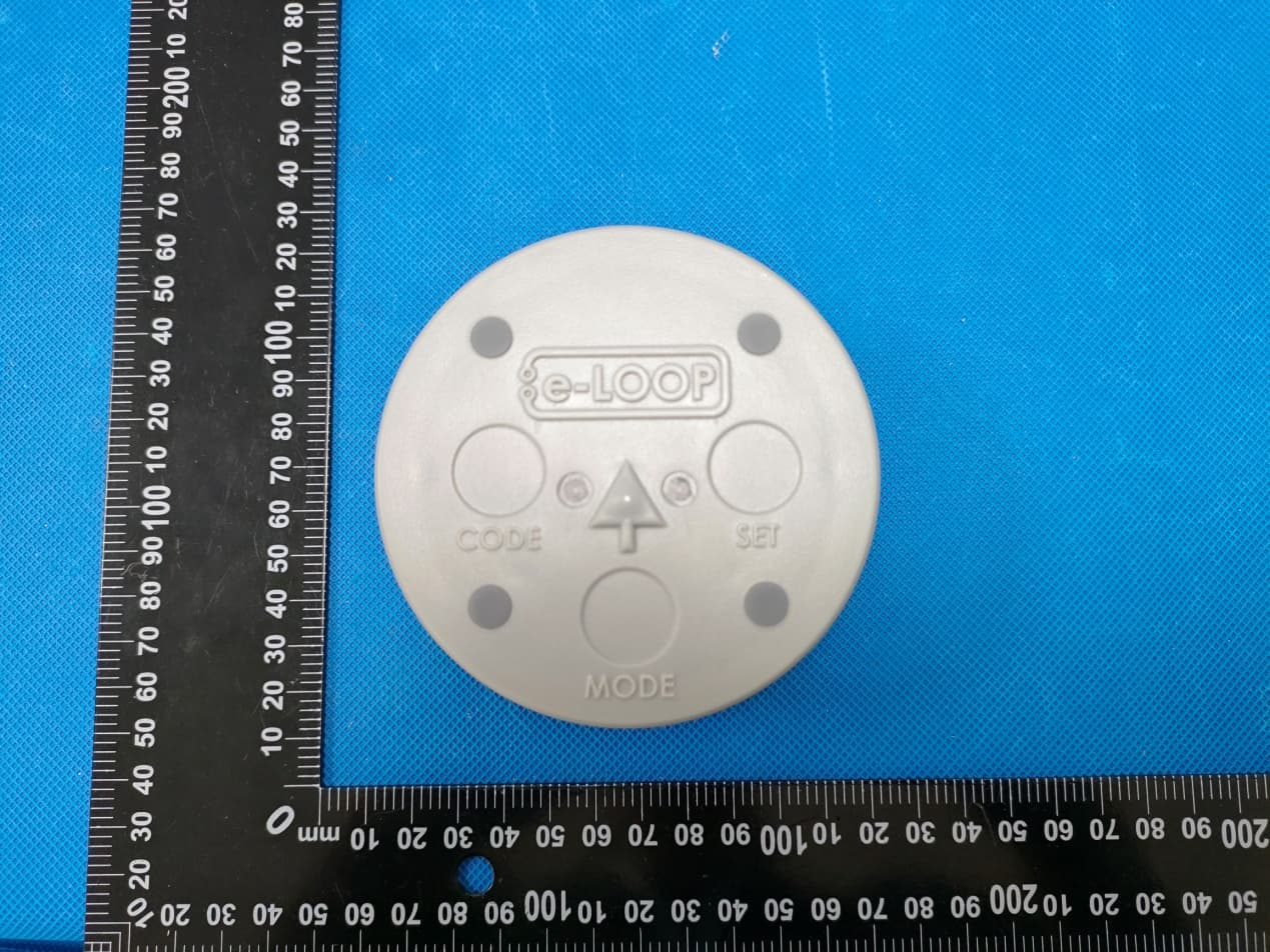
Annex A External Photos Report No.:HK2309184315-E Page 1 of 4 Report No.:HK2309184315-E Page 2 of 4 Report No.:HK2309184315-E Page 3 of 4 Report No.:HK2309184315-E Page 4 of 4
ID Label/Location Info
FCC ID LABEL: Ca. 10mm x 20mm Label Location FCC ID: 2A8PC-EL00C
Internal Photos
Annex B Internal Photo Report No.:HK2309184315-E Page 1 of 3 Report No.:HK2309184315-E Page 2 of 3 Antenna Report No.:HK2309184315-E Page 3 of 3
RF Exposure Info
FCC RF Exposure EUT Description: e‐LOOP Model No.: EL00C loops FCC ID: 2A8PC‐EL00C 1. Limits According to KDB 447498 D01 General RF Exposure Guidance v06 The 1‐g and 10‐g SAR test exclusion thresholds for 100 MHz to 6 GHz at test separation distances ≤50 mm are determined by: [(max power of channel, including tune‐up tolerance, mW)/(min. test separation distance, mm)]·[√ f(GHz)]≤3.0 for 1‐g SAR and ≤ 7.5 for 10‐g extremity SAR, Where: Result=P/D*√F F= the RF channel transmit frequency in GHz P=Maximum turn‐up power in mw D=Min. test separation distance in mm 2. Test Result of RF Exposure Evaluation 433.39MHz: EIRP(dBm)=67.97(dBuV/m)-95.2=-27.23(dBm) Frequency (MHz) Output power (dBm) Tune Up Power (dBm) Max Tune Up power dBm/mW Min test separatio n distance mm Result Limit (mW/cm 2 ) SAR Test Exclusion 433.39 ‐27.23 ‐27±1 ‐26/0.003 5 0.0003 3.0 Pass Note: PK Output power= conducted power. Conducted power see the test report HK2309184315‐E, antenna gain=0dBi Per KDB 447498 D01, when the minimum test separation distance is < 5 mm, a distance of 5 mm is applied to determine RF Exposure test exclusion. The test exclusion threshold is 0.0003 which is<= 3, RF Exposure testing is not required. Note: Exclusion Thresholds Results=[(max. power of channel, including tune-up tolerance, mW)/(min. test separation distance, mm)] ·[√f (GHz)] f(GHz) is the RF channel transmit frequency in GHz Distance=5mm
Test Report
antenna picture Transmitter: The thick line of the entire circle shape along the edge of the PCB pointed by the arrow is the transmitting antenna, with a length of 107.295mm and a width of 1.2 mm. Antenna Product Description : Operation Frequency:433.3845MHz Number of Channel:1 Channels Modulation Type:ASK Antenna Type:PCB Antenna Antenna Gain(Peak):0dBi
Test Report
Page 1 of 23 Report No.: HK2309184315-E Prepared for : Microtech Designs 3/45 Technology CT Hallam Victoria, Australia Prepared By : Shenzhen HUAK Testing Technology Co., Ltd. 1-2/F., Building B2, Junfeng Zhongcheng Zhizao Innovation Park, Heping, Fuhai Street, Bao’an District, Shenzhen, Guangdong, China Date of Test: Sept. 18, 2023 ~ Oct. 09, 2023 Date of Report: Oct. 09, 2023 Report Number: HK2309184315-E FCC Test Report Test report On Behalf of Microtech Designs For e-LOOP Model No.: EL00C loops FCC ID: 2A8PC-EL00C Applica Address Manufa Address Produc Trade M Product Model a Standa This pu b Shenzh the ma t assume due to it Date of Date (s ) Date of Te s t R e s ant’s name s ................ acture's Na s ................ ct descriptio Mark: t name ........ and/or type rds ............ blication ma en HUAK T terial. Shenz e liability for ts placemen Test .......... ) of performa Issue ......... sult ............ T T A ................. ................. me ............ ................. on .................... reference ................. ay be repro Testing Tech zhen HUAK r damages nt and conte .................. ance of test .................. .................. Testing Eng Technical M Authorized S Test R . : Microte c . : 3/45 Te c . : Microte c . : 3/45 Te c EL00C l o : e-LOOP . : EL00C l o . : FCC Pa r ANSI C6 duced in wh hnology Co K Te s t i n g Te resulting fr ext. ................ : ts ............. : ................ : ................ : gineer Manager Signatory Page 2 of 2 Result Ce ch Designs chnology CT ch Designs chnology CT oops oops rt15 Subpar 63.10: 2013 hole or in p o., Ltd. is ac echnology C rom the rea Sept. 18, Oct. 09, 2 Pass : : : 3 ertificatio T Hallam Vic T Hallam Vic rt C 2017, S art for non- cknowledge Co., Ltd. ta ader's interp 2023 ~ Oct. 2023 (Gary Q (Eden (Jason Z Rep on ctoria, Aust ctoria, Aust Section 15.2 commercia ed as copyr kes no resp pretation of 09, 2023 Qian) Hu) Zhou) port No.: HK tralia tralia 31 l purposes right owner ponsibility fo f the reprod K2309184315 as long as and sourc e or and will duced mate 5-E the e of not erial Page 3 of 23 Report No.: HK2309184315-E Contents 1 . Test Summary ..................................................................................................................................................... 5 1.1 Test Facility ................................................................................................................................................ 5 1.2 Information of the Test Laboratory .......................................................................................................... 5 1.3 Measurement Uncertainty........................................................................................................................ 5 2. General Information ............................................................................................................................................ 6 2.1. Description of Device (EUT) ................................................................................................................... 6 2.2. List of Channels ....................................................................................................................................... 6 2.3. Description of Test Setup ........................................................................................................................ 7 2.4. Description of Support Units .................................................................................................................. 7 2.5. Test Equipment List ................................................................................................................................. 8 3. Conducted Emission Test .................................................................................................................................. 9 3.1 Conducted Power Line Emission Limit .................................................................................................. 9 3.2 Test Setup .................................................................................................................................................. 9 3.3 Test Procedure .......................................................................................................................................... 9 3.4 Test Data .................................................................................................................................................. 10 4. Radiated Emissions ............................................................................................................................... ........... 11 4.1. Standard Applicable ............................................................................................................................... 11 4.2. Test Procedure ....................................................................................................................................... 11 4.3. Corrected Amplitude & Margin Calculation ........................................................................................ 13 4.4. Environmental Conditions ..................................................................................................................... 13 4.5. Test Data ................................................................................................................................................. 13 5. 20db Occupy Bandwidth Test .......................................................................................................................... 16 5.1. Standard Applicable ............................................................................................................................... 16 5.2. Test Procedure ....................................................................................................................................... 16 5.3. Test Data ..............................................................…
Text truncated - open the document above for the full version.
Test Setup Photos
Radiated Emission
Contact Information
Applicant
Glenn Fleming(Managing director)
Technical Contact
Test Firm
Shenzhen HUAK Testing Technology Co., Ltd.Jason Zhou
[email protected]86-755-23029901
Technical Specifications
| # | Rule Parts | Frequency Range | Power Output |
|---|---|---|---|
| 1 | 15.231 | 433.39 MHz - 433.39 MHz | - |
Other Applications from Microtech Designs
2A8PC-EL00IG
Oct 15, 2023e-LOOP
Equipment Class
DSC - Part 15 Security/Remote Control Transmitter