2A8PS-HCPZWLKR1SHZ-Wave 700 Module (KR)
ASSA ABLOY (China) Investment Company Limited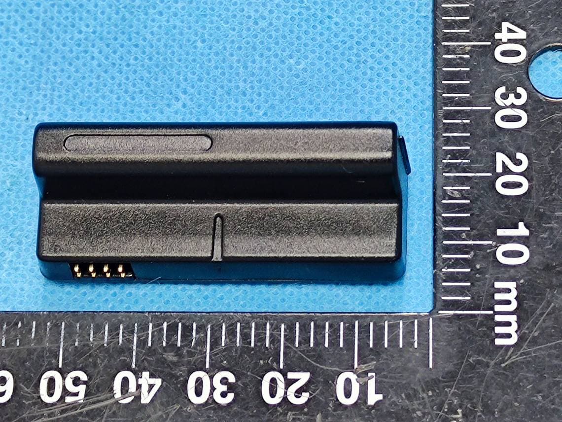
Click to zoom
Application Details
- Equipment Class
- DXX - Part 15 Low Power Communication Device Transmitter
- Date of Grant
- Nov 08, 2022
- Application Purpose
- Original Equipment
- Date of Application
- Nov 08, 2022
- Equipment Note
- Z-Wave 700 Module (KR)
- Frequency Range
- 908.40000000 - 908.40000000
- Country
- China
Documents & Files
Document Text
Text extracted from the exhibit documents filed with the FCC. Open a document above to read the original.
Users Manual
User Manual Model: HCP Lshape ZW3 ANZ / HCP Lshape ZW3 EMEA/ HCP Lshape ZW3 KR 2 Table of Contents 1 FEATURES & SPECIFICATIONS ........................................................................................................................3 1.1 HARDWARE CHARACTERISTICS ...........................................................................................................................3 1.2 SOFTWARE CHARACTERISTICS ............................................................................................................................3 2 PRODUCT QUICK START ................................................................................................................................5 2.1 WHAT IS Z-WAVE ..........................................................................................................................................5 2.2 WHAT IS SMARTSTART ....................................................................................................................................5 2.3 HOW TO ADD (PAIRING) THE PRODUCT INTO Z-WAVE NETWORK ................................................................................5 2.4 HOW TO REMOVE THE PRODUCT FROM Z-WAVE NETWORK ......................................................................................5 2.5 HOW TO FACTORY RESET FOR Z-WAVE ................................................................................................................5 2.6 Z-WAVE DSK LOCATION ..................................................................................................................................5 2.6.1 HOW TO LOCATE THE DSK REPRESENTATION ON THE PRODUCT ....................................................................................... 5 2.6.2 HOW TO ACCESS THE DSK REPRESENTATION VIA THE UI ................................................................................................ 5 3 SOFTWARE FUNCTION DEFINITION ................................................................................................................6 3.2 SUPPORTED COMMAND CLASSES .......................................................................................................................6 3.2.1 INDICATOR COMMAND CLASS ................................................................................................................................... 7 3.3 BASIC COMMAND CLASS MAPPING .....................................................................................................................7 3.4 Z-WAVE PLUS INFO ........................................................................................................................................8 3.5 VERSION ......................................................................................................................................................9 3.6 ASSOCIATION GROUP INFO ...............................................................................................................................9 3.6.1 GROUPING IDENTIFIER ............................................................................................................................................ 10 3.6.2 MAXIMUM NUMBER OF DEVICES THAT CAN BE ADDED TO THE GROUP ............................................................................ 10 3.7 DEVICES FROM MULTIPLE MANUFACTURES ........................................................................................................ 11 3.8 IMPLEMENTED NOTIFICATION TYPES AND EVENTS ................................................................................................ 11 3.9 CONFIGURATION PARAMETERS AVAILABLE IN THE PRODUCT ................................................................................... 11 3 1 FEATURES & SPECIFICATIONS 1.1 Hardware Characteristics Parameter Value Z-Wave Module ZGM130S Z-Wave Antenna Distance 40m (Indoor) /150m (Outdoor) Input Voltage 3.6-6.0V from the lock Working Current RX: 9.8 mA TX: 13.3 mA Standby Current 0.8μA 1.2 Software Characteristics Parameter Value Wireless Technology Z-Wave Certification Type Z-Wave Plus v2 Z-Wave SDK Version 7.16.3 Z-Wave Library Type Enhanced 232 Slave Z-Wave Role Type ZWAVEPLUS_INFO_REPORT_ROLE_TYPE_SLAVE_SLEEPING_LISTENING (0x07) Generic Device Type GENERIC_TYPE_ENTRY_CONTROL (0x40) Specific Device Type SPECIFIC_TYPE_DOOR_LOCK (0x01) Security Class S0, S2-ACCESS Smart Start Support. After powering on, Smart Start is auto active if it’s out of the Z -Wave network. Over The Air (OTA) Support. Firmware can be updated via RF. Multichannel Device No 4 Association Support. Refer to Section 3.2 Association Group Info. Factory Reset Support. Refer to Section 2.5 How to factory reset. Power-down Memory Support. All command settings will stay unchanged even power down. Timed battery report Support. Low battery warning Support. Door State Report Support. When door lock mode changed, send out notification via Group 1. Note: Z-Wave 700 Module cannot be used independently. It should be used with the lock ( Yale). The picture of the Z-Wave 700 Module is below: The pin adapted to the lock 5 2 PRODUCT QUICK START 2.1 What is Z-Wave Z-Wave is the international wireless protocol for communication in the Smart Home. Z-Wave ensures a reliable communication by reconfirming every message (two-way communication) and every mains powered node can act as a repeater for other nodes (meshed network) in case the receiver is not in direct wireless range of the transmitter. This device and every other certified Z-Wave device can be used together with any other certified Z-Wave device regardless of brand and origin as long as both are suited for the same frequency range. 2.2 What is SmartStart SmartStart enabled products can be added into a Z-Wave network by scanning the Z-Wave QR Code present on the product with a controller providing SmartStart inclusion. No further action is required and the SmartStart product will be added automatically within 10 minutes of being switched on in…
Text truncated - open the document above for the full version.
Attestation Statements
Company Name: ASSA ABLOY (China) Investment Company Limited Address: 7th F, Building 11, SkyBridge HQ, No. 968, Jinzhong Rd 200335 Changning Dis. Shanghai, China Telephone: 021-60842888 Email: [email protected] ATTESTATION LETTER Date: 2022 -10-13 FEDERAL COMMUNICATIONS COMMISSIONS Authorization and Evaluation Division 7435 Oakland Mills Road Columbia, MD 21046 We, ASSA ABLOY (China) Investment Company Limited hereby declare that: Product Name: Z-Wave 700 Module (KR) Model Number: HCP Lshape ZW3 KR FCC ID: 2A8PS-HCPZWLKR1SH For the RF chip (model: ZGM130S): 912MHz and other frequency are disabled by software. Only below are activated. 908.4MHz Except for the manufacturer, the end user does not have any capability to modify/change the RF parameters. We acknowledge that it is the manufacturer’s responsibility to provide the radio configurations to ensure compliance with Commission’s rules. Client’s Signature Client’s Name/Title: Francis Liu / Project Manager
Cover Letter(s)
Company Name: ASSA ABLOY (China) Investment Company Limited Address: 7th F, Building 11, SkyBridge HQ, No. 968, Jinzhong Rd 200335 Changning Dis. Shanghai, China Telephone: 021-60842888 Email: [email protected] QA-FR-170-B FCC Authorization Current Date: 2022-10-13 FEDERAL COMMUNICATIONS COMMISSIONS Authorization and Evaluation Division 7435 Oakland Mills Road Columbia, MD 21046 Subject: Agent Authorization To whom it may concern: We ASSA ABLOY (China) Investment Company Limited, the undersigned, Hereby authorizes CHINA CERTIFICATION ICT CO.,LTD (DONGGUAN) to act on its behalf in all matters relating to application for Equipment authorization, including the signing of all documents relating to these matters. All acts carried out by CHINA CERTIFICATION ICT CO.,LTD (DONGGUAN) on our behalf shall have the same effect as our own action. We, the undersigned, hereby certify that we are not subject to a denial of federal benefits, that includes FCC benefits, pursuant to Section 5301 of the Anti-Drug Abuse Act of 1988, 21 U.S.C. 862. This authorization is valid until further written notice from the applicant. Sincerely Yours, Client’s Signature Client’s Name/Title: Francis Liu / Project Manager
Cover Letter(s)
Company Name: ASSA ABLOY (China) Investment Company Limited Address: 7th F, Building 11, SkyBridge HQ, No. 968, Jinzhong Rd 200335 Changning Dis. Shanghai, China Telephone: 021-60842888 Email: [email protected] FCC Confidential Authorization Current Date: 2022-10-13 FEDERAL COMMUNICATIONS COMMISSIONS Authorization and Evaluation Division 7435 Oakland Mills Road Columbia, MD 21046 Confidentiality Request regarding application for certification of FCC ID: 2A8PS-HCPZWLKR1SH Pursuant to Sections 0.457 and 0.459 of the Commission’s Rules, we hereby request confidential treatment of information accompanying this application as outlined below: Circuit Description --- (Long term) Schematic --- (Long term) Block Diagram --- (Long term) The above materials contain trade secrets and proprietary information not customarily released to the public. The public disclosure of these materials may be harmful to the applicant and provide unjustified benefits to its competitors. The applicant understands that pursuant to Section 0.457 of the Rules, disclosure of this application and all accompanying documentation will not be made before the date of the Grant for this application. Sincerely, Client’s Signature Client’s Name/Title: Francis Liu / Project Manager
External Photos
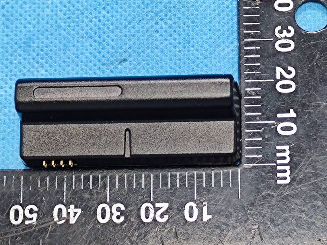
EXHIBIT B - EUT EXTERNAL PHOTOGRAPHS EUT Port
ID Label/Location Info
Label and label location Label(part1): Label (part2):
Internal Photos
EXHIBIT C - EUT INTERNAL PHOTOGRAPHS Uncover Chip Antenna
Test Report
TEST REPORT Applicant: ASSA ABLOY (China) Investment Company Limited Address: 7th F, Building 11, SkyBridge HQ, No. 968, Jinzhong Rd 200335 Changning Dis. Shanghai, China FCC ID: 2A8PS-HCPZWLKR1SH Product Name: Z-Wave 700 Module (KR) Model: HCP Lshape ZW3 KR Standard(s): 47 CFR Part 15, Subpart C(15.249) ANSI C63.10-2013 The above equipment has been tested and found compliant with the requirement of the relative standards by China Certification ICT Co., Ltd (Dongguan) Report Number: CR220941397-00 Date Of Issue: 2022-11-03 Reviewed By: Sun Zhong Title: Manager Test Laboratory: China Certification ICT Co., Ltd (Dongguan) No. 113, Pingkang Road, Dalang Town, Dongguan, Guangdong, China Tel: +86-769-82016888 China Certification ICT Co., Ltd (Dongguan) Report No.: CR220941397-00 Page 2 of 28 Test Facility The Test site used by China Certification ICT Co., Ltd (Dongguan) to collect test data is located on the No. 113, Pingkang Road, Dalang Town, Dongguan, Guangdong, China. The lab has been recognized as the FCC accredited lab under the KDB 974614 D01 and is listed in the FCC Public Access Link (PAL) database, FCC Registration No. : 442868, the FCC Designation No. : CN1314. The lab has been recognized by Innovation, Science and Economic Development Canada to test to Canadian radio equipment requirements, the CAB identifier: CN0123. Declarations China Certification ICT Co., Ltd (Dongguan) is not responsible for the authenticity of any test data provided by the applicant. Data included from the applicant that may affect test results are marked with a triangle symbol “▲”. Customer model name, addresses, names, trademarks etc. are not considered data. Unless otherwise stated the results shown in this test report refer only to the sample(s) tested. This report cannot be reproduced except in full, without prior written approval of the Company. This report is valid only with a valid digital signature. The digital signature may be available only under the Adobe software above version 7.0. This report may contain data that are not covered by the accreditation scope and shall be marked with an asterisk “★”. China Certification ICT Co., Ltd (Dongguan) Report No.: CR220941397-00 Page 3 of 28 CONTENTS T EST FACILITY .......................................................................................................................................... 2 DECLARATIONS .......................................................................................................................................... 2 1. GENERAL INFORMATION .................................................................................................... 4 1.1 PRODUCT DESCRIPTION FOR EQUIPMENT UNDER TEST (EUT) ....................................................... 4 1.2 DESCRIPTION OF TEST CONFIGURATION ........................................................................................... 5 1.2.2 Support Equipment List and Details .............................................................................................................. 5 1.2.3 Support Cable List and Details ...................................................................................................................... 5 1.2.4 Block Diagram of Test Setu ........................................................................................................................... 5 1.3 MEASUREMENT UNCERTAINTY .......................................................................................................... 7 2. SUMMARY OF TEST RESULTS ............................................................................................ 8 3. REQUIREMENTS AND TEST PROCEDURES .................................................................... 9 3.1 AC LINE CONDUCTED EMISSIONS ...................................................................................................... 9 3.1.1 Applicable Standard ....................................................................................................................................... 9 3.1.2 EUT Setup.................................................................................................................................................... 10 3.1.3 EMI Test Receiver Setup ............................................................................................................................. 10 3.1.4 Test Procedure ............................................................................................................................................. 11 3.1.5 Corrected Amplitude & Margin Calculation ................................................................................................ 11 3.2 RADIATED EMISSIONS ....................................................................................................................... 12 3.2.1 Applicable Standard ..................................................................................................................................... 12 3.2.2 EUT Setup.................................................................................................................................................... 12 3.2.3 EMI Test Receiver & Spectrum Analyzer Setup ......................................................................................... 13 3.2.4 Test Procedure ............................................................................................................................................. 13 3.2.5 Corrected Amplitude & Margin Calculation ................................................................................................ 14 3.3 20 DB EMISSION BANDWIDTH: .......................................................................................................... 15 3.3.1 Applicable Standard ..................................................................................................................................... 15 3.3.2 EUT Setup.......................................................................…
Text truncated - open the document above for the full version.
Test Setup Photos
EXHIBIT D - TEST SETUP PHOTOGRAPHS Conducted Emissions Front View Conducted Emissions Side View Radiated Emission Below 1GHz View Radiated Emission Above 1GHz View
Contact Information
Applicant
Francis Liu(Project Manager)
Test Firm
CHINA CERTIFICATION ICT CO., LTD (DONGGUAN)Tanie Ou
[email protected]0086 0769 86858888
Technical Specifications
| # | Rule Parts | Frequency Range | Power Output |
|---|---|---|---|
| 1 | 15C | 908.4 MHz - 908.4 MHz | - |
Other Applications from ASSA ABLOY (China) Investment Company Limited
2A8PS-HCPZWLEMEA1SH
Nov 08, 2022Z-Wave 700 Module (EMEA)
Equipment Class
DXX - Part 15 Low Power Communication Device Transmitter