2A8SB30158User interface, driver identification and behavior
MASTERNAUT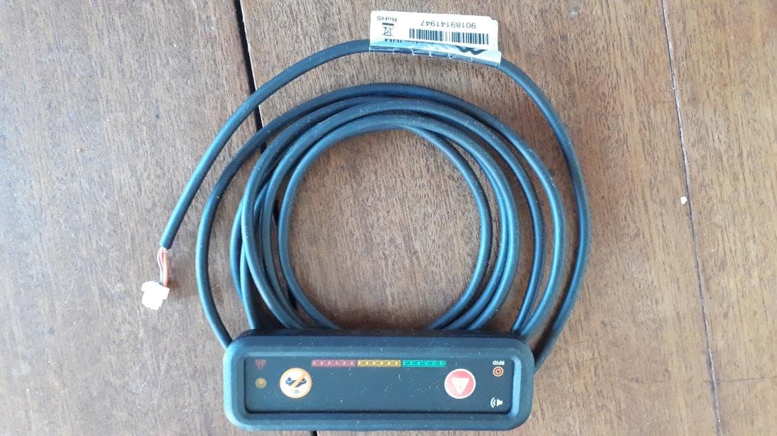
Click to zoom
Application Details
- Equipment Class
- DXX - Part 15 Low Power Communication Device Transmitter
- Date of Grant
- Nov 10, 2022
- Application Purpose
- Original Equipment
- Date of Application
- Nov 10, 2022
- Equipment Note
- User interface, driver identification and behavior
- Frequency Range
- 13.56000000 - 13.56000000
- Company
- MASTERNAUT
- Country
- France
Documents & Files
Document Text
Text extracted from the exhibit documents filed with the FCC. Open a document above to read the original.
Users Manual
16 Product Install Guide – M4xx Series 03/11/22 | V1.9.9 GSM, GSM/LTE & GPS positions (M40x) Dual Antenna (GSM/GPS) (M400/3) The dual antenna (GSM/GPS) should only be installed overtly on the windscreen. In the same way as the overtly installed GSM antenna. You must maintain 1.2 inches (3 cm) between any metal and the dual antenna. Note and raise any damage or weakness to the windscreen during the pre-check. Confirm with MICHELIN Connected Fleet and the customer if the antenna should be fitted. Adapt the sticking pressure accordingly. The area needs to be clean before attaching the antenna, use the included alchohol wipe to clean it. At the bottom of the a-pillar. Behind the dash. On the the a-pillar trim.Behind a panel. GPS POSITION EXAMPLES: COVERT GSM & GSM/LTE POSITION EXAMPLES: POSITION MOUNTING Alchohol wipe included OVERT GSM (CLASSIC) OVERT GSM (THERMAL) 12. Antennas 17 Product Install Guide – M4xx Series 03/11/22 | V1.9.9 1. Open the CAN sensor. There are four clips that you need to undo. 2. There are two labelled channels one for CAN High and one for CAN Low. 3. Locate the CAN wire pair, untwist them slightly. 4. Run the wires in the correct labelled channels in the sensor. They should NOT cross over. 5. Close the sensor, taking care to not damage or move the wires, you should hear a click. Secure the sensor with one of the included cable ties. Use the other cable tie 5-10 cm further down to relieve pressure on the wires. The MICHELIN Connected Fleet CAN sensors are unintrusive to the vehicle CAN and have read only functionality. This means that the CAN sensors can’t input any data on to the network that might cause issues with the vehicle. Ignition MUST be off while connecting the CAN clips. The clips come in two varieties: • CAN, white label Sonde SCN4 • J1587, green label Sonde SCN4 Depending on the vehicle make and model you might require one or two CAN sensors. Most vehicles only require one clip. This means that your CAN setup will look like one of these three options: • CAN; one white labelled sensor • CAN+CAN; two white labelled sensors • CAN+J1587; one white labelled sensor and one green labelled sensor NOTE: A J1587, green label, sensor will work as a replacement for a CAN, white label, sensor. However the green clip should only be used when needed. NOTE: The CANClip must be installed behind the dash trim of the vehicle and not accessible to the end user (driver). 12. CAN (Optional) 1 2 3 4 5 18 Product Install Guide – M4xx Series 03/11/22 | V1.9.9 Privacy ButtonPanic/Alert Button Buzzer Driver ID with RFID Driver feedback LEDs The HMI or Lightbar features the following: • Driver Identification by RFID tags • Panic/Alert button • Privacy button • Driver behaviour bar graph with 18 LED • Buzzer, for login reminder and driver behaviour alerts The HMI MUST be clearly visible from the driver’s seat, to prevent the driver from taking the eyes off the road. Installing the HMI on the central console may be preferable as it generally allows it to be positioned higher. If this is not possible the HMI can be installed on the dash between the steering wheel and the door. Refer to the MICHELIN Connected Fleet vehicle guides for recommended HMI positions for the vehicle you are working on. FEATURES INSTALLATION POSITION The HMI is installed by pre-applied adhesive to the back of the lightbar. The area must be clean. Use the included alcohol wipe to clean the area before attaching the HMI. NOTE: If possible avoid making a visible notch in panels to route the HMI cable. If needed make sure that the notch is small and neatly done with proper tools. NEVER make a hole in the middle of a panel. Alchohol wipe included RHD - Skoda Superb 3RHD - VW Crafter 2LHD - Ford Transit 2T LHD - M-B Vito W447LHD - Renault Trafic 3LHD - Iveco Eurocargo 13. HMI (Optional) HMI POSITION EXAMPLES: 19 Product Install Guide – M4xx Series 03/11/22 | V1.9.9 LOOMING Any excess cabling should be loomed up tidily in a figure eight, and tied together with cable ties and tape. Excess cabling should not be looped. All MICHELIN Connected Fleet cables should be gathered up and loomed up into one loom. Best PracticeBad Practice ROUTING To minimise electrical interference the MICHELIN Connected Fleet wiring should be run along the existing vehicle wiring or the metal structure of the vehicle. The cables should be fastened with cable ties approximately every 4 inches, 10 cm. MICHELIN Connected Fleet wiring and equipment MUST NOT obstruct or interfere with any of the following: AirbagsDay to day operationVehicle servicingOther equipment Red - MICHELIN Connected Fleet wiringGreen - Original wiring Blue - Cable ties 14. Cable routing 20 Product Install Guide – M4xx Series 03/11/22 | V1.9.9 The M4xx has an integrated 3 axes accelerometer, which is used to confirm harsh driving events and register impact force in the event of a crash. To avoid water ingress and condensation forming DO NOT fit the M4xx with the connectors facing upward. To achieve optimal performance, and for security reasons, the M4xx must be firmly secured, using cable ties. To a solid plastic or metal structure in the vehicle. SECURING THE UNIT ORIENTATION The M4xx must be mounted in a safe place, where it will not affect the operation of the vehicle. It should also not be subject to damp that might compromise the unit. NOTE: The M4xx must be installed behind the dash trim of the vehicle and not accessible to the end user (driver). POSITIONING MOUNTING EXAMPLES Ford Transit - 2T - Euro 6 Skoda Superb - 3 Follow instructions in § “Internal antennas (M41x)” on page 13 for optimal reception from the internal antennas. M41x X YZ Init DefaultGSM/GPRSGPSCAN Y X Z 15. Unit Mounting 21 Product Install Guide – M4xx Series 03/11/22 | V1.9.9 ATTACHING THE I/O PROTECTION CLIPS WARRANTY/TAMPER STICKERS Warranty/Tamper stickers must be added to the M4xx SIM card slot, I/O Shield, and the fuses on the power loom. There are currently two sizes of Warranty/Tamper stickers:…
Text truncated - open the document above for the full version.
Users Manual
03/11/22 CAN GPS GSM/GPRS Default Init M4xx Series PRODUCT INSTALL GUIDE V1.9.9 10001 Christian Ståhle eLearning Team - MCF Internal Reference No: Version: Date of Version: Author: Approved by: Translated by: Classification: 2 Product Install Guide – M4xx Series 03/11/22 | V1.9.9 1. table of contents 1. TABLE OF CONTENTS 2 2. IMPORTANT NOTES 4 3. REQUIRED TOOLS AND CONSUMABLES 5 4. M4XX VERSIONS 6 5. PARTS 7 6. WIRING DIAGRAM 8 M40X 8 M41X 9 VEHICLE SPECIFICS 10 7. POWER SUPPLY 10 +POWER 10 +IGNITION 10 GROUND 10 POWER I/O CONNECTOR 10 8. IGNITION 11 9. SOLDERING METHOD 12 10. CRIMPING TERMINAL METHOD 12 11. ANTENNAS 13 INTERNAL ANTENNAS (M41X) 13 GSM & GSM/LTE ANTENNA (M40X) 15 GPS ANTENNA (M40X) 15 GSM, GSM/LTE & GPS POSITIONS (M40X) 16 DUAL ANTENNA (GSM/GPS) (M400/3) 16 12. CAN (OPTIONAL) 17 13. HMI (OPTIONAL) 18 INSTALLATION 18 POSITION 18 FEATURES 18 14. CABLE ROUTING 19 LOOMING 19 ROUTING 19 15. UNIT MOUNTING 20 SECURING THE UNIT 20 ORIENTATION 20 POSITIONING 20 M41X 20 3 Product Install Guide – M4xx Series 03/11/22 | V1.9.9 1.table of contents 16. I/O PROTECTION AND WARRANTY/TAMPER SEALS 21 ATTACHING THE I/O PROTECTION 21 WARRANTY/TAMPER STICKERS 21 17. COMMISSIONING 22 MASTER MANAGER MOBILE 22 VEHICLE INFORMATION 22 CONFIGURATION 22 INSTALL INFORMATION 22 VALIDATION 22 SPECIALIST SOLUTIONS 22 18. INPUT/OUTPUT (OPTIONAL) 23 INPUT COMPATIBILITY 23 19. TACHOFRESH (OPTIONAL) 24 TACHOFRESH 24 COMPATIBILITY 24 WIRING 24 20. GRITTERS (OPTIONAL) 25 COMPATIBILITY 25 WIRING 25 21. TEMPERATURE (OPTIONAL) 26 COMPATIBILITY 26 WIRED PROBES WIRING 26 WIRED PROBES INSTALLATION 26 WIRELESS TEMPERATURE 26 22. DEVICE OVERVIEW 27 LED SEQUENCE TROUBLESHOOTING 27 UNIT ICONOGRAPHY 27 23. CERTIFICATION INFORMATION 28 USA FCC - M405 / M404 + HMI + SCN4 28 CANADA ISED - M405 / M404 + HMI + SCN4 28 SOUTH AFRICA ICASA - M405 / M404 + HMI + SCN4 28 AUSTRALIA AND NEW ZEALAND RCM - M405 + HMI + SCN4 28 24. CONTACTS 29 25. VERSION HISTORY 29 FROM V 1.9.9 ONWARDS 29 4 Product Install Guide – M4xx Series 03/11/22 | V1.9.9 NOTE! Read carefully this contains important information. • Before you begin installing and commissioning this equipment please ensure that you have read this manual thoroughly referring to any supplementary information provided for the OBU as required. • Failure to comply with the following Warnings, Approval and Safety information may invalidate the warranty, certification or type approval of this product. • In order to maximise any insurance discounts that may apply it is essential that all installation and service work is carried out in regulations of the country. It is strongly recommended that the OBU (On Board Unit) is installed and commissioned by suitably trained and qualified personnel, accredited and registered by the Vehicle Systems Installation Board. • Before working on any connectors or wires, turn the ignition OFF and wait 5 minutes, for sleep mode to kick in. • Never turn the ignition ON if a connector is disconnected. • A battery conditioning test must be completed during the pre-installation vehicle checks. If the battery is defective, or requires recharging you must inform the customer and record this in your report before proceeding with the installation. • Never operate the OBU without the correct antennas, or suitable artificial loads, connected. • To minimise interference 20 cm (7.87 inch) must be maintained between the GSM antenna and the GPS antenna, all persons, and electronic components. • The user of all or part of the equipment is warned that any changes or modifications not expressly approved by Masternaut may prohibit its use. • With the exception of specific installations with properly rated parts, this equipment should not be operated in hazardous environments e.g; areas with flammable vapours or explosive materials. • This equipment should not be operated within aircrafts or in close proximity to medical equipment. • This equipment may only be located in a position where it cannot interfere with the normal operation of the vehicle or present a hazard to the driver or passengers. Care must also be taken when the routing the cables so that the insulation does not become worn or damaged. The cables must not be in contact with the mechanical parts of the vehicle (e.g. steering, pedals, etc.). • Under no circumstances may any part of the OBU be installed inside the engine compartment. • Always use special tools when disassembling the dash board and a multimeter to check all connections. • Warranty/tamper seals must be used. • Tidy the vehicle after you, do not leave any bits of wire or pieces of tape behind. 2. Important Notes ! 5 Product Install Guide – M4xx Series 03/11/22 | V1.9.9 TorchTorx screwdriversPlastic LeverFlat screwdrivers MultimeterPlastic CutterWire CutterWire Stripper Crimping ToolHeat Gun (Gas)Round FileDrill Reinforced Tape Ratchet Ring Terminals Soldering IronSolder Wire Cable Ties (different sizes) Amalgamating Tape Heatshrink 3. Required Tools and Consumables 6 Product Install Guide – M4xx Series 03/11/22 | V1.9.9 M400 / M403 M404 / M405 M410 M414 / M415 External Antennas Internal Antennas GSM LTE NOTE: For instructions that do not refer to the full M4xx series will be referred to as follows: M40x = M400, M403, M404 & M405 M400/3 = M400 & M403 M41x = M410, M414 & M415 4. M4xx versions 7 Product Install Guide – M4xx Series 03/11/22 | V1.9.9 Power Loom 070196 Security Seal 071211 GPS 040215 (M400/3) GSM 040101 (M400/3) GPS/GSM 040303 (M400/3) SCN4 CAN #1 White Label 030433 SCN4 CAN/J1587 #2 Green Label 030438 HMI Sustainability+ 031118 Kline + D8 Interface 030637 D8 Cable 030628 Kline Cable 030628 Gritter Cable Serial 030920/030909 4RS232 Adapter 030627 Gritter Cable XLR 030913 GSM/LTE 040112 (M404 / M405) Tachofresh hinterer CANBUS 030631 Tachofresh & Gritter Parts 5. Parts CAN GPS GSM/GPRS Default Init M4xx 8 Product Install Guide – M4xx Series 03/11/22 | V1.9.9 K-LINE + D8 INTERFACE OR OR OR OR 1. Power (+) - 5A Fused 2. Ground (-) 3. Ignition …
Text truncated - open the document above for the full version.
Cover Letter(s)
1, Avenue des Falaises 27100 Val de REUIL FRANCE Cover Letter Val de Reuil, Oct-14 th 2022 Subject RADIO Certification of HMI Applicant MASTERNAUT – Pierre Grenet Product (PMN) HMI Model (HVIN) 30158 Host (HMN) M405, M404, M414, M415 Unit FCC ID 2A8SB30158 IC ID 29178-30158 To Whom It May Concern: We would like to submit the above product for Certification concerning FCC and ISED rules for a new single certification in modular approval. Please review all required documents enclosed. This application is installed inside vehicle. It displays, with color leds, driver behavior information, allows the driver identification with an RFID reader and includes a private mode of operation. Compliance for RF exposure requirement is demonstrated in test report. If you have any queries, please do not hesitate to contact us. Regards, Pierre GRENET on October-14 th , 2022
Cover Letter(s)
1, Avenue des Falaises 27100 Val de REUIL FRANCE Permanent Confidentiality Letter Federal Communications Commission Authorization and Evaluation Division Val de Reuil, Oct-14 th 2022 Subject: Confidentiality Request regarding application for certification of FCC ID: 2A8SB30158 Applicant: MASTERNAUT – Pierre GRENET Product: HMI Model: MA-30158 or 720-31200 To Whom It May Concern: Pursuant to Sections 0.457 and 0.459 of the Commission’s Rules, we hereby request confidential treatment of information accompanying this application as outlined below: Exhibit Type File Name Block Diagram Schematics Operational Description Parts List BlkDia_RPT_834_01 720-31200 HMI Sus Block Diagram.pdf BlkDia Schem_720-31200_SCH_CEC000660_00_HMI.pdf Schem OpDes_FPM_72031200_03 HMI Sustainability Clickmate.pdf Opdes PartsLst_720-31200-004_HMI_BOM.pdf PartsLst [NB : No other file can be considered as confidential (exple : Test report)] The above materials contain trade secrets and proprietary information not customarily released to the public. The public disclosure of these materials may be harmful to the applicant and provide unjustified benefits to its competitors. The applicant understands that pursuant to Section 0.457 of the Rules, disclosure of this application and all accompanying documentation will not be made before the date of the Grant for this application. If you have any queries, please do not hesitate to contact us. 1, Avenue des Falaises 27100 Val de REUIL FRANCE Regards, Pierre GRENET on October-14 th , 2022
Cover Letter(s)
1, Avenue des Falaises 27100 Val de REUIL FRANCE Attn: TIMCO Engineering Inc. 849 N.W. State Road 45 P.O. Box 370 Newberry, Florida 32669 Authority to Act as Agent On our behalf, I appoint M. Bruno Pellerin from Emitech Montigny – 30 Avenue des 3 Peuples – 78180 Montigny Le Bretonneux, to act as our agent in the preparation of this application for equipment certification. I certify that submitted documents properly describe the device or system for which equipment certification is sought. I also certify that each unit manufactured, imported or marketed, as defined in the Federal Communications Commission’s regulations will have affixed to it a label identical to that submitted for approval with this application. For instances where our authorized agent signs the application for certification on our behalf, I acknowledge that all responsibility for complying with the terms and conditions for certification, as specified by TIMCO Engineering Inc., still resides with MASTERNAUT, 1 Avenue des Falaises 27100 VAL DE REUIL FRANCE. This authorization is valid until further written notice from MASTERNAUT. The October-14 th 2022 By Pierre GRENET, R&D Project Manager.
External Photos
HMI external pictures HMI HMI Label position on cable HMI Label
ID Label/Location Info
Noteable Information "BOM Notes" field of label can define suppression of logos if required. Vinyl Label, 36 x 14 mm printing, shall conform to UL969 and resist solvents. 3 mm 1 Avenue des Falaises 27 100 Val de Reuil France Project SizePart Number DescriptionSheet Drawn by:Checked by: < SKU >1 mmP.O. < Supply >1 mm Min text height <TITLE >2 mmSOP-00003 Designation C.HEPBURN Initial version at scale 2:1 IHM sustainability Product Assembly Label L.SAUDE / DateRev. 07/01/22001 440-00026A4 NI 1.5 mmDrawing < ECE-R10 >, < Atex >2 mmSOP-00003 1 of 1 Bar-code value: < sn >3 mmCode 128 Type C Other text1 mmDrawing < SN > Legacy 18 digits1.5 mmSOP-00003 CE, FCC & UK-CA logos definition Minimum height = 5mm Refer to a = 3.33 mm min SOP-00003 Company Title (Masternaut) < SKU > Masternaut < Title > < Supply > < ECE-R10 > Exx < SN > < Atex > FCC ID: 2A8SB30158 IC: 29178-30158
ID Label/Location Info
HMI HMI Label position on cable HMI Label example
Internal Photos
HMI PCBA bottom viewwith Lexan HMI PCBA top view HMI withoutcomponents, bottomviewof PCB HMI withoutcomponents, top viewof PCB
Test Report
Siège Social : Emitech - 3, avenue des Coudriers - Z.A. de l’Observatoire - 78180 MONTIGNY LE BX - France Siret : 344 545 645 00022 - Tél. : 33 (0)1 30 57 55 55 - Fax : 33 (0)1 30 43 74 48 - E-mail : [email protected] - URL : www.emitech.fr SAS au capital de 1 560 000 € - R.C.S. VERSAILLES 344 545 645 - APE 7112B RRA-EMIESS22L909MAS-02A v1 Duplication of this test report is only permitted for an integral photographic facsimile. It includes the number of pages referenced here above. This document is the result of testing a specimen or a sample of the product submitted. It does not imply an assessment of the conformity of the whole manufactured products of the tested sample. LIST OF ACCREDITED SITES AND SCOPE AVALAIBLE ON WWW.COFRAC.FR TESTING ACCREDITATIONS N° 1-0826, 1-0827, 1- 1925, 1-2069,1-2070, 1-2206, 1-2376 & 1-6086 “This report cancels and replaces the test report N° RRA-EMIESS22L909MAS-02A v0” Test report issued under the responsibility of: EMITECH ILE DE FRANCE Laboratory MRA US-EU Designation Number: FR0004 IC Assigned Code: 4379A RADIO TESTS REPORT FCC 47 CFR PART 15 : 2022 (§15.225) RSS-210_Issue 10 : 2019 RSS GEN Issue 5 : 2018 / AMD1 : 2019 / AMD2 : 2021 Company ....................................... : MASTERNAUT Address. .......................................... : 1 Avenue des Falaises 27100 VAL DE REUIL France Test item description. .................. : RFID reader Trade Mark. .................................... : MASTERNAUT Manufacturer................................... : MASTERNAUT Model/Type reference. .................... : HMI Ratings. ........................................... : 9 to 32 Vdc Testing Laboratory ....................... : EMITECH ILE DE FRANCE Laboratory Address. .......................................... : 30-32, AVENUE DES 3 PEUPLES 78180 MONTIGNY LE BRETONNEUX FRANCE Report Reference No. ................... : RRA-EMIESS22L909MAS-02A v1 Test procedure. .............................. : FCC and CANADA marking Diffusion. ......................................... : Mr. SAUDE Applicant’s name. ........................... : MASTERNAUT Date of issue. .................................. : 02/11/2022 Total number of pages. ................... : 34 Revision. ......................................... : 2 Compiled by. ................................... : C. ZIMMMERMANN (Tests Technician) Approved by (+ signature). ............. : RRA-EMIESS22L909MAS-02A v1 Page 2 out of 34 REPORT INDEX: 1. GENERAL INFORMATION ............................................................................................................................. 3 2. REFERENCE DOCUMENTS .......................................................................................................................... 4 3. EQUIPMENT TECHNICAL DESCRIPTION .................................................................................................... 5 3.1. TEST CONDITIONS ................................................................................................................................... 5 3.2. EUT OVERVIEW ...................................................................................................................................... 6 3.3. EUT MARKING PLATE .............................................................................................................................. 6 3.4. EUT MECHANICAL AND ELECTRICAL DESIGN ............................................................................................. 7 3.5. EUT INPUT/OUTPUT PORTS ...................................................................................................................... 7 3.6. SUPPORTING EQUIPMENT USED DURING TEST .......................................................................................... 8 3.7. EUT RADIO SPECIFICATIONS .................................................................................................................... 9 4. RESULT SUMMARY .....................................................................................................................................10 5. MEASUREMENT UNCERTAINTY ................................................................................................................12 6. TEST CONDITIONS AND RESULTS ...........................................................................................................13 6.1. UNINTENTIONAL RADIATED EMISSIONS IN THE BAND 9KHZ – 1GHZ ...........................................................13 6.2. UNINTENTIONAL RADIATED EMISSIONS AND TRANSMITTER UNWANTED EMISSION IN THE BAND 9 KHZ – 1GHZ 19 6.3. THE FIELD STRENGTH OF ANY EMISSION ..................................................................................................25 6.4. 20DB BANDWITH AND 99% OCCUPIED BANDWITH ....................................................................................28 6.5. FREQUENCY TOLERANCE OF THE CARRIER SIGNAL ..................................................................................32 REVISION HISTORY: Revision Date Modified pages Modifications v0 28/07/2022 Creation v1 17/10/2022 1, 5, 6, 7 Correction of EUT description 02/11/2022 2,28,29,30,31 Add 20 dB bandwith and 99% Occupied bandwith chapter RRA-EMIESS22L909MAS-02A v1 Page 3 out of 34 1. GENERAL INFORMATION This document submits the results of Radio tests performed on the equipment (denominated hereafter E.U.T.: equipment under test) according to documents listed in §2 of this test report. TESTING PROCEDURE AND TESTING LOCATION: Testing Laboratory ................................... : EMITECH ILE DE FRANCE Laboratory Address. ..................................................... : 30-32, AVENUE DES 3 PEUPLES 78180 MONTIGNY LE BRETONNEUX FRANCE Test procedure. .......................................... : FCC and CANADA marking Tested by .................................................... : C. ZIMMERMANN Test supervisor ........................................... : - Date of receipt of test item .................…
Text truncated - open the document above for the full version.
Contact Information
Applicant
Pierre GRENET(R&D Project Manager)
Test Firm
EMITECH MontignyFabien Verneiges
Technical Specifications
| # | Rule Parts | Frequency Range | Power Output |
|---|---|---|---|
| 1 | 15C | 13.56 MHz - 13.56 MHz | - |