2A8TA-M1Wireless Lavalier Microphone
Shenzhen Shengdaren Technology Co.,Ltd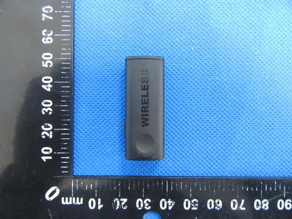
Click to zoom
Application Details
- Equipment Class
- DSS - Part 15 Spread Spectrum Transmitter
- Date of Grant
- Apr 08, 2023
- Application Purpose
- Original Equipment
- Date of Application
- Apr 08, 2023
- Equipment Note
- Wireless Lavalier Microphone
- Frequency Range
- 2402.00000000 - 2480.00000000
- Country
- China
Documents & Files
Document Text
Text extracted from the exhibit documents filed with the FCC. Open a document above to read the original.
Users Manual
Thank you for choosing our product. This product is a smart wireless microphone that provides profession- al-level recording output. Right now Plug and play, no APP is required. Multiple uses: webcast, Vlog shooting Filming, program interviews, interview recordings, video teaching, and other occasions. 方框内不包含出血尺寸 骑马钉 书写纸 Step 1: Plug the receiver into your device and you'll see a flashing red light. 1. Put the microphone transmitter into the fully charged microphone charging case to charge. 2. Or connect the microphone transmitter with the USB cable for charging 3. When charging, the front red light on the microphone will be on and will go off when it is fully charged. The receiver itself has no need to be charged, b ut you ca n charge your s martphone throug h the receiv er while you are recording and the mobile phone is in Wh en the receiver is plugged into the mobile phone and there is poor contact, it may be caus ed by dirt and dust on the receiv er plug. At thi s time, please use the cle aning eraser we provided to clean the receiver plug. 1. This device does not have a power adapter. When charging is required, please use a power adapter that has obtained the CCC certificate and complies with relevant standards. 2. Please use this equipment within the temperature range of 0°C-40°C, and store the equipment and accessories within the temperature range of-20°Cto +45°C. When the ambient temperature is too high or too low, it may cause equipment failure. 3. Do not expose the device to high temperatures or around heating devices, such as sunlight, heaters, microwave ovens, ovens or water heaters, etc. 4. When charging is complete or not charging, please disconnect the charger from the device and unplug the charger from the power. 5. The device is equipped with a non-removable built-in battery, please do not replace the battery yourself to avoid damage to the device. 6. Please dispose of this equipment, batteries, and related accessories following local regulations, and do not dispose of them as domestic waste. Q: Does this mic requir e video recording on the phone, or can I use it for au dio only through a different app? A: T his microphone works with the apps like a recorder, and camera on phone. It also works with apps TikTok, YouTube, and Facebook for video. Q: Ho w about the sound qual ity of this wireless microphone? A: Wirele ss microphone use s an upgraded noise canc ella tion chip, de signed to pro vide you with clearer audio. Q: Can two microphones be used a t the same time? A: Yes, two micropho nes can be u sed simultaneously. Q: Is the noise canceling mode tu rned on automatic ally? A: Yes, the wireless microphone's noise-canceling function is enabled b y default. Up on removing the microphone fro m the char ging case , it will aut omatic ally power on with noise-canceling activ ated. If in a quiet indoor e nvironment, you may press the mu lti-function button once to disable the noise reduction function. 1. Please make sure your device is unlocked and the red light is always on after the receiver is plugged into your smartphone. 2. Press the power switch of the microphone for about 1 second to turn it on. If the red light for the receiver and blue light for transmitter always keeps on, it means they are paired successfully. 3. To ensure sound quality, please put the microphone at a proper distance and do not put it too close to your mouth. If you want to hold the microphone in your hand, please hold the bottom of it and do not cover the windbreak on the top. 5. Any time when you see the red light & blue light flash alternately, it means the connection is failed and you need to restart. 6. Press and hold the power switch for about 3 seconds to power off the microphone. Tech nic al specifications Product Weight: Product Material: Headphone Monitoring: Reverberation: Transmission Distance: One for Two: Noise Cancellation: Sound Delay: Microphone: SNR: Battery Life: Transmitter Battery Capacity: Rechargeable Case Battery Capacity: Adapter: 68.5g ABS+PC Support Support 20m/65ft 1 Receiver with 2 microphones Support 3rd Level Noise Cancellation ≤25ms -38dB±3dB Omnidirectional ≥70dB 6~7H 80mAh 600mAh 5V/1A Step 2: Take out the microphone, the microphone will automatically power on, and the indicator light will be red and blue flash alternately. Step 3: If the red light for the receiver and blue light for transmitter always keeps on, it means they are paired successfully. Then open the phone camera, live app, or other apps to start recording. Outline Pictur e and Func tion Description Indic ator Light DescriptionInst ruc tions 1. Microphone Transmitter 2. Microphone Receiver 3. Charging Case 4. Type-C Charging Cable 5. Cleaning Eraser 6. User's Manual 2pcs 1pcs 1pcs 1pcs 1pcs 1pcs Package List 10. Transmitter digital display 11. Digital display of charging case 9. TYPE-C charging port 1. Receiver lighting charging port 4. Microphone clip 5. Type-C charging port 2. Receiver light 3. Receiver plug 7. Multi-function button 6. Microphone light 8. On/off button low-power status. Just plug the charging cable of your phone into the interface port of the receiver, and the mobile phone can be charged through the interface. Microphone transmitter Receiver Functional status Key operation Lighting effect Start up Shutdown Automatically power on Long press the power button for 3S Alternately flashing red and blue lights All lights off Not connected Connected Alternately flashing red and blue lights The blue light is always on,the red light is off Noise reduction switch Reverber- ation Mute Charge The red light is always on, the blue light is off All lights offFull charge Low battery The red light flashes once for 3S Opened by default, click the multi-function button to open Click the multi-function button to close Red light and blue light are on at the same time Blue light on red light off Long press the multi-function button to turn on and off the reverb Fla sh red once Do uble-click the mul ti- f…
Text truncated - open the document above for the full version.
Attestation Statements
Shenzhen Shengdaren Technology Co., Ltd 2023.03.27 Eurofins Electrical and Electronic Testing NA, Inc. 914 West Patapsco Avenue Baltimore, MD 21230 RE: Attestation Statements Part 2.911(d)(5)(i) request for FCC ID: 2A8TA-M1 Shenzhen Shengdaren Technology Co., Ltd certifies that the equipment for which authorization is sought is not “covered” equipment prohibited from receiving an equipment authorization pursuant to section 2.903 of the FCC rules. Sincerely, Applicant signature: Applicant printed name: Sunny Kang / Manager Shenzhen Shengdaren Technology Co., Ltd 2023.03.27 Eurofins Electrical and Electronic Testing NA, Inc. 914 West Patapsco Avenue Baltimore, MD 21230 RE: Attestation Statements Part 2.911(d)(5)(ii) request for FCC ID: 2A8TA-M1 Shenzhen Shengdaren Technology Co., Ltd certifies that, as of the date of the filing of the application, the applicant is not identified on the Covered List as an entity producing “covered” equipment. Sincerely, Applicant signature: Applicant printed name: Sunny Kang / Manager
Attestation Statements
Shenzhen Shengdaren Technology Co., Ltd U.S. Agent Designation for Service of Process (Applicant and U.S. Agent are Separate Parties) TO: Federal Communications Commission 7435 Oakland Mills Road Columbia, MD 21046 ATTENTION: FCC Certification – Section 2.911(d)(7) Information Designated U.S. Agent Company Name: Baihetian Innovative Solutions FRN: 0033401605 Contact Name: Kenneth Young Street Address: 6837 Chase Rd City/Province/Zip: Dearborn, MI 48126 Telephone No: 313-395-3113 Email: [email protected] This letter is to confirm that we (“the Designated U.S. Agent) have accepted the responsibility to act as the Designated U.S. Agent for Service of Process as required by section 47 CFR 2.911(d)(7) on behalf of the Applicant noted below. U.S. Agent Signature: Date: Signed by (Printed Name/Title): The Applicant acknowledges that they must maintain an agent for no less than one year after terminating all marketing and importation OR the conclusion of any Commission-related proceeding involving the equipment. The applicant further acknowledges their responsibility to inform the FCC whenever the Designated U.S. Agent information above changes. Applicant Company name: Shenzhen Shengdaren Technology Co., Ltd Grantee Code: 2A8TA FCC ID: 2A8TA-M1 Contact Name: Sunny Kang Street Address: 2nd&3rd Floor, 3D Printing Industrial Park, No.17-1, Guanlan Avenue, Longhua District, Shenzhen, China Telephone No: 0755 21508085 Email: [email protected] Applicant Signature: Date: 2023.04.04 Signed by (Printed Name/Title): Sunny Kang / Manager
Cover Letter(s)
Shenzhen Shengdaren Technology Co., Ltd 2023.03.27 Eurofins Electrical and Electronic Testing NA, Inc. 914 W. Patapsco Avenue Baltimore, MD 21230 USA RE: CONFIDENTIALITY REQUEST FOR EUT NAME: Wireless Lavalier Microphone MODEL : M1, M2, M3, M5, M6, M7, M8, M9, M10, M11 FCC ID: 2A8TA-M1 To Whom It May Concern: This letter serves as an official request for confidentiality under sections 0.457 and 0.459 of CFR 47. We have requested that the - Block Diagram - Schematics - Operational Description required to be submitted with this application be permanently withheld from public review. The above materials contain trade secrets and proprietary information not customarily released to the public. The public disclosure of these materials may be harmful to the applicant and provide unjustified benefits to its competitors. Please contact me if there is any information you may need. Sincerely, Client’s signature: Client’s name / title : Sunny Kang / Manager Contact information / address: 2nd&3rd Floor, 3D Printing Industrial Park, No.17-1, Guanlan Avenue, Longhua District, Shenzhen, China
Cover Letter(s)
Shenzhen Shengdaren Technology Co., Ltd 2023.03.27 Eurofins Electrical and Electronic Testing NA, Inc. 914 W. Patapsco Avenue Baltimore, MD 21230 USA RE: LETTER OF AGENT AUTHORIZATION To Whom It May Concern: We, the undersigned, hereby authorize Shenzhen BCTC Testing Co., Ltd to act on our behalf in all matters relating to application for equipment authorization, including the signing of all documents relating to these matters. We also hereby certify that no party to the application authorized hereunder is subject to the denial of benefits, including FCC benefits, pursuant to Section 5301 of the Anti-Drug Abuse Act of 1988, 21 U.S.C.853(a). This agreement expires one year from the current date. Sincerely, Client’s signature: Client’s name / title : Sunny Kang / Manager Contact information / address: 2nd&3rd Floor, 3D Printing Industrial Park, No.17-1, Guanlan Avenue, Longhua District, Shenzhen, China
Cover Letter(s)
Shenzhen Shengdaren Technology Co., Ltd Model Difference 2023-03-27 EUT NAME: Wireless Lavalier Microphone MODEL : M1, M2, M3, M5, M6, M7, M8, M9, M10, M11 FCC ID: 2A8TA-M1 All the model are the same circuit and RF module, except model names. Regards Sincerely Client’s signature: Client’s name / title : Sunny Kang / Manager Contact information / address: 2nd&3rd Floor, 3D Printing Industrial Park, No.17-1, Guanlan Avenue, Longhua District, Shenzhen, China
External Photos
External Photos
ID Label/Location Info
10*5mm Label Location FCC ID: 2A8TA-M1
Internal Photos
Internal Photos Antenna
RF Exposure Info
FCC ID: 2A8TA-M1 Portable device According to §15.247(e)(i) and §1.1307(b)(1), systems operating under the provisions of this section shall be operated in a manner that ensures that the public is not exposed to radio frequency energy level in excess of the Commission’s guidelines. According to KDB447498 D01 General RF Exposure Guidance V06 The 1-g SAR and 10-g SAR test exclusion thresholds for 100 MHz to 6 GHz at test separation distances ≤ 50 mm are determined by: [(max. power of channel, including tune-up tolerance, mW)/(min. test separation distance, mm)]·[√f(GHZ)] ≤ 3.0 for 1-g SAR and ≤ 7.5 for 10-g extremity SAR, where: • f(GHZ) is the RF channel transmit frequency in GHz • Power and distance are rounded to the nearest mW and mm before calculation • The result is rounded to one decimal place for comparison When the minimum test separation distance is < 5 mm, a distance of 5 mm is applied to determine SAR test exclusion. Modulation Channel Freq. (GHz) Conduct ed power (dBm) Conducte d power (mW) Tune-up power (dBm) Max tune-up power (dBm) Max tune-up power (mW) Distance (mm) Result calculatio n SAR Exclusion threshold SAR test exclusion GFSK 2.480 -0.66 0.86 0±1 1.00 1.26 <5 0.39651 3.00 YES π/ 4 DQPSK 2.480 0.15 1.04 0±1 1.00 1.26 <5 0.39651 3.00 YES Conclusion: For the max result : 0.39651<3, the SAR testing is not required.
Test Report
承 認 書 SPECIFICATION FOR APPROVAL 客戶名稱 CUSTOMER : 客戶料號 CUSTOMER’S P/N : 料號 PART NUMBER : WAN3216F245H08 規格 DESCRIPTION : Chip Antenna 3216 L Ant 2.45G Type H08 版本 VERSION : V1.1 日期 ISSUE DATE : 2020/02/27 客 戶 承 認 CUSTOMER APPROVED 工 程 部 R&D CENTER 承 認 APPROVAL 確 認 CHECKED 製 作 DRAWN Ray Tennyson Snow 萬誠科技股份有限公司 OneWave Electronic Co., Ltd. 11261台北市北投區立功街151號1樓 1F, No. 151, Li Gong Street, Beitou District, Taipei City 11261, Taiwan 電話: (02) 2898-2220 TEL: +886 2 2898-2220 傳真: (02) 2898-5055 FAX: +886 2 2898-5055 2/11 ONEWAVE TECHNOLOGY CO., LTD. 3216 Chip antenna For Bluetooth / WLAN Applications Dimension (mm) L 3.23 ± 0.20 W 1.66 ± 0.20 T 0.45 ± 0.20 P/N: WAN3216F245H08 3/11 ONEWAVE TECHNOLOGY CO., LTD. Part Number Information WAN 3216 F 245 H 08 A B C D E F A Product Series Antenna B Dimension L x W 3.2 x 1.6mm (±0.2mm) C Material High K material D Working Frequency 2.4 ~ 2.5GHz E Feeding mode PIFA & Single Feeding F Antenna type Type = 08 1. Electrical Specification Remark : Bandwidth & Peak Gain was measured under evaluation board of next page Specification Part Number WAN3216F245H08 Central Frequency 2450 MHz Bandwidth 120 (Min.) MHz Return Loss -6.5 (Max) dB Peak Gain 1.75 dBi Impedance 50 Ohm Operating Temperature -40~+110 °C Maximum Power 4 W Resistance to Soldering Heats 10 ( @ 260°C) sec. Polarization Linear Azimuth Beamwidth Omni-directional Termination Ni / Au (Leadless) 4/11 ONEWAVE TECHNOLOGY CO., LTD. 2. Recommended PCB Pattern Evaluation Board Dimension 2 nd Evaluation Board Dimension Suggested Matching Circuit 重要資訊 : 匹配元件建議使用精準度高的電感±0.1~0.3nH、電容±0.1pF 5/11 ONEWAVE TECHNOLOGY CO., LTD. Layout Dimensions in Clearance area( Size=5.9*5.0mm) FootPrint (Unit : mm) ◆ 2 nd Layout Dimensions in Clearance area( Size=8.0*3.0mm) Matching Circuit 50 ohm transmission Line 6/11 ONEWAVE TECHNOLOGY CO., LTD. 3. Measurement Results Return Loss 7/11 ONEWAVE TECHNOLOGY CO., LTD. Radiation Pattern Efficiency Peak Gain Directivity 2400MHz 81.46% 1.67 dBi 2.56 dBi 2450MHz 84.75% 1.75 dBi 2.46 dBi 2500MHz 82.68% 1.70 dBi 2.52 dBi Chamber Coordinate System X Y Z 8/11 ONEWAVE TECHNOLOGY CO., LTD. 4.Reliability and Test Condictions ITEM REQUIREMENTS TEST CONDITION Solderability 1. Wetting shall exceed 90% coverage 2. No visible mechanical damage Pre-heating temperature:150°C/60sec. Solder temperature:230±5°C Duration:4±1sec. Solder:Sn-Ag3.0-Cu0.5 Flux for lead free: rosin Solder heat Resistance 1. No visible mechanical damage 2. Central Freq. change :within ± 6% 10 ± 0.5 sec. 60 sec . . T E M P ( °C ) 150 °C 2 6 0 °C Pre-heating temperature:150°C/60sec. Solder temperature:260±5°C Duration:10±0.5sec. Solder:Sn-Ag3.0-Cu0.5 Flux for lead free: rosin Component Adhesion (Push test) 1. No visible mechanical damage The device should be reflow soldered(230±5°C for 10sec.) to a tinned copper substrate A dynometer force gauge should be applied the side of the component. The device must with-ST-F 0.5 Kg without failure of the termination attached to component. Component Adhesion (Pull test) 1. No visible mechanical damage Insert 10cm wire into the remaining open eye bend ,the ends of even wire lengths upward and wind together. Terminal shall not be remarkably damaged. Thermal shock 1. No visible mechanical damage 2. Central Freq. change :within ±6% Phase Temperature(°C) Time(min) 1 +110±5°C 30±3 2 Room Temperature Within 3sec 3 -40±2°C 30±3 4 Room Temperature Within 3sec +110°C=>30±3min -40°C=>30±3min Test cycle:10 cycles The chip shall be stabilized at normal condition for 2~3 hours before measuring. Resistance to High Temperature 1. No visible mechanical damage 2. Central Freq. change :within ±6% 3. No disconnection or short circuit. Temperature: +110±5°C Duration: 1000±12hrs The chip shall be stabilized at normal condition for 2~3 hours before measuring. Resistance to Low Temperature 1. No visible mechanical damage 2. Central Freq. change :within ±6% 3. No disconnection or short circuit. Temperature:-40±5°C Duration: 1000±12hrs The chip shall be stabilized at normal condition for 2~3 hours before measuring. Humidity 1. No visible mechanical damage 2. Central Freq. change :within ±6% 3. No disconnection or short circuit. Temperature: 40±2°C Humidity: 90% to 95% RH Duration: 1000±12hrs The chip shall be stabilized at normal condition for 2~3 hours before measuring. 4±1 sec. 60sec TEMP (°C) 150°C 230°C 9/11 ONEWAVE TECHNOLOGY CO., LTD. 5.Soldering and Mounting Mildly activated rosin fluxes are preferred. The minimum amount of solder can lead to damage from the stresses caused by the difference in coefficients of expansion between solder, chip and substrate. The terminations are suitable for all wave and re-flow soldering systems. If hand soldering cannot be avoided, the preferred technique is the utilization of hot air soldering tools. Recommended temperature profiles for re-flow soldering in Figure 1. Products attachment with a soldering iron is discouraged due to the inherent process control limitations. In the event that a soldering iron must be employed the following precautions are recommended. ‧Preheat circuit and products to 150°C ‧Never contact the ceramic with the iron tip ‧Use a 20 watt soldering iron with tip diameter of 1.0mm ‧280°C tip temperature (max) ‧1.0mm tip diameter (max) ‧Limit soldering time to 3 sec. SOLDERING COOLING NATURAL PRE-HEATING TEMPERATURE(°C) 60~120 s 10s max. 30~60s 250~260 230 180 150 TIME(sec.) Reflow Soldering SOLDERING COOLING NATURAL PRE-HEATING TEMPERATURE(°C) within 3s Gradual cooling 150 TIME(sec.) Iron Soldering Over 60s 350 300 10/11 ONEWAVE TECHNOLOGY CO., LTD. 6.Packaging Information Tape Specification: Reel Specification: (7’’, Φ180 mm) Tape Width(mm) A(mm) B(mm) C(mm) D(mm) Chip/Reel(pcs) 8 9.0±0.5 60±2 13.5±0.5 178±2 3000 11/11 ONEWAVE TECHNOLOGY CO., LTD. 7.Storage and Transportation Information Storage Conditions To maintain the solderability of terminal electrodes: 1. Temperature and humidity conditions: -10~ 40°C and 30~70% RH. 2. Recommended products shoul…
Text truncated - open the document above for the full version.
Test Report
No.:BCTC/RF-EMC-007 Page: 1 of 65 Edition:A.5 TEST REPORT Shenzhen BCTC Testing Co., Ltd. Report No.: BCTC2303237750E Applicant: Shenzhen Shengdaren Technology Co., Ltd Product Name: Wireless Lavalier Microphone Model/Type reference: M1 Tested Date: 2023-03-15 to 2023-03-22 Issued Date: 2023-03-23 Report No.: BCTC2303237750E No.:BCTC/RF-EMC-007 Page: 2 of 65 Edition:A.5 FCC ID: 2A8TA-M1 The test report is effective only with both signature and specialized stamp.This result(s) shown in this report refer only to the sample(s) tested. Without written approval of Shenzhen BCTC Testing Co., Ltd, this report can’t be reproduced except in full.The tested sample(s) and the sample information are provided by the client. Product Name: Wireless Lavalier Microphone Trademark: N/A Model/Type Reference: M1 M2, M3, M5, M6, M7, M8, M9, M10, M11 Prepared For: Shenzhen Shengdaren Technology Co., Ltd Address: 2nd&3rd Floor, 3D Printing Industrial Park, No.17-1, Guanlan Avenue, Longhua District, Shenzhen, China Manufacturer: Shenzhen Shengdaren Technology Co., Ltd Address: 2nd&3rd Floor, 3D Printing Industrial Park, No.17-1, Guanlan Avenue, Longhua District, Shenzhen, China Prepared By: Shenzhen BCTC Testing Co., Ltd. Address: 1-2/F., Building B, Pengzhou Industrial Park, No.158, Fuyuan 1st Road, Zhancheng, Fuhai Subdistrict, Bao'an District, Shenzhen, Guangdong, China Sample Received Date: 2023-03-15 Sample tested Date: 2023-03-15 to 2023-03-22 Issue Date: 2023-03-23 Report No.: BCTC2303237750E Test Standards: FCC Part15.247 ANSI C63.10-2013 Test Results: PASS Remark: This is Bluetooth Classic radio test report. Tested by: Approved by: Eric Yang/Project Handler Zero Zhou/Reviewer Report No.: BCTC2303237750E No.:BCTC/RF-EMC-007 Page: 3 of 65 Edition:A.5 Table Of Content Test Report Declaration Page 1. Version .................................................................................................................. 5 2. Test Summary ....................................................................................................... 6 3. Measurement Uncertainty ..................................................................................... 7 4. Product Information And Test Setup ..................................................................... 8 4.1 Product Information ............................................................................................... 8 4.2 Test Setup Configuration ...................................................................................... 8 4.3 Support Equipment ............................................................................................... 9 4.4 Channel List .......................................................................................................... 9 4.5 Test Mode ........................................................................................................... 10 4.6 Table Of Parameters Of Text Software Setting ................................................... 10 5. Test Facility And Test Instrument Used ............................................................... 11 5.1 Test Facility ......................................................................................................... 11 5.2 Test Instrument Used .......................................................................................... 11 6. Conducted Emissions .......................................................................................... 13 6.1 Block Diagram Of Test Setup .............................................................................. 13 6.2 Limit .................................................................................................................... 13 6.3 Test procedure .................................................................................................... 13 6.4 EUT operating Conditions ................................................................................... 13 6.5 Test Result .......................................................................................................... 14 7. Radiated emissions ............................................................................................. 16 7.1 Block Diagram Of Test Setup .............................................................................. 16 7.2 Limit .................................................................................................................... 17 7.3 Test procedure .................................................................................................... 18 7.4 EUT operating Conditions ................................................................................... 19 7.5 Test Result .......................................................................................................... 20 8. Radiated Band Emission Measurement And Restricted Bands Of Operation ..... 25 8.1 Block Diagram Of Test Setup .............................................................................. 25 8.2 Limit .................................................................................................................... 25 8.3 Test procedure .................................................................................................... 26 8.4 EUT operating Conditions ................................................................................... 26 8.5 Test Result .......................................................................................................... 27 9. Spurious RF Conducted Emissions ..................................................................... 28 9.1 Block Diagram Of Test Setup .............................................................................. 28 9.2 Limit .................................................................................................................... 28 9.3 Test procedure .................................................................................................... 28 9.4 Test Result ..........…
Text truncated - open the document above for the full version.
Test Setup Photos
Conducted emissions Radiated Measurement Photos
Contact Information
Applicant
Sunny Kang
Technical Contact
Shenzhen BCTC Testing Co., Ltd.Alan Mei
[email protected]+86-755-36882589
1-2/F., Building B, Pengzhou Industrial Park, · Bao'an District, Shenzhen, Guangdong · China
Test Firm
Shenzhen BCTC Testing Co., Ltd.Sally He
[email protected]15999690624
Technical Specifications
| # | Rule Parts | Frequency Range | Power Output |
|---|---|---|---|
| 1 | 15C | 2.40 GHz - 2.48 GHz | 1.03 mW |
Other Applications from Shenzhen Shengdaren Technology Co.,Ltd
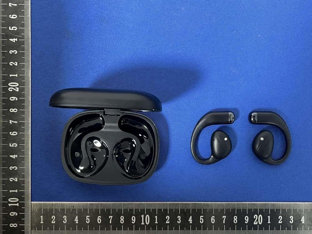
2A8TA-I86
Dec 06, 2025Open-Ear Headphones
Equipment Class
DSS - Part 15 Spread Spectrum Transmitter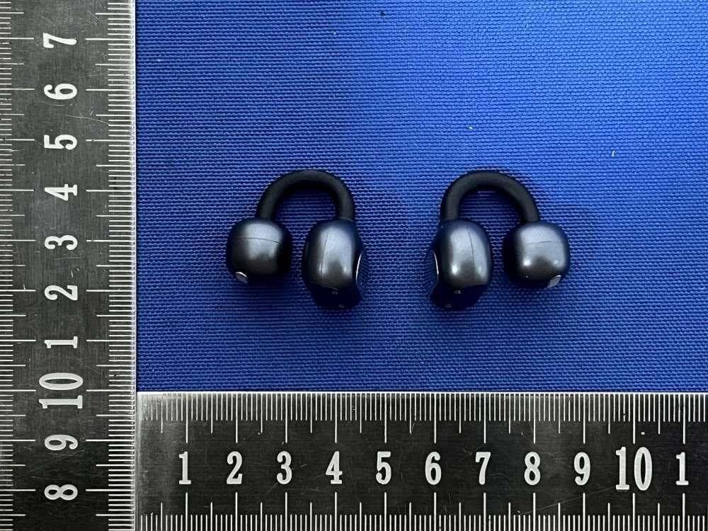
2A8TA-I78
Nov 25, 2025Wireless headphones
Equipment Class
DSS - Part 15 Spread Spectrum Transmitter2A8TAI33
Jul 02, 2024Wireless Bluetooth Earphones
Equipment Class
DSS - Part 15 Spread Spectrum Transmitter