2A8U2SWR-A002Pedestrian Sensor
Sumitomo Electric Industries, Ltd.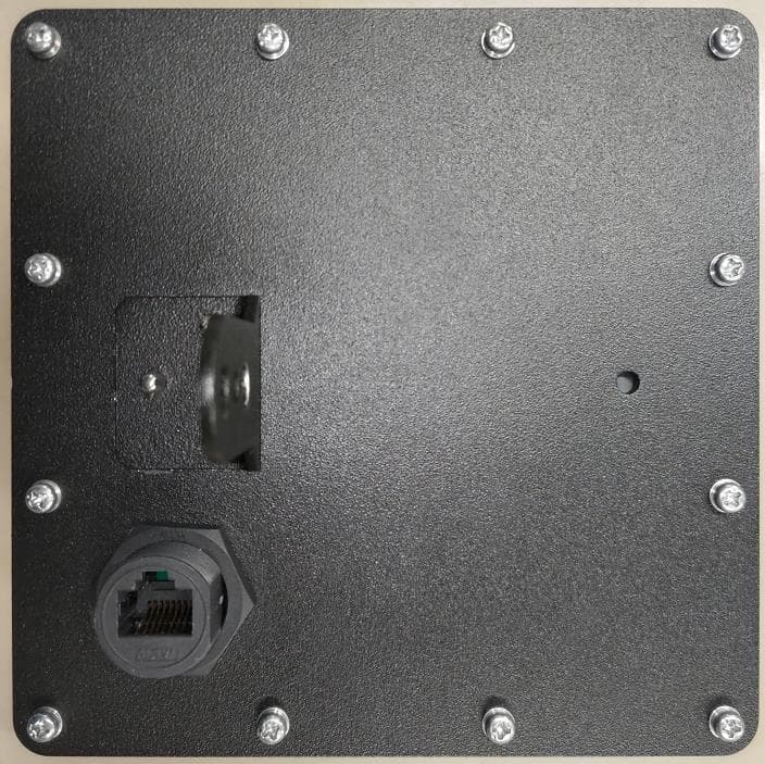
Click to zoom
Application Details
- Equipment Class
- FDS - Part 15 Field Disturbance Sensor
- Date of Grant
- Feb 13, 2024
- Application Purpose
- Original Equipment
- Date of Application
- Feb 05, 2024
- Equipment Note
- Pedestrian Sensor
- Frequency Range
- 61000.00000000 - 61500.00000000
- Country
- Japan
Documents & Files
Document Text
Text extracted from the exhibit documents filed with the FCC. Open a document above to read the original.
Users Manual
1 Sumitomo Electric Industries, Ltd. User manual for SWR-A002 2 Sumitomo Electric Industries, Ltd. CONTENT FCC Notice .................................................................................................................................................. 2 1.Introduction ................................................................................................................................................ 3 2.Specification .............................................................................................................................................. 4 3.Installation method .................................................................................................................................... 5 3.1 Installation requirement ...................................................................................................................... 5 3.2 Installation of equipment .................................................................................................................... 5 3.3 Horizontal adjustment ......................................................................................................................... 6 3.4 Vertical adjustment ............................................................................................................................. 6 4. Equipment Connection ............................................................................................................................. 7 5.Tool Operation Procedure ......................................................................................................................... 8 FCC Notice This device complies with Part 15 of the FCC Rules. Operation is subject to the following two conditions: (1)this device may not cause harmful interference, and (2) this device must accept any interference received, including interference that may cause undesired operation. FCC CAUTION Changes or modifications not expressly approved by the party responsible for compliance could void the user’s authority to operate the equipment. This transmitter must not be co-located or operated in conjunction with any other antenna or transmitter. The FCC ID for this radar is “2A8U2SWR-A002”. NOTE This equipment should be installed to a pole or other infrastructure at a height of more than 2.8 meters for keeping the radiator some distance from person’s body. It is recommended that the radar be installed at a height of 3.0m to 5m to ensure full performance. 3 Sumitomo Electric Industries, Ltd. 1.Introduction 60GHz Radar SWR-A002 is installed on the roadside and detects pedestrians based on reflected radio waves. The radar communicates with the data acquisition equipment via Ethernet and outputs detection results every 100ms. Figurer 1. System configuration Table1.Detection performance No ITEM DESCRIPTION 1 Detection Area Max. 60m x 30m (Under installation conditions with no obstructions, etc) 2 Installation Height 3 to 5m 3 Required Setbacks 1.5m or more (when the height is 3m) 4 Max. Number of Detections Up to 40 objects 5 Output Data Position, velocity, direction 6 Data Output Cycle 100ms typ RF Unit Processing and Interface Unit Data Acquisition Equipment Ethernet The Radar 4 Sumitomo Electric Industries, Ltd. 2.Specification Table 2 shows general specifications. Table2. General specifications No ITEM DESCRIPTION 1 Power Supply DC12V 2 Power Consumption Less than 10W 3 Temperature -40 to +75°C 4 Humidity Up to 95% Relative Humidity 5 Waterproofing IP65 6 Dimensions H:132mm x W:132mm x D:46mm 7 Weight Less than 1kg 8 Radar Frequency 61.0 to 61.5GHz 9 Interfaces Ethernet 100BASE-T 5 Sumitomo Electric Industries, Ltd. 3.Installation method 3.1 Installation requirement To ensure the best performance of the radar, it should be installed at a height between 3m and 5m. Also, since it is difficult to detect the area directly below the radar, it should be installed 1.5m behind the pedestrian crossing (when installed at 3m height). Figure 2. Installation requirements (at 3m height) 3.2 Installation of equipment Figure 3. Installation requirement Attach the radar to the mounting bracket and fix the cable to the arm. The Radar Max.60m Required setbacks 1.5m Installation height 3m 6 Sumitomo Electric Industries, Ltd. 3.3 Horizontal adjustment Adjust the horizontal angle so that the radar is facing the middle of the crosswalk on the other side. Figure 4. Horizontal adjustment 3.4 Vertical adjustment Attach the radar to horizontal arm using the mounting bracket. Adjust the elevation angle according to the detection area using an angle meter or similar device. Figure 5. Vertical adjustment Aim for the middle of the crosswalk on the other side. The radar will be installed to the horizontal arm via a wire and a bracket. bracket arm wire 4 ° for example Adjust the angle according to the detection area. (Using an angle meter) 7 Sumitomo Electric Industries, Ltd. 4. Equipment Connection The Radar has an external connector and supports passive PoE. Use CAT 5e cables. The Radar starts up when the power supply is connected. Table 3. External connector pin assignments Pin No. FUNCTION 1 Ethernet TX+ 2 Ethernet TX- 3 Ethernet RX+ 4 DC+12V 5 DC+12V 6 Ethernet RX- 7 0V 8 0V 8 Sumitomo Electric Industries, Ltd. 5.Tool Operation Procedure (1)Start the detection result drawing tool “AreaConfigCreator.exe”. (2)Once the tool is activated, click “Receive Start” at the lower left of the screen. Figure 6. Detection result drawing tool (3)When data is received, the detection result is displayed on the screen. Figure 7. The results of detection Click “Receive Start”
Attestation Statements
21241 S. Western Avenue, Suite 120, Torrance, CA 90501 U.S.A. TEL; +1-310-782-0227, FAX; +1-310-782-0211 Date: January 23, 2024 Federal Communications Commission Authorization and Evaluation Division 7435 Oakland Mills Road Columbia, MD 21046 RE: CFR 47 §2.911 (d)(7) FCC US Agent Letter of Attestation FCC ID: 2A8U2SWR-A002 Grantee FRN: 0032943656 To whom it may concern: FCC US Agent Contact Person: Ryosuke Kaneda Company Name: Sumitomo Electric U.S.A., Inc. FRN: 0034771840 Company Address: 21241 S. Western Avenue, Suite 120 Torrance, CA 90501 United States Email: [email protected] This letter is to confirm that we have accepted the responsibility to act as US Agent on behalf of Sumitomo Electric Industries, Ltd. (“the applicant”) for the above referenced FCC ID. We are aware of the requirements and responsibilities of the applicant’s agent for service of process as outlined in the FCC section §2.911(d)(7) and Report and Order FCC 22-84 paragraph 63. Sincerely yours, Signature: Ryosuke Kaneda Sumitomo Electric U.S.A., Inc.
External Photos
秘 -1- Sumitomo Electric Industries, Ltd. Model:SWR-A002 FCC ID:2A8U2SWR-A002 Front 秘 -2- Back 秘 -3- Right 秘 -4- Left 秘 -5- Top 秘 -6- Bottom
ID Label/Location Info
秘 -1- label size: 38 x 17 mm This label has high durability and is not easily peeled off, for the evaporated mat being laminated with polyester
Internal Photos
秘 -1- Sumitomo Electric Industries, Ltd. Model:SWR-A002 FCC ID:2A8U2SWR-A002 Front 秘 -2- Front 秘 -3- Back 秘 -4- Antenna RF Board 秘 -5- Antenna Appearance Tx1 Tx2 Tx3 Rx1 Rx2Rx3 Rx4 3mm 7mm 3mm 4mm
RF Exposure Info
Statement No. 15073959H-R1 Page 1 of 11 UL Japan, Inc. Ise EMC Lab. 4383-326 Asama-cho, Ise-shi, Mie-ken 516-0021 Japan / +81-596-24-8999 Statement for RF Exposure Statement No. 15073959H-R1 Customer Sumitomo Electric Industries, Ltd. Description of EUT Pedestrian Sensor Model Number of EUT SWR-A002 FCC ID 2A8U2SWR-A002 Issue Date February 1, 2024 Approver Ryota Yamanaka En gineer The Information provided from the customer is as follows; - Customer, Description of Equipment, Model Number of Equipment The laboratory is exempted from liability of any results affected from the above information. [FCC rule] §1.1310 Radiofrequency radiation exposure limits. The criteria listed in table 1 shall be used to evaluate the environmental impact of human exposure to radiofrequency (RF) radiation as specified in §1.1307(b), except in the case of portable devices which shall be evaluated according to the provisions of §2.1093 of this chapter. Statement No. 15073959H-R1 Page 2 of 11 UL Japan, Inc. Ise EMC Lab. 4383-326 Asama-cho, Ise-shi, Mie-ken 516-0021 Japan / +81-596-24-8999 Table 1—Limits for Maximum Permissible Exposure (MPE) Frequency range (MHz) Electric field strength (V/m) Magnetic field strength (A/m) Power density (mW/cm 2 ) Averaging time (minutes) (A) Limits for Occupational/Controlled Exposures 0.3–3.0 614 1.63 *(100) 6 3.0–30 1842/f 4.89/f *(900/f 2 ) 6 30–300 61.4 0.163 1.0 6 300–1500 f/300 6 1500–100,000 5 6 (B) Limits for General Population/Uncontrolled Exposure 0.3–1.34 614 1.63 *(100) 30 1.34–30 824/f 2.19/f *(180/f 2 ) 30 30–300 27.5 0.073 0.2 30 300–1500 f/1500 30 1500–100,000 1.0 30 f = frequency in MHz * = Plane-wave equivalent power density Note 1 to Table 1: Occupational/controlled limits apply in situations in which persons are exposed as a consequence of their employment provided those persons are fully aware of the potential for exposure and can exercise control over their exposure. Limits for occupational/controlled exposure also apply in situations when an individual is transient through a location where occupational/controlled limits apply provided he or she is made aware of the potential for exposure. Note 2 to Table 1: General population/uncontrolled exposures apply in situations in which the general public may be exposed, or in which persons that are exposed as a consequence of their employment may not be fully aware of the potential for exposure or can not exercise control over their exposure. Statement No. 15073959H-R1 Page 3 of 11 UL Japan, Inc. Ise EMC Lab. 4383-326 Asama-cho, Ise-shi, Mie-ken 516-0021 Japan / +81-596-24-8999 [About fundamental measurement (Average)] Test Procedure The test was performed based on “Procedures for testing millimeter-wave systems” of ANSI C63.10-2013. The peak power were measured with an RF detector that has a detection bandwidth that encompasses the 57-71 GHz band and has a video bandwidth of at least 10 MHz. The carrier levels were measured in the far field. The distance of the far field was calculated from follow equation. 2 2D r where r is the distance from the radiating element of the EUT to the edge of the far field, in m D is the largest dimension of both the radiating element and the test antenna (horn), in m Lambda is the wavelength of the emission under investigation [300/f (MHz)], in m Frequency WavelengthFar FieldTested EUTTestMaximumBoundaryDistance Lambda AntennaDr [GHz][mm][m][m][m][m][m] 614.90.007000.037590.037590.5750.75 Maximum Dimention The test was performed based on stages 1-4 following; Stage 1: Connect the measurement antenna for the fundamental frequency band to the mm-wave RF detector. Place the measurement antenna at a test distance that is in the far-field of the measurement antenna. Place the measurement antenna in the main beam of the EUT then maximize the fundamental emission. The maximum direction was searched under carefully since beam-widths are extremely narrow. Record the peak voltage from DSO as DSO Reading. Stage 2: Disconnect the measurement antenna from the RF input port of the instrumentation system. Connect a mm-wave source to the RF input port of the instrumentation system via a waveguide variable attenuator. The mm-wave source shall be unmodulated. Adjust the frequency of the mm-wave source to the center of the frequency range occupied by the transmitter. Adjust the amplitude of the mm-wave source and/or the variable attenuator such that the DSO indicates a voltage equal to the peak voltage recorded in Stage 1. The output level of mm-wave source at this time is recorded as SG Reading. Stage 3: Disconnect the waveguide variable attenuator from the RF input port of the instrumentation system. Without changing any settings, connect the waveguide variable attenuator to a wideband mm-wave power meter with a thermocouple detector or equivalent. Measure the power and record it as PM reading. Stage 4: Correct the peak substitution power at the input to the measurement instrument, as recorded in Stage 3, for any external gain and/or attenuation between the measurement antenna and the measurement instrument that was not included in the substitution power measurement. The test results and limit are rounded off to one decimal place, so some differences might be observed. Statement No. 15073959H-R1 Page 4 of 11 UL Japan, Inc. Ise EMC Lab. 4383-326 Asama-cho, Ise-shi, Mie-ken 516-0021 Japan / +81-596-24-8999 [Test configuration] Stage 1 EUT Test Distance: 0.75 m SGHLNAIsolatorDetectorOscciloscope MHA- 33MP A- 23MIS O - 03MD T - 04 RF c a ble MD O - 10 MC C - 67 50 Ohm Stage 2 SGTriplerIsolatorIsolatorDetectorOscciloscope MS G- 12 RF cable MFT - 02MIS O - 01MIS O - 03MD T - 04 RF c a ble MD O - 10 MC C - 55MC C - 67 50 ohm Stage 3 SGTriplerIsolatorPow er sensorPow er meter MS G- 12 RF cable MFT-02MISO-01MPSE-07 Sensor cable MP M- 01 MC C - 55 Test data : APPENDIX Test result : Pass Statement No. 15073959H-R1 Page 5 of 11 UL Japan, Inc. Ise EMC Lab. 4383-326 Asama-cho, Ise-shi, Mie-ken 516-0021 Japan / …
Text truncated - open the document above for the full version.
Test Report
Test Report No. 15073959H-R1 Page 1 of 52 UL Japan, Inc. Ise EMC Lab. 4383-326 Asama-cho, Ise-shi, Mie-ken 516-0021 Japan / +81-596-24-8999 RADIO TEST REPORT Test Report No. 15073959H-R1 Customer Sumitomo Electric Industries, Ltd. Description of EUT Pedestrian Sensor Model Number of EUT SWR-A002 FCC ID 2A8U2SWR-A002 Test Regulation FCC Part 15 Subpart C Test Result Complied Issue Date February 1, 2024 Remarks - Representative test engineer Approved by Junki Nagatomi Engineer Ryota Yamanaka Engineer CERTIFICATE 5107.02 The testing in which "Non-accreditation" is displayed is outside the accreditation scopes in UL Japan, Inc. There is no testing item of "Non-accreditation". Report Cover Page - Form-ULID-003532 (DCS:13-EM-F0429) Issue# 23.0 Test Report No. 15073959H-R1 Page 2 of 52 UL Japan, Inc. Ise EMC Lab. 4383-326 Asama-cho, Ise-shi, Mie-ken 516-0021 Japan / +81-596-24-8999 ANNOUNCEMENT REVISION HISTORY Original Test Report No.: 15073959H This report is a revised version of 15073959H. 15073959H is replaced with this report. Revision Test Report No. Date Page Revised Contents - (Original) 15073959H January 10, 2024 - 1 15073959H-R1 February 1, 2024 Deletion of "Antenna Gain" and "Steerable Antenna" from Radio Specification of SECTION 2.2. 1 15073959H-R1 February 1, 2024 Update to ANSI C63.10 version of Test Procedure in Section 3.2 and P.16, 17, 25, 29 and 33. 1 15073959H-R1 February 1, 2024 Correction of the Frequency for SECTION 4.1; From “61.128 GHz” to “61.133 GHz” (Pattern 1) From “61.360 GHz” to “61.365 GHz” (Pattern 2) 1 15073959H-R1 February 1, 2024 Addition of the “99 % Occupied bandwidth” in SECTION 4.1 and SECTION 7. 1 15073959H-R1 February 1, 2024 Correction of the Antenna size in SECTION 6 (page 17); From “0.01090 m” to “0.00700 m” 1 15073959H-R1 February 1, 2024 Deletion of LPF notation in Test configuration in SECTION 6 (page 18). 1 15073959H-R1 February 1, 2024 Addition of 99 % Occupied bandwidth table in 20 dB Bandwidth test data (page 24). 1 15073959H-R1 February 1, 2024 The following correction to EIRP(Peak) test data (page 25): - DSO Reading (RMS) value (Pattern 2: Tx 3) From “31.7” to “31.8” -Frequency From “61.128 GHz” to “61.133 GHz” (Pattern 1) From “61.360 GHz” to “61.365 GHz” (Pattern 2) 1 15073959H-R1 February 1, 2024 Deletion of the calculation under the chart in Plot data (page 30 and 34). 1 15073959H-R1 February 1, 2024 Addition of 99 % Occupied bandwidth result in Frequency Stability test data (page 35 and 39). 1 15073959H-R1 February 1, 2024 Addition of LIMS ID: 238712 in APPENDIX 2. This test report shall not be reproduced in full or partial, without the written approval of UL Japan, Inc. The results in this report appl y only to the sample tested. (Laboratory was not involved in sampling.) This sample tested is in compliance with the limits of the above re gulation. The test results in this test report are traceable to the national or international standards. This test report must not be used by the customer to claim product certification, approval, or endorsement b y the A2LA accreditation body. This test report covers Radio technical requirements. It does not cover administrative issues such as Manual or non-Radio test related Requirements. (if applicable) The all test items in this test report are conducted b y UL Japan, Inc. Ise EMC Lab. The opinions and the interpretations to the result of the description in this report are outside scopes where UL Japan, Inc. has been accredited. The information provided b y the customer for this report is identified in SECTION 1. The laboratory is not responsible for information provided by the customer which can impact the validit y of the results. For test report (s) referred in this report, the latest version (including any revisions) is always referred. Test Report No. 15073959H-R1 Page 3 of 52 UL Japan, Inc. Ise EMC Lab. 4383-326 Asama-cho, Ise-shi, Mie-ken 516-0021 Japan / +81-596-24-8999 Reference: Abbreviations (Including words undescribed in this report) A2LA The American Association for Laboratory Accreditation ICES Interference-Causing Equipment Standard AC Alternating Current IEC International Electrotechnical Commission AFH Adaptive Frequency Hopping IEEE Institute of Electrical and Electronics Engineers AM Amplitude Modulation IF Intermediate Frequency Amp, AMP Amplifier ILAC International Laboratory Accreditation Conference ANSI American National Standards Institute ISED Innovation, Science and Economic Development Canada Ant, ANT Antenna ISO International Organization for Standardization AP Access Point JAB Japan Accreditation Board ASK Amplitude Shift Keying LAN Local Area Network Atten., ATT Attenuator LIMS Laboratory Information Management System AV Average MCS Modulation and Coding Scheme BPSK Binary Phase-Shift Keying MRA Mutual Recognition Arrangement BR Bluetooth Basic Rate N/A Not Applicable BT Bluetooth NIST National Institute of Standards and Technology BT LE Bluetooth Low Energy NS No signal detect. BW BandWidth NSA Normalized Site Attenuation Cal Int Calibration Interval NVLAP National Voluntary Laboratory Accreditation Pro gram CCK Complementary Code Keying OBW Occupied Band Width Ch., CH Channel OFDM Orthogonal Frequency Division Multiplexing CISPR Comite International Special des Perturbations Radioelectriques P/M Power meter CW Continuous Wave PCB Printed Circuit Board DBPSK Differential BPSK PER Packet Error Rate DC Direct Current PHY Physical Layer D-factor Distance factor PK Peak DFS Dynamic Frequency Selection PN Pseudo random Noise DQPSK Differential QPSK PRBS Pseudo-Random Bit Sequence DSSS Direct Sequence Spread Spectrum PSD Power Spectral Density EDR Enhanced Data Rate QAM Quadrature Amplitude Modulation EIRP, e.i.r.p. Equivalent Isotropically Radiated Power QP Quasi-Peak EMC ElectroMagnetic Compatibility QPSK Quadri-Phase Shift Keying EMI ElectroMagnetic Interference RBW Resolution Band Width EN European Norm RDS Radio Data System ERP, e.r.p. Effective …
Text truncated - open the document above for the full version.
Test Setup Photos
Test Report No. 15073959H-R1 Page 46 of 52 UL Japan, Inc. Ise EMC Lab. 4383-326 Asama-cho, Ise-shi, Mie-ken 516-0021 Japan / +81-596-24-8999 APPENDIX 3: Photographs of test setup Conducted Emission Photo 1 Photo 2 Test Report No. 15073959H-R1 Page 47 of 52 UL Japan, Inc. Ise EMC Lab. 4383-326 Asama-cho, Ise-shi, Mie-ken 516-0021 Japan / +81-596-24-8999 EIRP Photo 1 Photo 2 Test Report No. 15073959H-R1 Page 48 of 52 UL Japan, Inc. Ise EMC Lab. 4383-326 Asama-cho, Ise-shi, Mie-ken 516-0021 Japan / +81-596-24-8999 Spurious Emissions (9 kHz to 30 MHz) Photo 1 Photo 2 Test Report No. 15073959H-R1 Page 49 of 52 UL Japan, Inc. Ise EMC Lab. 4383-326 Asama-cho, Ise-shi, Mie-ken 516-0021 Japan / +81-596-24-8999 Spurious Emissions (30 MHz to 1000 MHz) Photo 1 Photo 2 Test Report No. 15073959H-R1 Page 50 of 52 UL Japan, Inc. Ise EMC Lab. 4383-326 Asama-cho, Ise-shi, Mie-ken 516-0021 Japan / +81-596-24-8999 Spurious Emissions (Above 1 GHz) Photo 1 Photo 2 Test Report No. 15073959H-R1 Page 51 of 52 UL Japan, Inc. Ise EMC Lab. 4383-326 Asama-cho, Ise-shi, Mie-ken 516-0021 Japan / +81-596-24-8999 Worst Case Position Test range Horizontal Vertical Below 1 GHz X-axis X-axis 1 GHz to 10 GHz Y-axis X-axis 10 GHz to 40 GHz Y-axis Z-axis 40 GHz to 57 GHz X-axis X-axis 57 GHz to 71 GHz X-axis Y-axis 71 GHz to 110 GHz X-axis X-axis Above 110 GHz X-axis X-axis X-axis Y-axis Z-axis Test Report No. 15073959H-R1 Page 52 of 52 UL Japan, Inc. Ise EMC Lab. 4383-326 Asama-cho, Ise-shi, Mie-ken 516-0021 Japan / +81-596-24-8999 Frequency Stability Photo 1 End of Report
Contact Information
Applicant
Hideaki Shiranaga(Manager)
Technical Contact
UL Japan, Inc.Ryota Yamanaka
[email protected]81-596-24-8999
4383-326 Asama-cho, Ise-shi · Mie-ken · Japan
Test Firm
UL Japan, Inc.(Ise)Takayuki Shimada
Technical Specifications
| # | Rule Parts | Frequency Range | Power Output |
|---|---|---|---|
| 1 | 15.255 | 61.00 GHz - 61.50 GHz | 77.80 mW |