2A8VJB-2Remote Control
CM-GLO LLC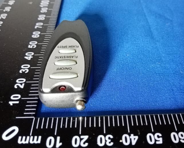
Click to zoom
Application Details
- Equipment Class
- DSC - Part 15 Security/Remote Control Transmitter
- Date of Grant
- Oct 08, 2022
- Application Purpose
- Original Equipment
- Date of Application
- Oct 08, 2022
- Equipment Note
- Remote Control
- Frequency Range
- 315.00000000 - 315.00000000
- Company
- CM-GLO LLC
- Country
- United States
Documents & Files
Document Text
Text extracted from the exhibit documents filed with the FCC. Open a document above to read the original.
Users Manual
Installation 1. Install ceiling hooks (not provided) 14.25” apart. 2. Hang the sign with the provided cable set (Fig. 1). A. Press and hold the Release Button on the gripper. B. Feed the cable into the Release Button and out the side, let go of button ensuring the cable is gripped. C. Place the provided S-hooks thru the loops at the end of the cables and attach to the top of the sign. D. Press the Release Button again on each gripper to slide the cables until the sign is level and at the desired height. E. Cut excess cable with scissors. 3. Insert the power cord into the back of the sign and plug the adapter into a grounded outlet. 4. On the back of the sign, set the power switch to the REMOTE position to control the sign via remote control. (Remote includes 27A battery; Range: 50 feet) 5. On the side of the remote control, switch the power to the ON position and press the ON or OFF button to control the sign(s). 08/2021 CAUTION - To reduce the risk of fire, electric shock or injury: • Hang signs together per the Approved Hanging Options ONLY. Other hanging configurations will affect proper power current and damage may occur. Improper installation is not covered under warranty. Follow diagrams on back side. • This product is for indoor use only. Do not use in damp or wet locations. • Not for use with light dimmer circuits. • T o reduce the likelihood of injury or damage, mount only to a mechanically sound surface. • Do not use extension cords or outlets with inadequate current carrying capacity. • It is recommended to use a surge protector. Power surges ARE NOT covered under warranty for this product. • Only use power adapter supplied with sign. • Do not handle adapter or sign with wet hands. • Disconnect power before handling or cleaning. • Do not use liquid cleaners or aerosol cleaners. Use a dry cloth for cleaning. • This product is fully assembled and ready to use. Do not attempt to disassemble or service. • Do not alter the plug or power supply cord in any way. LED SIGNS Limited 3 Year Warranty C-M Glo, LLC warrants that this product will be free from defect due to material and workmanship under normal use for a period of three (3) years and warrants the power supply for two (2) years from the date of purchase. Please retain receipt for proof of purchase. Proof of purchase is required for any warranty claim. Warranty is void if product is abused, disassembled, or exposed to atmosphere or conditions other than stated within instructions. If product fails within the specified time, contact C-M Glo at the address below for return details. Your sign will be repaired or replaced within six weeks. For Sales Outside of North America: These signs are warranted for a period of 3 years after purchase by the end user, provided the sign is installed within one year of the production date on the sticker on the back of the sign. This one year allows for transit, storage at a distributor, etc. Proof of purchase by the end user within one year of the production date will be required. C-M Glo, LLC 1201 N. 4th Street, Watertown, WI 53098 (920) 261-1000 • [email protected] DISCLAIMER OF WARRANTY All signage products manufactured by CM Global are warranted to be free from defects in material and workmanship under normal use and service, and providing that no alterations have been made to the product and that the product shall be used in accordance with printed instructions, operating temperatures, and operated in circuits of voltage stamped on the nameplate. Except as otherwise provided in this War- ranty, our obligation under this warranty shall be limited to replacing or repairing, at our option, any parts which shall be demonstrated to be defective within THREE (3) YEARS after the date of purchase by the user. Only CM Global sold transformers/power supplies may be used with CM Global signs. Any third party transformer/power supply used and not purchased through CM Global will void the product warranty. We shall, upon prompt, written notice and compliance by the user with such instructions as our Customer Service Department shall give with respect to the return of defective products or parts, correct such defect by repair or replacement of the defective part or parts. Correction in the manner provided above shall constitute a fulfillment of all of our liabilities with respect to the quality of the products. Our liability arising from or in any way connected with the products sold, the delivery or any delay with respect thereto or otherwise arising from or relating to this Warranty shall be limited exclusively, and at our sole election, to either repair or replacement of products sold refund of the purchase price. Replacement or repair of any component does not extend the warranty period of sign. This warranty does not cover misuse or abuse, unauthorized repair, alteration or disassembly by unauthorized personnel; or operation by improper voltage or current (including power surges). In no event shall CM Global be liable for any incidental, consequential, or special damages of any kind or nature whatsoever, including, but not limited to, lost profits arising from or in any way connected with this Warranty, or items sold hereunder, whether alleged to arise from breach of contract, express or implied warranty, or in tort, including, without limitation, negligence, failure to warn or strict liability. Subway Sign Model #950910 18V 5A power supply Fig. 1 Subway ® Indoor LED Signs Installation Guide Open Sign Model #970000 18V 3A power supply Choice Mark Sign Model #950900 18V 3A power supply Add-On Message Signs Does NOT include a power supply -- signs powered by the Open Sign. Hang up to 3 from each Open Sign #970001 #970002 #970003 #970004 #970005 #970006 Maximum of 3 Add-On Signs To level sign and adjust height: Press and hold Release Button to slide cable up/down Approved Hanging Options ***Always use power supply included with TOP SIGN*** Available Sign Models All signs sold separately. Hanging hook…
Text truncated - open the document above for the full version.
External Photos
Remote Control FCC ID: 2A8VJB-2 Remote B-2 External Photographs
ID Label/Location Info
Remote B-2 Label and Label location Model: Remote B-2 FCC ID: 2A8VJB-2
Internal Photos
Remote Control FCC ID: 2A8VJB-2 Remote B-2 Internal Photographs
Test Report
Antenna Spe. 1. Size as follow 2. Frequency 315MHz 3. Antenna type: integral,0dBi
Test Report
Waltek Testing Group (Shenzhen) Co., Ltd. Http://www.waltek.com.cn Page 1 of 23 TEST REPORT Reference No. ....................: WTX22X0803457W-1 FCC ID ................................: 2A8VJB-2 Applicant ...........................: CM-GLO LLC Address ..............................: 1201 N 4th Street, Watertown, WI 53098, USA Product Name ...................: Remote Control Test Model. ........................: Remote B -2 Standards ..........................: FCC Part 15.231 Date of Receipt sample ....: September 23, 2022 Date of Test........................: September 23, 2022 to October 8, 2022 Date of Issue .....................: October 8, 2022 Test Result .........................: Pass Remarks: The results shown in this test report refer only to the sample(s) tested, this test report cannot be reproduced, except in full, without prior written permission of the company. The report would be invalid without specific stamp of test institute and the signatures of compiler and approver. Prepared By: Waltek Testing Group (Shenzhen) Co., Ltd. Address: 1/F., Room 101, Building 1, Hongwei Industrial Park, Liuxian 2nd Road, Block 70 Bao'an District, Shenzhen, Guangdong, China Tested by: Reviewed By: Approved & Authorized By: Tom Wang / Project Engineer Jason Su / RF Manager Silin Chen / Manager Reference No.: WTX22X0803457W-1 Page 2 of 23 Waltek Testing Group (Shenzhen) Co., Ltd. Http://www.waltek.com.cn \ TABLE OF CONTENTS 1. GENERAL INFORMATION ...................................................................................................................................3 1.1 PRODUCT DESCRIPTION FOR EQUIPMENT UNDER TEST (EUT) ...............................................................................3 1.2 TEST STANDARDS ...................................................................................................................................................4 1.3 TEST METHODOLOGY .............................................................................................................................................4 1.4 TEST FACILITY .......................................................................................................................................................4 1.5 EUT SETUP AND TEST MODE .................................................................................................................................5 1.6 MEASUREMENT UNCERTAINTY ..............................................................................................................................5 1.7 TEST EQUIPMENT LIST AND DETAILS .....................................................................................................................6 2. SUMMARY OF TEST RESULTS ...........................................................................................................................8 3. ANTENNA REQUIREMENT ..................................................................................................................................9 3.1 STANDARD APPLICABLE .........................................................................................................................................9 3.2 TEST RESULT..........................................................................................................................................................9 4. CONDUCTED EMISSIONS .................................................................................................................................. 10 4.1 TEST PROCEDURE ................................................................................................................................................. 10 4.2 BASIC TEST SETUP BLOCK DIAGRAM ................................................................................................................... 10 4.3 ENVIRONMENTAL CONDITIONS ............................................................................................................................ 10 4.4 TEST RECEIVER SETUP ......................................................................................................................................... 10 4.5 SUMMARY OF TEST RESULTS/PLOTS .................................................................................................................... 11 4.6 CONDUCTED EMISSIONS TEST DATA .................................................................................................................... 11 5. RADIATED EMISSIONS ....................................................................................................................................... 12 5.1 STANDARD APPLICABLE ....................................................................................................................................... 12 5.2 TEST PROCEDURE ................................................................................................................................................. 13 5.3 CORRECTED AMPLITUDE & MARGIN CALCULATION ............................................................................................ 14 5.4 ENVIRONMENTAL CONDITIONS ............................................................................................................................ 14 5.5 SUMMARY OF TEST RESULTS/PLOTS .................................................................................................................... 14 6. 20DB BANDWIDTH ............................................................................................................................................... 17 6.1 STANDARD APPLICABLE ....................................................................................................................................... 17 6.1 TEST PROCEDURE ................................................................................................................................................. 17 6.2 ENVIRONMENTAL CONDITIONS .......................................................................…
Text truncated - open the document above for the full version.
Test Setup Photos
Remote Control FCC ID: 2A8VJB-2 Remote B-2 Test Setup Photos Radiated emission 30MHz~1GHz Radiated emission above 1GHz
Contact Information
Applicant
Susan Hu
Test Firm
Waltek Testing Group (Shenzhen) Co., Ltd.Jandy So
Technical Specifications
| # | Rule Parts | Frequency Range | Power Output |
|---|---|---|---|
| 1 | 15.231 | 315 MHz - 315 MHz | - |