2A8WB-MAT30Temp Module
Shenzhen Mindray Animal Medical Technology Co., Ltd.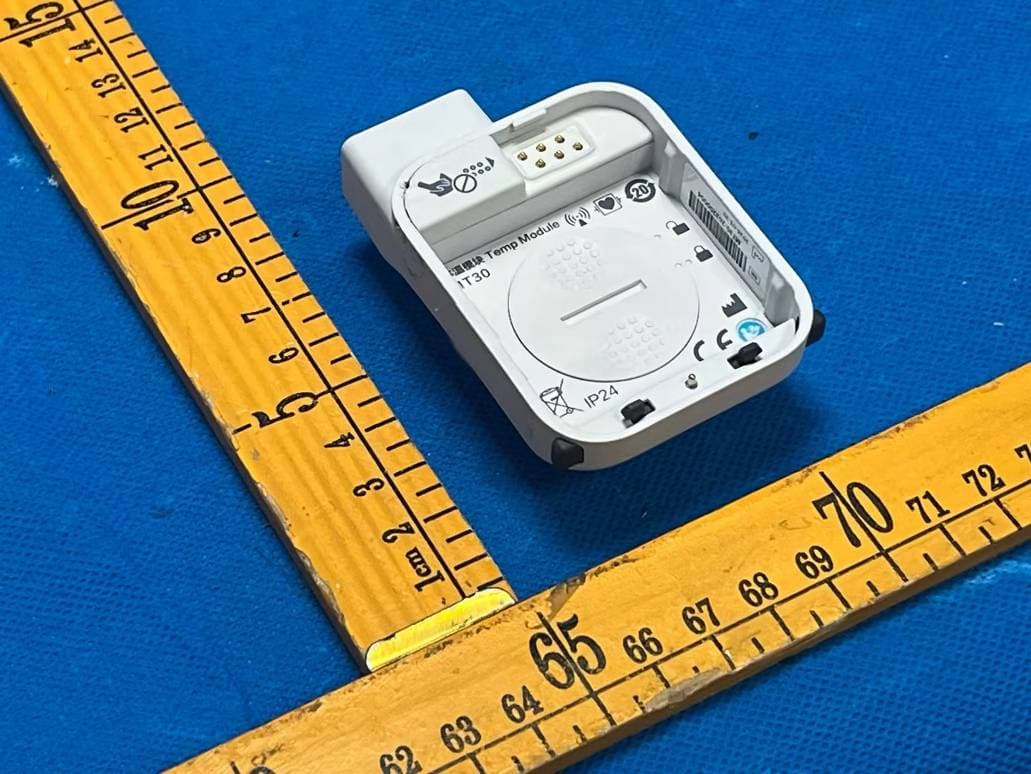
Click to zoom
Application Details
- Equipment Class
- DTS - Digital Transmission System
- Date of Grant
- Aug 28, 2026
- Application Purpose
- Original Equipment
- Equipment Note
- Temp Module
- Frequency Range
- 2402.00000000 - 2480.00000000
- Country
- China
Documents & Files
Document Text
Text extracted from the exhibit documents filed with the FCC. Open a document above to read the original.
Users Manual
Operator’s Manual Veterinary Intensive Care Cabin ViCare U7/ViCare U7L/ViCare U7R 1 ©2026 Shenzhen Mindray Animal Medical Technology Co., Ltd. All Rights Reserved. For this Operator’s Manual, the issue date is 2026-05. Intellectual Property Statement Shenzhen Mindray Animal Medical Technology Co., Ltd. (hereinafter called Mindray Animal Medical) owns the intellectual property rights to this device and this manual. This manual may refer to information protected by copyright or patents and does not convey any license under the patent rights or copyright of Mindray Animal Medical, or of others. Mindray Animal Medical intends to maintain the contents of this manual as confidential information. Disclosure of the information in this manual in any manner whatsoever without the written permission of Mindray Animal Medical is strictly forbidden. Release, amendment, reproduction, distribution, rental, adaptation, translation or any other derivative work of this manual in any manner whatsoever without the written permission of Mindray Animal Medical is strictly forbidden. is the trademark of SHENZHEN MINDRAY BIO-MEDICAL ELECTRONICS CO., LTD. in China and other countries. All other trademarks that appear in this manual are used only for informational or editorial purposes. They are the property of their respective owners. Responsibility on the Manufacturer Party Contents of this manual are subject to change without prior notice. All information contained in this manual is believed to be correct. Mindray Animal Medical shall not be liable for errors contained herein or for incidental or consequential damages in connection with the furnishing, performance, or use of this manual. Mindray Animal Medical is responsible for the effects on safety, reliability and performance of this device, only if: • all installation operations, expansions, changes, modifications and repairs of this device are conducted by Mindray Animal Medical authorized personnel; • the electrical installation of the relevant room complies with the applicable national and local requirements; and • the device is used in accordance with the instructions for use. Important! The device is veterinary use only. 2 NOTE This device must be operated by skilled/trained clinical professionals. WARNING It is important for the hospital or organization that employs this device to carry out a reasonable service/maintenance plan. Neglect of this may result in machine breakdown or personal injury. Warranty THIS WARRANTY IS EXCLUSIVE AND IS IN LIEU OF ALL OTHER WARRANTIES, EXPRESSED OR IMPLIED, INCLUDING WARRANTIES OF MERCHANTABILITY OR FITNESS FOR ANY PARTICULAR PURPOSE. Exemptions Mindray Animal Medical’s obligation or liability under this warranty does not include any transportation or other charges or liability for direct, indirect or consequential damages or delay resulting from the improper use or application of the device or the use of parts or accessories not approved by Mindray Animal Medical or repairs by people other than Mindray Animal Medical authorized personnel. This warranty shall not extend to: • Malfunction or damage caused by improper use or man-made failure. • Malfunction or damage caused by unstable or out-of-range power input. • Malfunction or damage caused by force majeure such as fire and earthquake. • Malfunction or damage caused by improper operation or repair by unqualified or unauthorized service people. • Malfunction of the instrument or part whose serial number is not legible enough. • Others not caused by instrument or part itself. 3 Contact Information Global Service Department North America Service Department Important Information • It is the customer’s responsibility to maintain and manage the device after delivery. • The warranty does not cover the following items, even during the warranty period: – Damage or loss due to misuse or abuse. – Damage or loss caused by Acts of God such as fires, earthquakes, floods, lightning, etc. – Damage or loss caused by failure to meet the specified conditions for this device, such as inadequate power supply, improper installation or environmental conditions. – Damage or loss due to use of the device outside the region where the device was originally sold. – Damage or loss involving the device purchased from a source other than Mindray Animal Medical or its authorized agents. • This device shall not be used by persons other than fully qualified and certified medical personnel. • DO NOT make changes or modifications to the software or hardware of this device. • In no event shall Mindray Animal Medical be liable for problems, damage, or loss caused by relocation, modification, or repair performed by personnel other than those designated by Mindray Animal Medical. • The purpose of this device is to provide physicians with data for clinical diagnosis. The physician is responsible for the results of diagnostic procedures. Mindray Animal Medical shall not be liable for the results of diagnostic procedures. • Important data must be backed up on external memory media. • Mindray Animal Medical shall not be liable for loss of data stored in the memory of this device caused by operator error or accidents. Shenzhen Mindray Animal Medical Technology Co., Ltd. Address: Room 702, Tower 4, YESUN Intelligent Community III, No.1301-88 Guanguang Road, Xinlan Community, Guanlan Street, Longhua District, Shenzhen 518110, P. R. China Website: www.mindrayanimal.com E-mail Address: [email protected] Tel: +86 755 33997000 Mindray Animal Medical Technology North America Co., Ltd. Address: 1200 MacArthur Blvd, Unit 302B, Mahwah, NJ 07430, USA E-mail Address:[email protected] Tel:1.800.864.5364 4 • This manual contains warnings regarding foreseeable potential dangers, but you shall also be continuously alert to dangers other than those indicated. Mindray Animal Medical shall not be liable for damage or loss resulting from negligence or ignorance of the precautions and operating instructions desc…
Text truncated - open the document above for the full version.
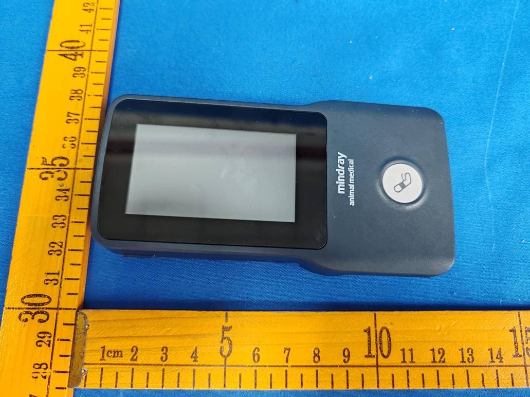
External Photos
Appendix-MAT30-Photos Reference No.: WTD25D12348210W Page 3 of 5 2. Photographs –Constructional Details 2.1. EUT – External View Model MAT30 FCC ID: 2A8WB-MAT30
Internal Photos
Appendix-MAT30-Photos Reference No.: WTD25D12348210W Page 4 of 5 2.2. EUT – Internal View Model MAT30 FCC ID: 2A8WB-MAT30 Appendix-MAT30-Photos Reference No.: WTD25D12348210W Page 5 of 5
RF Exposure Info
Waltek Testing Group Co., Ltd. http://www.waltek.com.cn Page 1 of 8 TEST REPORT Reference No. .................... : WTD25D12348210W003 FCC ID ................................ : 2A8WB-MAT30 Applicant ............................ : Shenzhen Mindray Animal Medical Technology Co., Ltd. Address .............................. : Room 702, Tower 4, YESUN Intelligent Community III, No.1301-88 Guanguang Road, Shenzhen, China Manufacturer ..................... : Shenzhen Mindray Animal Medical Technology Co., Ltd. Address .............................. : Room 702, Tower 4, YESUN Intelligent Community III, No.1301-88 Guanguang Road, Shenzhen, China Product ............................... : Temp Module Model(s). ............................ : MAT30 Brand Name ....................... : Standards........................... : FCC 47CFR Part 2 Subpart J Section 2.1091 Date of Receipt sample .... : 2025-12-29 Date of Test ....................... : 2025-12-29 to 2026-08-03 Date of Issue ...................... : 2026-08-13 Test Result ......................... : Pass Remarks: The re sults shown in this test report refer only to the sample(s) tested, this test report cannot be reproduced, except in full, without prior written permission of the company. The report would be invalid without specific stamp of test institute and the signatures of compiler and approver. Prepared By: Waltek Testing Group Co., Ltd. Address: No. 77, Houjie Section, Guantai Road, Houjie Town, Dongguan City, Guangdong, China Tel: +86-769-2267 6998 Fax: +86-769-2267 6828 Compiled by: Approved by: James Cheng/ Project Engineer Deval Qin / Designated Reviewer Reference No.: WTD25D12348210W003 Page 2 of 8 Waltek Testing Group Co., Ltd. http://www.waltek.com.cn 2. Contents Page 1 COVER PAGE ........................................................................................................................................... 1 2. CONTENTS ............................................................................................................................................... 2 3. REVISION HISTORY ................................................................................................................................. 3 4. GENERAL INFORMATION ....................................................................................................................... 4 4.1. GENERAL DESCRIPTION OF E.U.T.................................................................................................... 4 4.2. DETAILS OF E.U.T. ......................................................................................................................... 4 4.3. TEST FACILITY ................................................................................................................................ 5 4.4. SUBCONTRACTED ........................................................................................................................... 5 4.5. ABNORMALITIES FROM STANDARD CONDITIONS ................................................................................ 5 5. TEST SUMMARY ...................................................................................................................................... 6 6. RF EXPOSURE ......................................................................................................................................... 7 6.1. REQUIREMENTS .............................................................................................................................. 7 6.2. THE PROCEDURES / LIMIT ................................................................................................................ 7 6.3. MPE CALCULATION METHOD........................................................................................................... 8 6.4. RADIO FREQUENCY RADIATION EXPOSURE EVALUATION ................................................................... 8 Reference No.: WTD25D12348210W003 Page 3 of 8 Waltek Testing Group Co., Ltd. http://www.waltek.com.cn 3. Revision History Test Report No. Date of Receipt Sample Date of Test Date of Issue Purpose Comment Approved WTD25D12348210W003 2025-12-29 2025-12-29 to 2026-08-03 2026-08-13Original - Valid Reference No.: WTD25D12348210W003 Page 4 of 8 Waltek Testing Group Co., Ltd. http://www.waltek.com.cn 4. General Information 4.1. General Description of E.U.T. Product: Temp Module Model(s): MAT30 Model Description: N/A Test Sample No.: 1-1/1 Bluetooth Version: 5.4 Hardware Version: 1.0 Software Version: 01.00.04 4.2. Details of E.U.T. Operation Frequency: 2402~2480MHz Max. RF output power: LE 1M: -9.41dBm; LE 2M: -9.41dBm Modulation Technology: GFSK Antenna installation: Ceramic antenna Antenna Gain: 6.1dBi Note: #: The antenna gain is provided by the applicant, and the applicant should be responsible for its authenticity, WALTEK lab has not verified the authenticity of its information. Ratings: DC 3V CR2032 coin battery Reference No.: WTD25D12348210W003 Page 5 of 8 Waltek Testing Group Co., Ltd. http://www.waltek.com.cn 4.3. Test Facility The test facility has a test site registered with the following organizations: ISED CAB identifier: CN0013. Test Firm Registration No.: 7760A. Waltek Testing Group Co., Ltd. Has been registered and fully described in a report filed with the Industry Canada. The acceptance letter from the Industry Canada is maintained in our files. Registration number 7760A, October 15, 2016. FCC Designation No.: CN1201. Test Firm Registration No.: 523476. Waltek Testing Group Co., Ltd. EMC Laboratory has been registered and fully described in a report filed with the (FCC) Federal Communications Commission. The acceptance letter from the FCC is maintained in our files. Registration number 523476, September 10, 2019. 4.4. Subcontracted Whether parts of tests for the product have been subcontracted to other labs: Yes No If Yes, list the related test items and lab information: Test Lab: N/A Lab address: N/A Test items: N/A 4.5. Abno…
Text truncated - open the document above for the full version.
Test Report
Waltek Testing Group Co., Ltd. http://www.waltek.com.cn Page 1 of 47 TEST REPORT Referen ce No. .................... : WTD25D12348210W002 FCC ID ................................ : 2A8WB-MAT30 Applicant ............................ : Shenzhen Mindray Animal Medical Technology Co., Ltd. Address .............................. : Room 702, Tower 4, YESUN Intelligent Community III, No.1301-88 Guanguang Road, Shenzhen, China Manufacturer .................... : Shenzhen Mindray Animal Medical Technology Co., Ltd. Address ............................. : Room 702, Tower 4, YESUN Intelligent Community III, No.1301-88 Guanguang Road, Shenzhen, China Product ............................... : Temp Module Model(s). ............................ : MAT30 Brand Name ....................... : Standards........................... : FCC 47CFR Part 15.247 Date of Receipt Sample .... : 2025-12-29 Date of Test ....................... : 2025-12-29 to 2026-08-03 Date of Issue ...................... : 2026-08-13 Test Result ......................... : Pass Remarks: The re sults shown in this test report refer only to the sample(s) tested, this test report cannot be reproduced, except in full, without prior written permission of the company. The report would be invalid without specific stamp of test institute and the signatures of compiler and approver. Prepared By: Waltek Testing Group Co., Ltd. Address: No. 77, Houjie Section, Guantai Road, Houjie Town, Dongguan City, Guangdong, China Tel: +86-769-2267 6998 Fax: +86-769-2267 6828 Compiled by: Approved by: James Cheng / Project Engineer Deval Qin / Designated Reviewer Reference No.: WTD25D12348210W002 Page 2 of 47 Waltek Testing Group Co., Ltd. http://www.waltek.com.cn 2 Contents Page 1 COVER PAGE ........................................................................................................................................... 1 2 CONTENTS ............................................................................................................................................... 2 3 REVISION HISTORY ................................................................................................................................. 3 4 GENERAL INFORMATION ....................................................................................................................... 4 4.1 General Description of E.U.T. ....................................................................................................... 4 4.2 Details of E.U.T. ............................................................................................................................ 4 4.3 Channel List .................................................................................................................................. 4 4.4 Test Facility ................................................................................................................................... 5 4.5 Subcontracted ............................................................................................................................... 5 4.6 Abnormalities from Standard Conditions ...................................................................................... 5 4.7 Test Mode ..................................................................................................................................... 5 5 TEST SUMMARY ...................................................................................................................................... 6 6 EQUIPMENT USED DURING TEST ......................................................................................................... 7 6.1 Equipments List ............................................................................................................................ 7 6.2 Description of Support Units ......................................................................................................... 8 6.3 Measurement Uncertainty ............................................................................................................ 8 6.4 Test Equipment Calibration .......................................................................................................... 8 7 RADIATED EMISSIONS ........................................................................................................................... 9 7.1 EUT Operation .............................................................................................................................. 9 7.2 Test Setup .................................................................................................................................. 10 7.3 Spectrum Analyzer Setup ........................................................................................................... 11 7.4 Test Procedure ........................................................................................................................... 12 7.5 Corrected Amplitude & Margin Calculation ................................................................................ 12 7.6 Summary of Test Results ........................................................................................................... 13 8 CONDUCTED SPURIOUS EMISSIONS ................................................................................................. 29 8.1 Test Procedure ........................................................................................................................... 29 8.2 Test Result .................................................................................................................................. 30 9 BAND EDGE MEASUREMENT .............................................................................................................. 36 9.1 Test Produce .............................................................................................................................. 36 9.2 Test Result ......................................................…
Text truncated - open the document above for the full version.
Test Report
1 AB-W01_V02 SMD Antenna Specifications 2.4 G/5G WIFI band antenna Model: AB-W01 Manufacturer: Shenzhen Etheta Communication Technology Co., LTD. 2 AB-W01_V02 Features: 1. Size: 8.0 X 3.0 X 1.0 mm 2. Low energy loss, high efficiency antenna. 3. High stability in case of temperature and humidity changes. Application: 1. 2.4 G/5G WIFI band. 2. Other wireless applications that work in the 2.4 G or 5G frequency band. Structure: Size Three views Symb ol Dimension s in mm L 8.0±0.1 w 3.0±0.1 T 1.0±0.1 a 0.6±0.1 1. Antenna signal pin 2. Antenna fixed pin 3. Patch Orientation Markers 3 AB-W01_V02 Electrical characteristics: AB-W01 Specification Operating frequency range Working Frequency 2400 -2500 MHz, 5200 -6000 MHz Impedance Impedance 50Ω Gain Gain dBi 6.1dBi (2.45 GHz), 3.67dBi (5.5Ghz) Standing wave ratio (VSWR) <2 Operating Temperature Operation Temperature -40°C~+85°C Allowable power Power Capacity 3W The operating frequency of the antenna needs to be debugged by using impedance matching devices.. Design of antenna pads and cabling: Design Dimension s 4 AB-W01_V02 Matching device value Series component Series 1 0Ω Parallel device Shunt 1 NC Series component Series 2 0Ω 5 AB-W01_V02 Characteristic s of Antenna S11 Antenna VSWR Feature Efficiency and radiation diagram (PCB thickness of the DEMO board 1.0 mm): The performance of efficiency, radiation diagram and gain are based on the test board design. The specification and feature test data of the AB-W01 antenna is based on the size of the test PCB and the test direction shown in the following figure. The following data is tested in the ETS 3D microwave dark chamber.. + Z X Y 6 AB-W01_V02 Gain and efficienc y Bandwidth: 2.4 G -2 .5 GHz Bandwidth 5.2 G -5 .8 GHz Peak gain Peak Gain 6.1dBi 3.67dBi In-band average gain Average Gain across the band 5.7dBi 2.63dBi In-band gain range Gain Range across the band 5.5dBi~6.1dBi 1.33dBi~3.67dBi Peak efficiency (Peak Efficiency) 82.5% 62.4% In-band average efficiency Average Efficiency across the band 79% 51% In-band efficiency range Efficiency Range across the band 74.8%~82.5% 30.77%~62.4% Theta @2.45 GHz Phi @2.45 GHz 7 AB-W01_V02 Total @2.45 GHz Theta @5.5 GHz Phi @5.5 GHz Total @5.5 GHz 8 AB-W01_V02 Welding conditions: Typical reliable and non-destructive welding specifications are shown in the following figure: 9 AB-W01_V02 Packaging: Plastic Carrier Specifications in :mm Index Ao Bo Ko T W Dimension (mm) 3.3±0.1 8.4±0.1 1.3±0.1 0.3±0.05 16.0±0.3 Index E F P P0 P2 Dimension (mm) 1.75±0.1 7.0±0.1 8.0±0.1 4.0±0.1 2.0±0.1 Reel size: Index A B C Dimension(mm) 330 100 13.5 Standard quantity: 2000 PCS/trays. 10 AB-W01_V02 Storage environment: The product should be stored under the following conditions: Carousel Storage Temperature: -10 °C~+40°C (non-antenna operating temperature) Storage Humidity of Material Tray: Do not touch corrosive gases, such as sulfur, chlorine or acid, in the place where 30% to 70% Relative Humidity% (non- antenna operating humidity) of the product is placed. The product should be placed in a tool box and protected from moisture and dust. The product should be stored in the warehouse and protected from heat, vibration and direct sunlight. The product should be stored under closed conditions.
Test Setup Photos
Appendix-MAT30-Photos Reference No.: WTD25D12348210W Page 1 of 5 1. Test Setup photos Model MAT30 FCC ID: 2A8WB-MAT30 1.1 Photograph – Radiated Emissions For 9kHz-30MHz Test Site 2# For 30MHz-1000MHz Test Site 2# Appendix-MAT30-Photos Reference No.: WTD25D12348210W Page 2 of 5 For Above 1GHz Test Site 1#
Contact Information
Applicant
Guangjie Wang(Product Verification Engineer)
[email protected]Fax: -
Technical Contact
FCC US Agent, LLCTim Payne
3722 Illinois Avenue, · Saint Charles, 60174 · United States
Test Firm
WALTEK TESTING GROUP CO., LTD.Joy Zhou
Technical Specifications
| # | Rule Parts | Frequency Range | Power Output |
|---|---|---|---|
| 1 | 15C | 2.40 GHz - 2.48 GHz | 100.00 µW |
Other Applications from Shenzhen Mindray Animal Medical Technology Co., Ltd.
2A8WB-MAB30
Sep 14, 2026NIBP Module
Equipment Class
DXX - Part 15 Low Power Communication Device Transmitter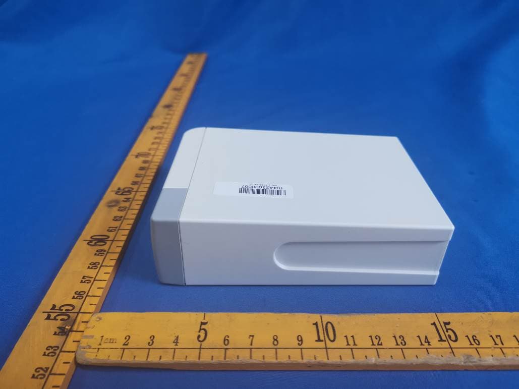
2A8WB-R20
Sep 07, 2026Receiver
Equipment Class
DXX - Part 15 Low Power Communication Device Transmitter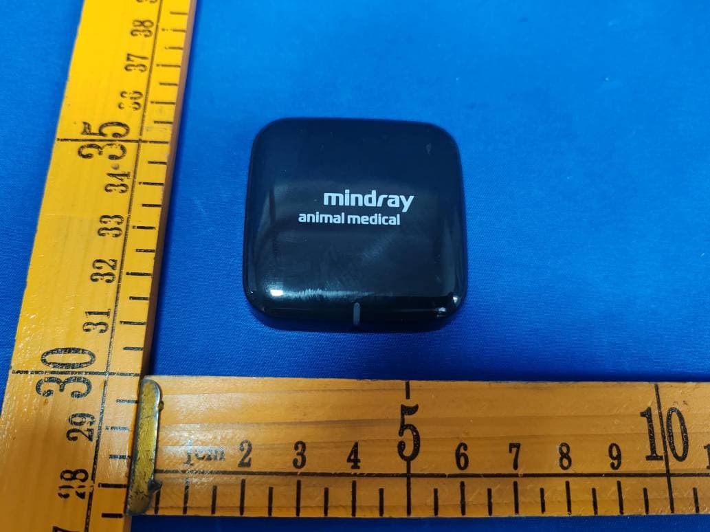
2A8WB-MAE30
Sep 01, 2026ECG Module
Equipment Class
DXX - Part 15 Low Power Communication Device Transmitter
2A8WB-LABH6
Nov 17, 2025Animal-Dedicated Hematology Analyzer (Life Science)
Equipment Class
DXX - Part 15 Low Power Communication Device Transmitter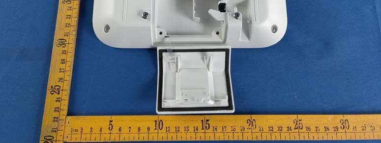
2A8WB-AP06
Oct 08, 2023Wireless access point
Equipment Class
TNB - Licensed Non-Broadcast Station Transmitter