2A8ZZDGWTM03Wearable Thermometer
Shenzhen degree electronic co.LTD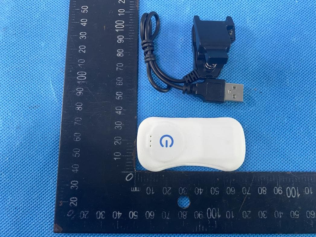
Click to zoom
Application Details
- Equipment Class
- DTS - Digital Transmission System
- Date of Grant
- Nov 07, 2022
- Application Purpose
- Original Equipment
- Date of Application
- Nov 07, 2022
- Equipment Note
- Wearable Thermometer
- Frequency Range
- 2402.00000000 - 2480.00000000
- Country
- China
Documents & Files
Document Text
Text extracted from the exhibit documents filed with the FCC. Open a document above to read the original.
Users Manual
Product name: Wearable Thermometer Model:T3M FCC ID:2A8ZZDGWTM03 FCC WARNING: This device complies with part 15 of the FCC Rules. Operation is subject to the following two conditions: (1) this device may not cause harmful interference, and (2) this device must accept any interference received, including interference that may cause undesired operation. Any changes or modifications not expressly approved by the party responsible for compliance could void the user's authority to operate the equipment. NOTE: This equipment has been tested and found to comply with the limits for a Class B digital device, pursuant to Part 15 of the FCC Rules. These limits are designed to provide reasonable protection against harmful interference in a residential installation. This equipment generates, uses and can radiate radio frequency energy and, if not installed and used in accordance with the instructions, may cause harmful interference to radio communications. However, there is no guarantee that interference will not occur in a particular installation. If this equipment does cause harmful interference to radio or television reception, which can be determined by turning the equipment off and on, the user is encouraged to try to correct the interference by one or more of the following measures: -- Reorient or relocate the receiving antenna. -- Increase the separation between the equipment and receiver. -- Connect the equipment into an outlet on a circuit different from that to which the receiver is connected. -- Consult the dealer or an experienced radio/TV technician for help. The device has been evaluated to meet general RF exposure requirement. The device can be used in portable exposure condition without restriction. Introduction The Nuvomed smart thermometer can be used to monitor and record temperature continuously. The device transfer data to smart phone via Bluetooth. The function includes remote monitor, fever alert, data share. Temperature measuring range: 68F- 122 F (20C- 50C) Bluetooth transmission range: upto 33Ft Package includes ●Thermometer ● user manual ●USB cord ●double-side adhesive Directions for use APP download Scan QR code or search “Nuvomed smart thermometer” in the App store for iPhones and Google Play Store for Android Phones. Download and install the Nuvomed Smart Thermometer app. System requirements: IOS 8.0 and above or Android 4.4 and above 1. Register and sign in. For the first time using the app, register and fill in your personal information Using the Thermometer 1.Click the “◎” button once, the indicator light will flash blue 2.Tear off the protective film on both sides of the adhesive tape, align the edges on the back of the thermometer, and gently stick-on. How to Measure temperature 1. Put the thermometer close to the mobile phone and enter the app interface. If it is measured for the first time, please create a personal profile for your thermometer. 2.Turn on the Bluetooth of mobile phone. click "+" in the upper right corner on the APP, search T3M Bluetooth for pairing. 2. once the pairing is succeeded, click the start button (Android need), and the interface will display the temperature. Once paired you can rename(**renaming depends on the model of the thermometer**) the device accordingly. If you need to add more devices you can add it by Clicking Add Equipment and then renaming accordingly so you can have separate devices for each user. Note: You can pair only one device at a time Turning off the Thermometer 1.Click "stop " on the app interface 2.Remove the thermometer, long press "◎" for 3 seconds, the blue indicator light goes out, and the device is off. How to charge the thermometer 1.When the thermometer power is running low, the app will send a low power reminder, and the thermometer power information can be viewed on the app. 2.Charging: Align with the charging column and clamp the thermometer, red indicator is on during charging, green indicator is on after charging is complete. It takes about 2 hours to fully charge. Indicator and warning tone Summary of indicator light and warning tone Thermometer Indicator Directive content Blue indicator Thermometer is on Red indicator Thermometer is charging Green indicator Charging complete Cellphone Alarm Sound and Vibration Bluetooth connection interrupted Temperature is too high or too low Thermometer power running off Technical parameters Product name Wearablethermometer model T3M Dimensions 3.11”x 1.378”0.157” Inches weight 0.0132 Lbs battery DC3.7V(polymer lithium-ion battery) Measuring range 33Ft accuracy -4°F~86°F ±32.54°F, 86°F~98.6°F ±32.6°F, 98.6°F~105.8°F ±32.18°F, 105.8°F~122°F ±32.36°F Measuring unit °C/°F Measuring range -4°F~122°F Battery life Charge-discharge 300 times Other functions 1. Report: click temperature history on mine page to view historical measurement data. 2. Alarm temperature setting: click device setting on mine page to set the high and low temperature alarm temperature. Use attention points 1. Please keep the surface clean before use. 2. Keep the thermometer tight fit the test point, , otherwise it will affect the accuracy of temperature data. 3.When measuring, try to keep the thermometer and the mobile phone clear of large obstacles, otherwise it will affect the effective transmission distance of Bluetooth. 4.Please do not bend and squeeze the thermometer. If the shell is broken, please stop using. Troubleshooting problem Possible reason solution Cannot start thermometer 1. Battery is too low. 2. Thermometer is broken. 1. Charge the thermometer 2.Check whether the. thermometer show traces of damage. If so, please replace the thermometer. Cannot connect to app 1. Therm ometer is off. 2. Blueto oth has not been turned on the Cellphone. 3. The phone is too far from the thermometer. 4. Therm ometer is broken. 1. Turn on the thermometer. 2. Verify that the phone’s Bluetooth has been turned on. 3.Put the phone next to the thermometer or adjust the location of the thermometer. 4.Replace the t…
Text truncated - open the document above for the full version.
External Photos
ATTACHMENT PHOTOGRAPHS OF EUT Photo 1 Photo 2 Photo 3 Photo 4 Photo 5 Photo 6 Photo 7 Photo 8
ID Label/Location Info
(Engraved on the metal sheet by laser engraving process)
Internal Photos
Photo 9 Photo 10 Ant Photo 11 Photo 12 Photo 13 Photo 14
RF Exposure Info
FCC ID: 2A8ZZDGWTM03 Portable device According to §15.247(e)(i) and §1.1307(b)(1), systems operating under the provisions of this section shall be operated in a manner that ensures that the public is not exposed to radio frequency energy level in excess of the Commission’s guidelines. According to KDB447498 D01 General RF Exposure Guidance V06 The 1-g SAR and 10-g SAR test exclusion thresholds for 100 MHz to 6 GHz at test separation distances ≤ 50 mm are determined by: [(max. power of channel, including tune-up tolerance, mW)/(min. test separation distance, mm)]·[√f(GHZ)] ≤ 3.0 for 1-g SAR and ≤ 7.5 for 10-g extremity SAR, where: • f(GHZ) is the RF channel transmit frequency in GHz • Power and distance are rounded to the nearest mW and mm before calculation • The result is rounded to one decimal place for comparison When the minimum test separation distance is < 5 mm, a distance of 5 mm is applied to determine SAR test exclusion. Antenna Type: Ceramic antenna Antenna Gain:3.74 dBi BLE(1M) Modulation Channel Freq. (GHz) Conduct ed power (dBm) Conducte d power (mW) Tune-up power (dBm) Max tune-up power (dBm) Max tune-up power (mW) Distance (mm) Result calculatio n 1g SAR Exclusion threshold SAR test exclusion 2.4022.7731.8942±13.01.995<50.618473.00YES 2.4401.3851.3762±13.01.995<50.623343.00YES 2.4802.3911.7342±13.01.995<50.628433.00YES GFSK Conclusion: For the max result : 0.62843≤ 3.0 for 1-g SAR, No SAR is required. Signature: Date: 2022-10-21 NAME AND TITLE (Please print or type): Alex /Manager COMPANY (Please print or type): Shenzhen NTEK Testing Technology Co., Ltd./ 1/F, Building E, Fenda Science Park, Sanwei Community, Xixiang Street Bao’an District, Shenzhen 518126 P.R. China
Test Report
OA-C07 Specification OA-C07_V01 1 SMDAntena Specification OverAir® SMD Antena Series RoHSCompliant PN:OA-C07 2.4GHz ISM band antenna OA-C07 Specification OA-C07_V01 2 Characteristic 1. Size only 3.5X1.7 X 1.2 mm3 small size SMD patch antenna. 2. Low energy loss, high antenna efficiency. 3. It has high stability when the temperature and humidity change. Application 1. Application of 2.4GHz ISM Band Antenna. 2. Bluetooth, ZigBee, Wireless applications, Smart Home applications, etc. 3. WIFI (2.4G only). Structure Size OA-C07 Specification OA-C07_V01 3 Electrical specification OA-C07 Antenna welding plate design size Working Frequency The initial frequency(GHz) Band Width Gain(dBi) Impedance VSWR Operation Temperature Power Capacity 2450±50MHz 2.9GHz >100MHz 50Ω 3.74(peak) <2 -40°C~+95°C 3W Specification OA-C07 Specification OA-C07_V01 4 Antenna test on test board(thickness of plate1.0mm) AntennaeS11Character OA-C07 Specification OA-C07_V01 5 OA-C07 Specification OA-C07_V01 6 Efficiency and radiation map The performance of efficiency, radiation diagram, gain and so on is based on the design of test board. The test data of the specification and characteristics of the 0A-C07 antenna are based on the size of the PCB board and the test direction shown in the following figure. The following data are tested in ETS 3 D microwave anechoic chamber. OA-C07 Specification OA-C07_V01 7 Welding condition The typical welding specification for reliable loss is shown in the following figure: OA-C07 Specification OA-C07_V01 8 Plastic carrier tape specification (Units:mm) Reel size OA-C07 Specification OA-C07_V01 9 Index A B C Dimension(mm) 300 100 13.5 Denominator volume:300PCS/dish Storage environment The following conditions should be met when the product is stored: 1. Temperature:-10°C~+40°C. 2. Humidity:30% ~ 70% relative humidity. 3. Do not contact corrosive gases, such as sulfur, where the product is placed. Chlorine or acid may cause the electrode oxidation of the product to cause the weldability to deteriorate. 4. The product should be placed in the toolbox and avoid the influence of moisture and dust. 5. The products should be stored in the warehouse and avoid heat, vibration and direct sunlight. 6. Products should be stored in closed conditions.
Test Report
Report No.: S22101304501001 Version.1.3 Page 1 of 46 RADIO TEST REPORT FCC ID: 2A8ZZDGWTM03 Product: Wearable Thermometer Trade Mark: N/A Model No.: T3M Family Model: N/A Report No.: S22101304501001 Issue Date: Oct 21. 2022 Prepared for Shenzhen degree electronic co.LTD 508,Bldg B,getailong comprehensive bldg,no.227,bulong road,maantang community,bantian St,longgang Dist,Sz City, China Prepared by Shenzhen NTEK Testing Technology Co., Ltd. 1/F, Building E, Fenda Science Park, Sanwei Community, Xixiang Street Bao’an District, Shenzhen 518126 P.R. China Tel. 400-800-6106, 0755-2320 0050, 0755-2320 0090 Website: http://www.ntek.org.cn Report No.: S22101304501001 Version.1.3 Page 2 of 46 TABLE OF CONTENTS 1 TEST RESULT CERTIFICATION ...................................................................................................................... 3 2 SUMMARY OF TEST RESULTS ......................................................................................................................... 4 3 FACILITIES AND ACCREDITATIONS ............................................................................................................. 5 3.1 FACILITIES..................................................................................................................................................... 5 3.2 LABORATORY ACCREDITATIONS AND LISTINGS ................................................................................. 5 3.3 MEASUREMENT UNCERTAINTY ............................................................................................................... 5 4 GENERAL DESCRIPTION OF EUT .................................................................................................................. 6 5 DESCRIPTION OF TEST MODES ..................................................................................................................... 8 6 SETUP OF EQUIPMENT UNDER TEST ........................................................................................................... 9 6.1 BLOCK DIAGRAM CONFIGURATION OF TEST SYSTEM ....................................................................... 9 6.2 SUPPORT EQUIPMENT............................................................................................................................... 10 6.3 EQUIPMENTS LIST FOR ALL TEST ITEMS .............................................................................................. 11 7 TEST REQUIREMENTS .................................................................................................................................... 13 7.1 CONDUCTED EMISSIONS TEST ............................................................................................................... 13 7.2 RADIATED SPURIOUS EMISSION ............................................................................................................ 16 7.3 6DB BANDWIDTH ....................................................................................................................................... 25 7.4 DUTY CYCLE ............................................................................................................................................... 26 7.5 PEAK OUTPUT POWER .............................................................................................................................. 28 7.6 POWER SPECTRAL DENSITY ................................................................................................................... 29 7.7 CONDUCTED BAND EDGE MEASUREMENT......................................................................................... 31 7.8 SPURIOUS RF CONDUCTED EMISSIONS................................................................................................ 32 7.9 ANTENNA APPLICATION .......................................................................................................................... 33 8 TEST RESULTS ................................................................................................................................................... 34 Report No.: S22101304501001 Version.1.3 Page 3 of 46 1 TEST RESULT CERTIFICATION Applicant’s name ......................... : Shenzhen degree electronic co.LTD Address ....................................... : 508,Bldg B,getailong comprehensive bldg,no.227,bulong road,maantang community,bantian St,longgang Dist,Sz City, China Manufacturer's Name .................. : Shenzhen degree electronic co.LTD Address ....................................... : 508,Bldg B,getailong comprehensive bldg,no.227,bulong road,maantang community,bantian St,longgang Dist,Sz City, China Product description Product name .............................. : Wearable Thermometer Model and/or type reference ...... : T3M Family Model ............................... : N/A Test Sample Number................: S221013045003 Measurement Procedure Used: APPLICABLE STANDARDS APPLICABLE STANDARD/ TEST PROCEDURE TEST RESULT FCC 47 CFR Part 2, Subpart J FCC 47 CFR Part 15, Subpart C ANSI C63.10-2013 KDB 558074 D01 15.247 Meas Guidance v05r02 Complied This device described above has been tested by Shenzhen NTEK Testing Technology Co., Ltd., and the test results show that the equipment under test (EUT) is in compliance with the FCC requirements. And it is applicable only to the tested sample identified in the report. This report shall not be reproduced except in full, without the written approval of Shenzhen NTEK Testing Technology Co., Ltd., this document may be altered or revised by Shenzhen NTEK Testing Technology Co., Ltd., personnel only, and shall be noted in the revision of the document. The test results of this report relate only to the tested sample identified in this report. Date of Test : Oct 13. 2022 ~ Oct 21. 2022 Testing Engineer : (Susan Li) Authorized Signatory : (Alex Li) Report No.: S22101304501001 Version.1.3 Page 4 of 46 2 SUMMARY OF TEST RESULTS FCC Part15 (15.247), Subpart C Standard Section Test Item Verdict Remar…
Text truncated - open the document above for the full version.
Test Setup Photos
Radiated Measurement Photos AC Conducted Measurement Photos
Contact Information
Applicant
Mingdeng Zhao
Test Firm
Shenzhen NTEK Testing Technology Co., Ltd.Alex Li
[email protected]+86-755-6115-9384
Technical Specifications
| # | Rule Parts | Frequency Range | Power Output |
|---|---|---|---|
| 1 | 15C | 2.40 GHz - 2.48 GHz | 1.89 mW |