2A93S-SMARTTIPSmart Crutch Tip
ComeBack Mobility,INC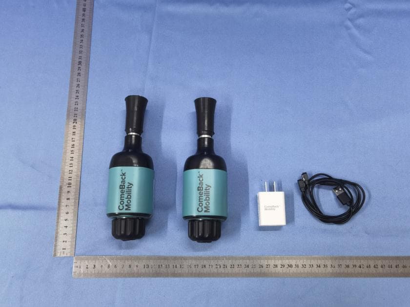
Click to zoom
Application Details
- Equipment Class
- DTS - Digital Transmission System
- Date of Grant
- Jul 23, 2023
- Application Purpose
- Original Equipment
- Date of Application
- Jul 23, 2023
- Equipment Note
- Smart Crutch Tip
- Frequency Range
- 2402.00000000 - 2480.00000000
- Company
- ComeBack Mobility,INC
- Country
- United States
Documents & Files
Document Text
Text extracted from the exhibit documents filed with the FCC. Open a document above to read the original.
Users Manual
1 | ComeBack Mobility™ Version 2.2.0 Revision A1 Print Date: Feb 03. 2023 08:54:46 AM Contents Contents 1 1. Introduction 3 1.2. Conventions 3 1.3. Why should I follow this manual? 3 1.4. Intended Use 3 1.5. Contraindications 4 1.6. Warnings and Precautions 4 1.6.1 Warnings 4 1.6.2. Precautions 4 1.7. Definitions 5 1.8. Weight-Bearing & Activity Tracking 7 1.8.1. Objective Assessment 7 1.8.2. Walking Aids 7 1.9. Device Description 7 2. Patient App Installation & Operation 8 2.1. App Download 8 2.2. Initial Connect 9 2.3. Smartphone Notifications 10 2.4. Deep Sleep Mode 11 2.5. General Screen Instruction (App Version 2.2.0) 12 3. Smart Crutch Tips Installation & Operation 13 3.1. Smart Crutch Tips Components 13 3.2. Smart Crutch Tips Mounting 13 3.3. Daily Walking With Smart Crutch Tips 14 3.3.1. Light Indications for Each Step 15 3.4. Charging The Smart Crutch Tips 16 3.4.1. Precautions for charging the device 16 3.4.2. Charging the device 16 3.4.3. Battery Indications 17 4. Care & Maintenance 18 4.1. Checklist to ensure correct daily work 18 4.2. Cleaning Instruction 18 4.3. Storage and Handling 18 4.4. Disposal 18 4.5. Expected service life 19 4.6. Return Procedure 19 4.6.1. The following items MUST be returned 19 4.7. Accessories 20 5. Troubleshooting 21 6. Appendices 24 6.1.1. Appendix: Light Indications 24 2 | ComeBack Mobility™ Version 2.2.0 Revision A1 Print Date: Feb 03. 2023 08:54:46 AM 6.1.2. Power-saving mode 24 6.1.3. Battery Charge Level 24 6.1.4. Tips are faulty (out of order) 24 6.2 Appendix: Smart Crutch Tips Specifications 24 6.3. Appendix: Walking Aids compatible with Smart Crutch Tips 26 6.4. Appendix: The App Installation for iOS or Android 27 6.4.1. Install the ComeBack Mobility Patient App via SMS from your doctor 27 6.4.2. Install the iOS ComeBack Mobility Patient App 28 6.4.3. Install the Android ComeBack Mobility Patient App 28 6.5. Safety Information 29 6.5.1. FCC Statement 29 6.5.2. Interference statement 29 6.5.3. Wireless notice 29 3 | ComeBack Mobility™ Version 2.2.0 Revision A1 Print Date: Feb 03. 2023 08:54:46 AM 1. Introduction ComeBack Mobility™ is the Weight-Bearing Real-time Feedback Service that monitors your post-recovery rehabilitation by measuring the objective weight you put on the affected leg in the clinic and at home. 1.1. Contact Information For additional information, including safety, difficulties in proper usage, damage, or loss of components, please contact ComeBack Mobility Customer Support. You may call and/or SMS/text at the following number: (929) 877-2383. Also, email us at [email protected]. . 1.2. Conventions The following conventions are used in this manual: ● A WARNING highlights a safety-related issue. ALWAYS comply with this information to prevent injury. ● A PRECAUTION highlights a product reliability issue. ALWAYS comply with this information to avoid product damage. ● A NOTE clarifies procedural information. ● A MEANING explains the Iight Indications 1.3. Why should I follow this manual? This manual contains information to ensure this product's safe, effective, and compliant use. Keep and consult the terms and conditions set forth by this manual as necessary. Failure to properly position the device will compromise the performance and lead to inaccurate results. Adherence to a weight-bearing program is a primary determinant of treatment success. A weight-bearing tracking service ensures your rehabilitation's objective progress and detects non-adherence early on. Otherwise, non-adherence may reduce functional abilities or a lower quality of life. 1.4. Intended Use The Smart Crutch Tips™ is intended to measure the weight applied to the affected limb during rehabilitation as an attachment to crutches or cane. The device alerts the patient and therapist with visual and voice notifications if the weight exceeds or does not reach a pre-determined level. ComeBack Mobility™ produces objective monitoring of gait outcomes using accurate weight analysis. All information is sent to the patient's smartphone in the CBM Patient App. You can track in real-time the load, the progress of rehabilitation, and the number of steps that need to be taken. 4 | ComeBack Mobility™ Version 2.2.0 Revision A1 Print Date: Feb 03. 2023 08:54:46 AM 1.5. Contraindications Age and body mass are common contraindications to Smart Crutch Tips use. The device is NOT suitable for people weighing <88 lb and >308 lb (<40 kg and >160 kg). Generally, children need to be at least seven years old to manage crutch navigation safely. Additionally, any musculoskeletal or neurological condition that reduces mobility, strength, or sensation can be a contraindication to crutch tips' short-term or long-term use. ComeBack Mobility Smart Crutch Tips SHOULD NOT be used in cases of ● Activity limitations due to medical disorders, medication, or emotional conditions. ● Vascular insufficiencies or infection. ● Severe cognitive disabilities. 1.6. Warnings and Precautions ComeBack Mobility Service monitors weight applied on the affected leg during the motion and provides visual and voice feedback via the ―ComeBack Mobility – Patient‖ App. Smart Crutch Tips will not prevent or reduce injury. Proper rehabilitation and activity modification are also essential to a safe treatment program. Therefore, if you feel pain or discomfort while using the device, you should stop using it immediately and consult a physician and/or medical provider. 1.6.1 Warnings ● The Smart Tips INCREASE THE HEIGHT of the crutch or cane 4.25’’ inches when mounted on crutches or cane. Make corresponding adjustments to accommodate the total height of crutches with tips is comfortable. See 6.3. Appendix: Walking Aids compatible with Smart Crutch Tips. ● NEVER modify, service, or repair the device. It can affect the function of the device. ● NEVER immerse the Smart Tips in water or any liquids. It causes permanent damage or stops functioning. ● DO NOT use Smart Tips on sand, dirt, or soft surfaces. ● DO NOT st…
Text truncated - open the document above for the full version.
Attestation Statements
ComeBack Mobility,INC Covered Equipment Certification Attestation Letter Federal Communications Commission Authorization and Evaluation Division 7435 Oakland Mills Road Columbia, MD 21046 USA ATTN.: Reviewing Engineer FCC ID: 2A93S-SMARTTIP ComeBack Mobility,INC certifies that the equipment for which authorization is sought is not “covered” equipment prohibited from receiving an equipment authorization pursuant to section 2.903 of the FCC rules. Note: If the equipment for which the applicant seeks authorization is produced by any of the entities identified on the current Covered List, the applicant should include an explanation on why the equipment is not “covered” equipment. ComeBack Mobility,INC certifies that, as of the date of the filing of the application, the applicant is not identified on the Covered List as an entity producing “covered” equipment. Signed: Printed name: Nataliia Popova Title: HEO Company Name: ComeBack Mobility,INC Date: 6/23/2023
Attestation Statements
ComeBack Mobility,INC * the applicant must designate a contact located in the United States for purposes of acting as the applicant’s agent for service of process, regardless of whether the applicant is a domestic or foreign entity. An applicant located in the United States may designate itself as the agent for service of process. U.S. Agent Designation for Service of Process - Certification Attestation Letter Federal Communications Commission Authorization and Evaluation Division 7435 Oakland Mills Road Columbia, MD 21046 USA ATTN.: Reviewing Engineer FCC ID: 2A93S-SMARTTIP FRN of applicant: 0033290602 Per section 2.911(d)(7) of the FCC rules, ComeBack Mobility,INC certifies that the equipment for which authorization is sought is designated to the following U.S. agent* for service of process: Company Name: ComeBack Mobility,INC FCC Registration Number (FRN): 0033290602 Physical U.S. Company Address: 301E 103str., apart #6, NY, New York, United States 10029 Contact Person: Nataliia Popova Agent Email Address: [email protected] The above contact person accepts the obligation for service of process. The applicant accepts to maintain an agent for no less than one year after the grantee has terminated all marketing and importation or the conclusion of any Commission-related proceeding involving the equipment. Applicant Signed: Signed: Printed name: Nataliia Popova Title: HEO Company Name: ComeBack Mobility,INC Date: 6/23/2023 Agent Signed: Signed: Printed name: Nataliia Popova Title: HEO Company Name: ComeBack Mobility,INC Date: 6/23/2023
Cover Letter(s)
DATE : 2023-06-23 Federal Communications Commission Authorization & Evaluation Division 7345 Oakland Mills Road Columbia, Maryland 21046 Authority to Act as Agent On our behalf, I appoint J ason Wu of Global United Technology Services Co., Ltd.and No. 123-128, Tower A, Jinyuan Business Building, No.2, Laodong Industrial Zone, Xixiang Road, Baoan Dis trict, Shenzhen, Guangdong, China to act as our agent in the preparation of this application for equipment certification. I certify that submitted documents properly describe the device or system for which equipment certification is sought. I also certify that each unit manufactured, imported or marketed, as defined in the Federal Communications Commission’s regulations will have affixed to it a label identical to that submitted for approv al with this application. For instances where our authorized agent signs the application for certification on our behalf, I acknowledge that all responsibility for complying with the terms and conditions for certification, still resides with ComeBack Mobility,INC and 301E 103str., apart #6, NY, New York, United States 10029 Signature: Name: Nataliia Popova Title: HEO Company: ComeBack Mobility,INC
Cover Letter(s)
ComeBack Mobility,INC DATE : 2023-06-23 Equipment Autorisation Division Federal Communications Commission 7435 Oakland Mills Road Columbia, MD 21046 FCC ID: 2A93S-SMARTTIP Product Name: Smart Crutch Tip Request for Confidentiality Pursuant to Sections 0.457 and 0.459 of the commissions rules, we hereby request that the following documents be held confidential: Schematics Block diagram Operation description These materials contain trade secrets and proprietary information and are not customarily released to the public. The public disclosure of this information might be harmful to the company and provide unjustified benefits to our competitors. Pursuant to Sections 0.457 and 0.459 of the commission rules, and in accordance with the FCC Public notice dated June 15, 2004 (DA 04-1705), we hereby request short-term confidentiality for the following items prior to marketing the device.: Test Setup Photos External Photos Internal Photos User Manual The applicant requests the exhibits selected above as short term confidential be withheld from public view for a period of 180 days from the date of the Grant of Equipment Authorization and prior to marketing. This is to avoid premature release of sensitive information prior to marketing or release of the product to the public. Signature: Name: Nataliia Popova Title: HEO Company: ComeBack Mobility,INC
ID Label/Location Info
Assembled in Ukraine Designed in the US dd MM DD YYYY XXXXXX XXXX XX Left/Right XXXX 7,9 inch 2,5 inch 1,6 inch FCC ID: 2A93S-SMARTTIP
ID Label/Location Info
Label location:
RF Exposure Info
FCC ID: 2A93S-SMARTTIP RF Exposure evaluation According to 447498 D04 Interim General RF Exposure Guidance v01 ERP/EIRP = P T +G T −L C ERP/EIRP is the equivalent (or effective) radiated power [in same units as P T , typically dBW, dBm, or power spectral density (psd)], relative to either a dipole antenna (ERP) or an isotropic antenna (EIRP). P T is the transmitter output power, in dBW, dBm, or psd (power over a specified reference bandwidth). G T is the gain of the transmitting antenna, in dBd (ERP) or dBi (EIRP). L C is the signal attenuation in the connecting cable between the transmitter and the antenna, in dB. For BLE mode Frequency (MHz) Output power (dBm) Output power (mw) Ant gain (dBi) EIRP (dBm) ERP(dBm) ERP (mw) Distance (cm) P th (mW) 2402 -2.07 0.62 3.7 1.63 -0.52 0.89 0.5 2.7 ERP = EIRP −2.15 dB WORSE CASE 0.89mW<2.7Mw So the SAR evaluation is not required
Test Report
Global United Technology Services Co., Ltd. Report No.: GTS2023060101F01 Authorized Signature: Robinson Luo Laboratory Manager This results shown in this test report refer only to the sample(s) tested, this test report cannot be reproduced, except in full, without prior written permission of the company. The report would be invalid without specific stamp of test institute and the signatures of compiler and approver. Page 1 of 27 TEST REPORT Applicant: ComeBack Mobility,INC Address of Applicant: 301E 103str., apart #6, NY, New York, United States 10029 Manufacturer: ComeBack Mobility,INC Address of Manufacturer: 301E 103str., apart #6, NY, New York, United States 10029 Factory: "FISON." LLC Address of Factory: 11 Batumska str., of. 211, Dnipro, Ukrain Equipment Under Test (EUT) Product Name: Smart Crutch Tip Model No.: Smart Crutch Tip Trade Mark: ComeBack Mobility FCC ID: 2A93S-SMARTTIP Applicable standards: FCC CFR Title 47 Part 15 Subpart C Section 15.247 Date of sample receipt: June 06, 2023 Date of Test: June 06-13, 2023 Date of report issued: June 14, 2023 Test Result : PASS * * In the configuration tested, the EUT complied with the standards specified above. Report No.: GTS2023060101F01 Page 2 of 27 2 Version Version No. Date Description 00 June 14, 2023 Original Prepared By: Date: June 14, 2023 Project Engineer Check By: Date: June 14, 2023 Reviewer Report No.: GTS2023060101F01 Page 3 of 27 3 Contents Page 1 COVER PAGE ........................................................................................................................................... 1 2 VERSION .................................................................................................................................................. 2 3 CONTENTS .............................................................................................................................................. 3 4 TEST SUMMARY ..................................................................................................................................... 4 5 GENERAL INFORMATION ...................................................................................................................... 5 5.1 GENERAL DESCRIPTION OF EUT ......................................................................................................... 5 5.2 TEST MODE ........................................................................................................................................ 7 5.3 DESCRIPTION OF SUPPORT UNITS ....................................................................................................... 7 5.4 DEVIATION FROM STANDARDS ............................................................................................................. 7 5.5 ABNORMALITIES FROM STANDARD CONDITIONS ................................................................................... 7 5.6 TEST FACILITY .................................................................................................................................... 7 5.7 TEST LOCATION ................................................................................................................................. 7 5.8 ADDITIONAL INSTRUCTIONS ................................................................................................................. 7 6 TEST INSTRUMENTS LIST ..................................................................................................................... 8 7 TEST RESULTS AND MEASUREMENT DATA .................................................................................... 10 7.1 ANTENNA REQUIREMENT ................................................................................................................... 10 7.2 CONDUCTED EMISSIONS ................................................................................................................... 11 7.3 CONDUCTED OUTPUT POWER ........................................................................................................... 14 7.4 CHANNEL BANDWIDTH ...................................................................................................................... 15 7.5 POWER SPECTRAL DENSITY ............................................................................................................. 16 7.6 SPURIOUS EMISSION IN NON-RESTRICTED & RESTRICTED BANDS ....................................................... 17 7.6.1 Conducted Emission Method ..................................................................................................... 17 7.6.2 Radiated Emission Method ........................................................................................................ 18 8 TEST SETUP PHOTO ............................................................................................................................ 27 9 EUT CONSTRUCTIONAL DETAILS ..................................................................................................... 27 Report No.: GTS2023060101F01 Page 4 of 27 4 Test Summary Test Item Section in CFR 47 Result Antenna requirement 15.203/15.247 (c) Pass AC Power Line Conducted Emission 15.207 Pass Conducted Output Power 15.247 (b)(3) Pass Channel Bandwidth 15.247 (a)(2) Pass Power Spectral Density 15.247 (e) Pass Band Edge 15.247(d) Pass Spurious Emission 15.205/15.209 Pass Remarks: 1. Pass: The EUT complies with the essential requirements in the standard. 2. Test according to ANSI C63.10:2013 Measurement Uncertainty Test Item Frequency Range Measurement Uncertainty Notes Radiated Emission 9kHz-30MHz 3.1dB (1) Radiated Emission 30MHz-200MHz 3.8039dB (1) Radiated Emission 200MHz-1GHz 3.9679dB (1) Radiated Emission 1GHz-18GHz 4.29dB (1) Radiated Emission 18GHz-40GHz 3.30dB (1) AC Power Line Conducted Emission 0.15MHz ~ 30MHz 3.44dB (1) Note (1): The measurement uncertainty is for coverage factor of k=2 and a level of confidence of 95%. Report No.: GTS2023060101F01 Page 5 of 27 5 General Information 5.1 G…
Text truncated - open the document above for the full version.
Test Report
Report No.: GTS2023060101F01 Page 1 of 13 1. Bandwidth 1.1 OBW 1.1.1 Test Result Mode TX Type Frequency (MHz) ANT 99% Occupied Bandwidth (MHz) Verdict Result 1M SISO 2402 1 1.060 Pass 2440 1 1.075 Pass 2480 1 1.064 Pass 1.1.2 Test Graph 1M_LCH_2402MHz_Ant1_NTNV Report No.: GTS2023060101F01 Page 2 of 13 1M_MCH_2440MHz_Ant1_NTNV 1M_HCH_2480MHz_Ant1_NTNV Report No.: GTS2023060101F01 Page 3 of 13 1.2 6dB BW 1.2.1 Test Result Mode TX Type Frequency (MHz) ANT 6dB Bandwidth (MHz) Verdict Result Limit 1M SISO 2402 1 0.717 >=0.5 Pass 2440 1 0.734 >=0.5 Pass 2480 1 0.746 >=0.5 Pass 1.2.2 Test Graph 1M_LCH_2402MHz_Ant1_NTNV Report No.: GTS2023060101F01 Page 4 of 13 1M_MCH_2440MHz_Ant1_NTNV 1M_HCH_2480MHz_Ant1_NTNV Report No.: GTS2023060101F01 Page 5 of 13 2. Maximum Conducted Output Power 2.1 Power 2.1.1 Test Result Mode TX Type Frequency (MHz) Maximum Peak Conducted Output Power (dBm) Verdict ANT1 Limit 1M SISO 2402 -2.07 <=30 Pass 2440 -2.21 <=30 Pass 2480 -2.98 <=30 Pass 2.1.2 Test Graph 1M_LCH_2402MHz_Ant1_NTNV Report No.: GTS2023060101F01 Page 6 of 13 1M_MCH_2440MHz_Ant1_NTNV 1M_HCH_2480MHz_Ant1_NTNV Report No.: GTS2023060101F01 Page 7 of 13 3. Maximum Power Spectral Density 3.1 PSD 3.1.1 Test Result Mode TX Type Frequency (MHz) Maximum PSD (dBm/3kHz) Verdict ANT1 Limit 1M SISO 2402 -13.68 <=8 Pass 2440 -15.76 <=8 Pass 2480 -15.79 <=8 Pass Note1: Antenna Gain: Ant1: 3.70dBi; 3.1.2 Test Graph 1M_LCH_2402MHz_Ant1_NTNV Report No.: GTS2023060101F01 Page 8 of 13 1M_MCH_2440MHz_Ant1_NTNV 1M_HCH_2480MHz_Ant1_NTNV Report No.: GTS2023060101F01 Page 9 of 13 4. Unwanted Emissions In Non-restricted Frequency Bands 4.1 Ref 4.1.1 Test Result Mode TX Type Frequency (MHz) ANT Level of Reference (dBm) 1M SISO 2402 1 -2.44 2440 1 -2.61 2480 1 -3.62 Note1: Refer to FCC Part 15.247 (d) and ANSI C63.10-2013, the channel contains the maximum PSD level was used to establish the reference level. 4.1.2 Test Graph 1M_LCH_2402MHz_Ant1_NTNV Report No.: GTS2023060101F01 Page 10 of 13 1M_MCH_2440MHz_Ant1_NTNV 1M_HCH_2480MHz_Ant1_NTNV Report No.: GTS2023060101F01 Page 11 of 13 4.2 CSE 4.2.1 Test Result Mode TX Type Frequency (MHz) ANT Level of Reference (dBm) Limit (dBm) Verdict 1M SISO 2402 1 -2.44 -22.44 Pass 2440 1 -2.44 -22.44 Pass 2480 1 -2.44 -22.44 Pass Note1: Refer to FCC Part 15.247 (d) and ANSI C63.10-2013, the channel contains the maximum PSD level was used to establish the reference level. 4.2.2 Test Graph 1M_LCH_2402MHz_Ant1_NTNV Report No.: GTS2023060101F01 Page 12 of 13 1M_LCH_2402MHz_Ant1_NTNV 1M_MCH_2440MHz_Ant1_NTNV 1M_HCH_2480MHz_Ant1_NTNV Report No.: GTS2023060101F01 Page 13 of 13 1M_HCH_2480MHz_Ant1_NTNV ------End------
Test Report
APPLICATION SPECIFICATION REVISION: ECR/ECN INFORMATION: TITLE: 2.4GHz MID SMT Antenna Application Specification SHEET No. F EC No: 637286 1 of 16 DATE: 2020/05/11 DOCUMENT NUMBER: CREATED / REVISED BY: CHECKED BY: APPROVED BY: AS-479480001 Liu Hai 2020/05/11 Cheng Kang 2020/05/11 Andy Zhang 2020/05/11 TEMPLATE FILENAME: APPLICATION_SPEC[SIZE_A](V.1).DOC TITLE 2.4GHZ MID SMT ANTENNA TABLE OF CONTENTS 1.0 SCOPE 2.0 PRODUCT DESCRIPTION 3.0 APPLICABLE DOCUMENTS 4.0 ANTENNA PERFORMANCE 5.0 RECOMMENDED REFLOW CONDITION 6.0 MATCHING NETWORK DESRICPTION 7.0 RF PERFORMANCE AS A FUNCTION OF IMPLEMENTATION APPLICATION SPECIFICATION REVISION: ECR/ECN INFORMATION: TITLE: 2.4GHz MID SMT Antenna Application Specification SHEET No. F EC No: 637286 2 of 16 DATE: 2020/05/11 DOCUMENT NUMBER: CREATED / REVISED BY: CHECKED BY: APPROVED BY: AS-479480001 Liu Hai 2020/05/11 Cheng Kang 2020/05/11 Andy Zhang 2020/05/11 TEMPLATE FILENAME: APPLICATION_SPEC[SIZE_A](V.1).DOC 2.4GHZ MID SMT ANTENNA 1.0 SCOPE This specification describes the antenna application and recommended PCB layout for the Molex 2.4GHz SMD Antenna. The information in this document is for reference and benchmark purposes only. The user is responsible for validating antenna RF performance based on users own PCB and matching circuits. All measurements are done of the antenna mounted on the recommended PCB with VNA Agilent 5071C and OTA chamber. Antenna illustrations in this document are generic representations. They are not intended to be an image of any antenna listed in the scope. 2.0 PRODUCT DESCRIPTION 2.1 PRODUCT NAME AND SERIES NUMBER (S) Product name: 2.4GHz MID SMT Antenna Series Number: 479480001 2.2 DESCRIPTION This is a high-performance antenna implemented using SMD option to meet the customer needs. It has low profile as the size of this antenna. It is designed to cover the frequency 2.4GHz-2.5GHz. 2.3 PRODUCT STRUCTURE INFORMATION Please refer to PS-479480001 for full information. FIGURE 2.3 DIMENSION OF THE 2.4GHZ SMD ANTENNA APPLICATION SPECIFICATION REVISION: ECR/ECN INFORMATION: TITLE: 2.4GHz MID SMT Antenna Application Specification SHEET No. F EC No: 637286 3 of 16 DATE: 2020/05/11 DOCUMENT NUMBER: CREATED / REVISED BY: CHECKED BY: APPROVED BY: AS-479480001 Liu Hai 2020/05/11 Cheng Kang 2020/05/11 Andy Zhang 2020/05/11 TEMPLATE FILENAME: APPLICATION_SPEC[SIZE_A](V.1).DOC 3.0 APPLICABLE DOCUMENTS DOCUMENT NUMBER DESCRIPTION Sale Drawing (SD) SD-479480001 Mechanical Dimension of the product Product Specification (PS) PS-479480001 Product Specification Packing Drawing (PK) PK-479480001 Product packaging specifications 4.0 ANTENNA PERFORMANCE 4.1 RF TEST CONDITIONS The reference design is based on a recommended double side PCB size of 100 mm*40 mm*0.8 mm. There are one feeding pad and three fixing pads.(PCB molex p/n:479489001) FIGURE4.1.1 REFERENCE ANTENNA LOCATION APPLICATION SPECIFICATION REVISION: ECR/ECN INFORMATION: TITLE: 2.4GHz MID SMT Antenna Application Specification SHEET No. F EC No: 637286 4 of 16 DATE: 2020/05/11 DOCUMENT NUMBER: CREATED / REVISED BY: CHECKED BY: APPROVED BY: AS-479480001 Liu Hai 2020/05/11 Cheng Kang 2020/05/11 Andy Zhang 2020/05/11 TEMPLATE FILENAME: APPLICATION_SPEC[SIZE_A](V.1).DOC FIGURE4.1.2 ANTENNA IN FREE SPACE WITH VNA AGILENT E5071C FIGURE4.1.3 ANTENNA IN FREE SPACE WITH OTA CHAMBER DUT DUT APPLICATION SPECIFICATION REVISION: ECR/ECN INFORMATION: TITLE: 2.4GHz MID SMT Antenna Application Specification SHEET No. F EC No: 637286 5 of 16 DATE: 2020/05/11 DOCUMENT NUMBER: CREATED / REVISED BY: CHECKED BY: APPROVED BY: AS-479480001 Liu Hai 2020/05/11 Cheng Kang 2020/05/11 Andy Zhang 2020/05/11 TEMPLATE FILENAME: APPLICATION_SPEC[SIZE_A](V.1).DOC 4.2 ANTENNA PERFORMANCE DESCRIPTION EQUIPMENT REQUIREMENT Frequency Range VNA E5071C 2.4~2.5GHz Return Loss VNA E5071C < -6 dB Peak Gain (Max) OTA Chamber 3.7dBi Average Total Efficiency OTA Chamber >70% Polarization OTA Chamber Linear Input Impedance VNA E5071C 50 Ohms Note that the above antenna performance is measured with just the antenna mounted on a recommended PCB to similar a free-space condition. When implement into the system, the frequency resonant might be off-tune due to the loading of surrounding components especially metal plane. This off-tune can be compensated through matching. Although module manufacturers specify a peak gain limit, it is based on free-space conditions. The peak gain will be degraded by 1 to 2dBi in the actual implementation as the radiation pattern will change due to the surround components. As such, during selection of antenna, you can select one with high peak gain to compensate for the loss. Molex can offer assistant to choose the best location and best tuning in-order to meet this peak gain requirement. APPLICATION SPECIFICATION REVISION: ECR/ECN INFORMATION: TITLE: 2.4GHz MID SMT Antenna Application Specification SHEET No. F EC No: 637286 6 of 16 DATE: 2020/05/11 DOCUMENT NUMBER: CREATED / REVISED BY: CHECKED BY: APPROVED BY: AS-479480001 Liu Hai 2020/05/11 Cheng Kang 2020/05/11 Andy Zhang 2020/05/11 TEMPLATE FILENAME: APPLICATION_SPEC[SIZE_A](V.1).DOC 4.3 RETURN LOSS PLOT All measurements in this document are done of the antenna mounted on the recommended PCB. FIGURE 4.3 RETURN LOSS OF ANTENNA IN FREE SPACE 4.4 EFFICIENCY PLOT All measurements in this document are done of the antenna mounted on the recommended PCB. FIGURE 4.4 EFFICIENCY OF ANTENNA IN FREE SPACE APPLICATION SPECIFICATION REVISION: ECR/ECN INFORMATION: TITLE: 2.4GHz MID SMT Antenna Application Specification SHEET No. F EC No: 637286 7 of 16 DATE: 2020/05/11 DOCUMENT NUMBER: CREATED / REVISED BY: CHECKED BY: APPROVED BY: AS-479480001 Liu Hai 2020/05/11 Cheng Kang 2020/05/11 Andy Zhang 2020/05/11 TEMPLATE FILENAME: APPLICATION_SPEC[SIZE_A](V.1).DOC 4.5 RADIATION PATTERN All measurements in this document are done of the antenna mounted on the recommended PCB. FIGURE 4.5.1 2D RADIATION PATTERN OF ANTENNA AT 2.45GHZ IN FREE SPACE APPLICATION SPECIFICATION …
Text truncated - open the document above for the full version.
Test Setup Photos
Radiated Emission Conducted Emission
Contact Information
Applicant
Nataliia Popova
Test Firm
Global United Technology Services Co. Ltd.Robinson Lo
Technical Specifications
| # | Rule Parts | Frequency Range | Power Output |
|---|---|---|---|
| 1 | 15C | 2.40 GHz - 2.48 GHz | 621.00 µW |