2A93W-GW-CU2LCentral Unit in the alarm suite
Verisure Sarl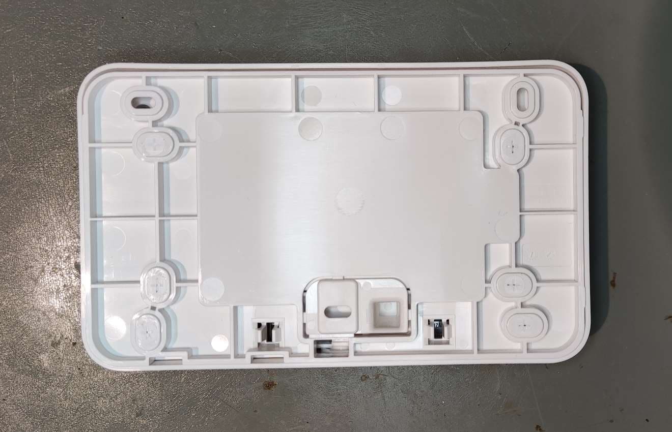
Click to zoom
Application Details
- Equipment Class
- PUB - Part 15 Unlicensed PCS Base Station
- Date of Grant
- Oct 04, 2023
- Application Purpose
- Original Equipment
- Date of Application
- Oct 04, 2023
- Equipment Note
- Central Unit in the alarm suite
- Frequency Range
- 1921.53600000 - 1928.44800000
- Company
- Verisure Sarl
- Country
- Switzerland
Documents & Files
Document Text
Text extracted from the exhibit documents filed with the FCC. Open a document above to read the original.
Users Manual
User Guide Verisure Alarms Contents Welcome to Verisure 3 Description of the alarm system 4 Arming Modes 6 Control devices: description and use 7 My Verisure App 11 Codewords 12 FCC 13 Recommendations 14 3 Welcome to Verisure Congratulations, you have just installed the Verisure Smart Alarm in your home or business; an advanced security system designed to offer you maximum protection and, at the same time, ensure easy and comfortable daily use. This manual is a tool that will help you get acquainted with the alarm system in its first uses and will serve as a consultation document in case of any questions that may arise about the handling of your alarm. If you have any other questions after reading the manual. We encourage you to install the My Verisure app on your mobile or tablet. This application will allow you to know what is happening in your home or business at all times, remotely control your alarm system and access any settings. 4 My Verisure App Control your alarm system, monitor what’s happening in your home or business, and contact Verisure via chat. Wherever you are, from your mobile or tablet. Motion Photo/Video Detectors with colour camera and night vision GWL-MD-C1 They protect the interior of your home or business. When they detect unauthorised movement, they take images that are sent to our Alarm Receiving Centre, where we check in seconds what is happening. Voicepad GWL-SVK and Smart Keys It allows you to easily connect and disconnect the alarm with the method of your choice: by presenting one of the smart keys, entering a numeric code or using the remote control. The input reader incorporates speech/listening system, siren and an SOS button for emergencies. Shock Sensor opening detector GWL-MC2-SHOCK Protects doors and windows thanks to its triple detection system sensitive to openings, shocks and vibrations, which allows us to detect the intruder even before they enter. Description of the alarm system 5 My Verisure App Control your alarm system, monitor what’s happening in your home or business, and contact Verisure via chat. Wherever you are, from your mobile or tablet. Central Unit GW-CU2L Its function is to manage signals from all alarm devices and transmit them to the Verisure Alarm Receiving Centre. To ensure signal transmission, it has Ethernet (ETH), WLAN, 4G, 3G and GSM network connection which are immune to frequency inhibitors. Remote Control GWL-KF-WR Easily control your alarm system. SOS Button GWL-SPB The SOS Button provides the user with a discrete process to notify Verisure that an Emergency is occurring, and you require immediate help. When triggered, Verisure will immediately review the situation and actively respond to the situation faced. 6 MY VERISURE APPREMOTE CONTROL Disconnected Partial Mode Perimeter Mode KEY READER WHEN YOU LEAVE YOUR HOME OR BUSINESS CONNECTION IN FULL MODE When you leave your home or business and there is no one left inside, set the alarm to away mode. With this arming mode, all detectors are active and your property is fully protected. WHEN YOU’RE AT HOME OR BUSINESS ARMING IN HOME-MODE If you are in your home or business, we recommend connecting the alarm in home mode to stay protected. This will activate only the detectors in the areas you configure, so you can move freely around the rest of the installation. Note: we recommend arming the partial mode as long as you’re inside your home or business. WHEN YOU’RE AT HOME OR BUSINESS ARMING IN PERIMETER MODE The perimeter mode allows you to activate only perimeter detectors,* so that the outer area is protected. *This feature will be available on future upgraded perimeter detectors WHEN YOU ENTER YOUR HOME OR BUSINESS DISARMING When you access your home or business, disarm the alarm. This way, you can freely access and move throughout the installation, as the detectors will be no longer active KEY READER MY VERISURE APP REMOTE CONTROL KEY READER MY VERISURE APP KEY READER REMOTE CONTROL MY VERISURE APP Away Mode Arming Modes 7 TO CHANGE THE STATUS OF YOUR ALARM Follow the steps below: Click the mode that you want to activate your system in 1 , 2 , 3 , 4 or Identify how you want to arm the system through one of the two options: 1 2 3 4 5 6 7 1 Disarm Button Arm Button in Perimeter Mode Arm Button for Home Mode Arm Button for Away Mode Keyboard and Key Reader < Cancel/Delete SOS Button (Hold down until all indicators light up) 2 3 4 5 6 7 Enter your pin code Present your smart key by placing it in the cen- tre of the keypad ( 5 ). Option 1Option 2 Control devices: description and use Voicepad Speaker and siren LED’s Microphone 8 4 7 11 Voicepad: Understanding the LED notifications The Voicepad will notify you of any technical information you will need to keep your system working optimally. When you have a notification you will see two Amber lights. To listen to the notification, tap the microphone and then identify yourself by presenting your smart key or entering your pin code. Finally, press the “cancel/delete” button (<) and the indicator lights will turn off. The indicator lights will remain illuminated in yellow - until it is resolved. Note: You can press the “cancel/ delete” button (<) at any time to stop listening to notifications The Voicepad will also notify you of any security information you have received while your system has been armed. When you have a security notification you will see four amber LEDs. The numbers associated with the device(s) that have been affected will be displayed on the keyboard. Finally, to confirm that you have been informed you must press the “cancel/ delete” button (<). Technical NotificationsIntrusion notifications Control devices: description and use 9 1 Control devices: description and use Input reader: signalled by illuminated indicators If when connecting your alarm it illuminates with four LEDs light up in the middle as red and yellow, it means that you must listen to the notifications before connecting the system. After listening to…
Text truncated - open the document above for the full version.
Attestation Statements
Hualing Dong, President
External Photos
EXTERNAL PHOTOGRAPHS ABSTRACT External photos of the Equipment Under Test (GW-CU2L). This document contains 13 photographs PHOTO 1 PHOTO 2 PHOTO 3 PHOTO 4 PHOTO 5 PHOTO 6 PHOTO 7 PHOTO 8 PHOTO 9 PHOTO 10 PHOTO 11 PHOTO 12 PHOTO 13
ID Label/Location Info
CU2L PRODUCT LABEL CONFIDENTIAL ABSTRACT This document describes the Central Unit 2 Lat Am (CU2L) label in terms of layout and content. CONFIDENTIAL CU2L Product Label Specification Page 2 of 6 TABLE OF CONTENTS 1 Label specification ........................................................................................................................ 3 1.1 Label description ................................................................................................................... 3 2 Visual Example ........................................................................................................................ 4 3 Notes ....................................................................................................................................... 5 3.1 Visual Appearance ................................................................................................................ 5 3.2 Printed Example .................................................................................................................... 6 CONFIDENTIAL CU2L Product Label Specification Page 3 of 6 1 LABEL SPECIFICATION 1.1 LABEL DESCRIPTION • Description: CU2L Product Label • Article number: 009435_A • (Brady catalog nr:) Y-4273132 • Size (WxH): 47x34 mm, see drawing below • Material description: White Polyester, Glossy White • Body material: Brady B423 • Ribbon: Brady R-6000HF • Print resolution: 600dpi CONFIDENTIAL CU2L Product Label Specification Page 4 of 6 2 VISUAL EXAMPLE Font size and dimensions are suggestions. CONFIDENTIAL CU2L Product Label Specification Page 5 of 6 3 NOTES 3.1 VISUAL APPEARANCE CONFIDENTIAL CU2L Product Label Specification Page 6 of 6 3.2 PRINTED EXAMPLE
Internal Photos
INTERNAL PHOTOGRAPHS ABSTRACT Internal photos of the Equipment Under Test (GW-CU2L). This document contains 9 photographs PHOTO 1 PHOTO 2 PHOTO 3 PHOTO 4 PHOTO 5 PHOTO 6 PHOTO 7 PHOTO 8 PHOTO 9
RF Exposure Info
DEKRA Testing and Certification, S.A.U. Parque Tecnológico de Andalucía, c/ Severo Ochoa nº 2 · 29590 Campanillas · Málaga · España C.I.F. A29 507 456 Report No: (NIE) 72872RAN.007A1 2023-09-27 Test report No: NIE: 72872RAN.007A1 Assessment report RF EXPOSURE REPORT ACCORDING TO FCC 47 CFR Part 2.1091; FCC 47 CFR Part 1.1307 FCC 47 CFR Part 1.1310 (*) Identification of item under evaluation Central Unit 2 - LatAm variant (*) Trademark Verisure (*) Model and /or type reference GW-CU2L (*) Other identification of the product FCC ID: 2A93W-GW-CU2L IC: Not provided HW version: A5 SW version: 1.8.26 (*) Features Central processing, Ethernet, Wi-Fi, Cellular, DECT, ISM (*) Manufacturer Verisure Sàrl Chemin Jean-Baptiste Vandelle 3 1290 Versoix (Switzerland) Test method requested, standard FCC 47 CFR Part 2.1091 Radiofrequency radiation exposure evaluation: mobile devices. FCC 47 CFR Part 1.1307: Actions that may have a significant environmental effect, for which Environmental Assessments (EAs) must be prepared. FCC 47 CFR Part 1.1310: Radiofrequency radiation exposure limits. Summary IN COMPLIANCE Approved by (name / position & signature) Miguel Lacave Antennas Lab Manager Date of issue 2023-09-27 Report template No FAN36_02 (*) “Data provided by the client” DEKRA Testing and Certification, S.A.U. Parque Tecnológico de Andalucía, c/ Severo Ochoa nº 2 · 29590 Campanillas · Málaga · España C.I.F. A29 507 456 Report No: (NIE) 72872RAN.007A1 Page 2 of 10 2023-09-27 Index Competences and guarantees .................................................................................................... 3 General conditions ...................................................................................................................... 3 Data provided by the client .......................................................................................................... 3 Identification of the client............................................................................................................. 3 Document history ........................................................................................................................ 3 Appendix A: FCC RF Exposure assessment result ..................................................................... 4 General description of the device under evaluation ................................................................ 5 Evaluation Results .................................................................................................................. 7 Appendix B: FCC RF Exposure information ................................................................................ 8 RF Exposure determination of exemption ............................................................................... 9 DEKRA Testing and Certification, S.A.U. Parque Tecnológico de Andalucía, c/ Severo Ochoa nº 2 · 29590 Campanillas · Málaga · España C.I.F. A29 507 456 Report No: (NIE) 72872RAN.007A1 Page 3 of 10 2023-09-27 Competences and guarantees In order to assure the traceability to other national and international laboratories, DEKRA Testing and Certification, S.A.U. has a calibration and maintenance program for its measurement equipment. DEKRA Testing and Certification, S.A.U. guarantees the reliability of the data presented in this report, which is the result of the measurements and the tests performed to the item under test on the date and under the conditions stated on the report and, it is based on the knowledge and technical facilities available at DEKRA Testing and Certification, S.A.U. at the time of performance of the test. DEKRA Testing and Certification, S.A.U. is liable to the client for the maintenance of the confidentiality of all information related to the item under test and the results of the test. The results presented in this Assessment Report apply only to the particular item under test established in this document. IMPORTANT: No parts of this report may be reproduced or quoted out of context, in any form or by any means, except in full, without the previous written permission of DEKRA Testing and Certification, S.A.U. General conditions 1. This report is only referred to the item that has undergone the assessment. 2. This report does not constitute or imply on its own an approval of the product by the Certification Bodies or competent Authorities. 3. This document is only valid if complete; no partial reproduction can be made without previous written permission of DEKRA Testing and Certification, S.A.U. 4. This test report cannot be used partially or in full for publicity and/or promotional purposes without previous written permission of DEKRA Testing and Certification, S.A.U. and the Accreditation Bodies Data provided by the client The following data has been provided by the client: 1. Information relating to the description of the sample ("Identification of the item under evaluation", "Trademark", "Model and/or type reference", “General description of the device”, “Other identification of the product”). 2. Maximum output power, maximum antenna gain and use distance information. 3. The device under evaluation consists of a Central Unit 2 - LatAm variant. Central Unit of the alarm suite. It acts as the main hub and gateway. DEKRA Testing and Certification S.A.U. declines any responsibility with respect to the information provided by the client and that may affect the validity of results. Identification of the client Verisure Sàrl Chemin Jean-Baptiste Vandelle 3 1290 Versoix (Switzerland) Document history Report number Date Description 72872RAN.007 2023-09-07 First release 72872RAN.007A1 2023-09-27 Second release. Applicable UMTS V and LTE Band 5 exposure limits updated from §1.1307(b)(3).i.(C) to §1.1307(b)(3).i.(B) limit. This modification test report cancels and replaces the test report 72872RAN.007. DEKRA Testing and Certification, S.A.U. Parque Tecnológico de Andalucía, c/ Severo Ochoa nº 2 · 29590 Campanillas · Málaga · España C.I.F. A29…
Text truncated - open the document above for the full version.
Test Report
GW-CU2L ANTENNAS DATASHEET PUBLIC DOCUMENT REV. 1 – 2023-01-31 ABSTRACT Datasheet for the antennas used in the GW-CU2L product. ANTENNA MODEL NUMBERS All the antennas are part of the PCB copper pattern. Manufacturer: Verisure Antenna Model number Cellular main antenna CU2-ANT-CELL-MAIN Cellular diversity antenna CU2-ANT-CELL-DRX DECT1 and ISM1 antenna CU2-ANT-DECT-ISM-1 DECT2 and ISM2 antenna CU2-ANT-DECT-ISM-2 ISM3 antenna CU2-ANT-ISM-3 Wi-Fi chain 0 antenna CU2-ANT-WIFI-A Wi-Fi chain 1 antenna CU2-ANT-WIFI-B DESCRIPTION OF THE ANTENNAS CELLULAR ANTENNAS Both the primary (main) antenna and the diversity antenna are of monopole type, i.e., they have a feed connection but not a ground connection. The primary antenna also has a parasitic element that only has a ground connection. Please note that the cellular diversity antenna is for reception only. ISM AND DECT ANTENNAS GW-CU2L has three ISM-antennas and two of those antennas also include a DECT-1900MHz branch. All three antennas are of IFA/PIFA type, i.e., they have one feed connection each and one ground connection each. WI-FI ANTENNAS Both the WiFi-antenna A (chain 0) and the WiFi-antenna B (chain 1) are of monopole type, i.e., they have a feed connection but not a ground connection. FREQUENCY RANGE, EFFICIENCY & GAIN The following tables include relevant efficiency and gain data can for the antennas in this product. Cellular main antenna Frequency band [MHz] Frequency [MHz] Efficiency [dB] Directivity [dBi] Gain [dBi] 699 - 960 960 -4.8 3.9 -0.9 1710 - 2690 2500 -3.2 5.4 2.2 Figures at maximum gain over the frequency band Cellular diversity antenna Frequency band [MHz] Frequency [MHz] Efficiency [dB] Directivity [dBi] Gain [dBi] 699 - 960 925 -4.0 4.7 0.7 1710 - 2690 2600 -4.7 6.1 1.4 Figures at maximum gain over the frequency band DECT1 and ISM1 antenna Frequency band [MHz] Frequency [MHz] Efficiency [dB] Directivity [dBi] Gain [dBi] ISM 916 - 926 916 -4.3 2.7 -1.6 DECT 1905 - 1930 1930 -3.5 3.6 0.1 Figures at maximum gain over the frequency band DECT2 and ISM2 antenna Frequency band [MHz] Frequency [MHz] Efficiency [dB] Directivity [dBi] Gain [dBi] ISM 916 - 926 916 -4.2 4.5 0.3 DECT 1905 - 1930 1930 -3.6 5.1 1.5 Figures at maximum gain over the frequency band ISM3 antenna Frequency band [MHz] Frequency [MHz] Efficiency [dB] Directivity [dBi] Gain [dBi] ISM 916 - 926 926 -5.4 2.7 -2.7 Figures at maximum gain over the frequency band Wi-Fi chain 0 antenna Frequency band [MHz] Frequency [MHz] Efficiency [dB] Directivity [dBi] Gain [dBi] 2.4 GHz band 2401 - 2484 2412 -2.5 N/A 1.3 5 GHz band 5180 - 5825 5500 -1.9 N/A 3.1 Figures at maximum gain over the frequency band Wi-Fi chain 1 antenna Frequency band [MHz] Frequency [MHz] Efficiency [dB] Directivity [dBi] Gain [dBi] 2.4 GHz band 2401 - 2484 2401 -4.6 N/A 2.2 5 GHz band 5180 - 5825 5700 -1.9 N/A 5.0 Figures at maximum gain over the frequency band RADIATION PATTERNS, 3D-CUTS & 2D-CUTS CELLULAR MAIN ANTENNA At 960 MHz Elevation, azimuth 0deg Elevation, azimuth 90deg Azimuth At 2500 MHz Elevation, azimuth 0deg Elevation, azimuth 90deg Azimuth CELLULAR DIVERSITY At 925 MHz Elevation, azimuth 0deg Elevation, azimuth 90deg Azimuth At 2600 MHz Elevation, azimuth 0deg Elevation, azimuth 90deg Azimuth DECT1 AND ISM1 ANTENNA At 916 MHz (ISM) Elevation, azimuth 0deg Elevation, azimuth 90deg Azimuth At 1930MHz (DECT) Elevation, azimuth 0deg Elevation, azimuth 90deg Azimuth DECT2 AND ISM2 ANTENNA At 916 MHz (ISM) Elevation, azimuth 0deg Elevation, azimuth 90deg Azimuth At 1930 MHz (DECT) Elevation, azimuth 0deg Elevation, azimuth 90deg Azimuth ISM3 ANTENNA At 926 MHz (ISM) Elevation, azimuth 0deg Elevation, azimuth 90deg Azimuth WI-FI CHAIN 0 ANTENNA At 2412 MHz Elevation, azimuth 0deg Elevation, azimuth 90deg Azimuth At 5500 MHz Elevation, azimuth 0deg Elevation, azimuth 90deg Azimuth WI-FI CHAIN 1 ANTENNA At 2401 MHz Elevation, azimuth 0deg Elevation, azimuth 90deg Azimuth At 5700 MHz Elevation, azimuth 0deg Elevation, azimuth 90deg Azimuth
Test Report
2023-07-11 Page 1 of 61 TEST REPORT Test Report No.: 1-4862/22-01-03 Testing Laboratory Applicant cetecom advanced GmbH Untertürkheimer Straße 6 – 10 66117 Saarbrücken/Germany Phone: + 49 681 5 98 - 0 Fax: + 49 681 5 98 - 9075 Internet: http://www.cetecomadvanced.com e-mail: [email protected] Accredited Test Laboratory: The testing laboratory (FCC part 15 D) is accredited according to DIN EN ISO/IEC 17025 (2005) by the Deutsche Akkreditierungsstelle GmbH (DAkkS) The accreditation is valid for the scope of testing procedures as stated in the accreditation certificate with the registration number: D-PL-12076-01-04 / -05 Verisure Sàrl Chemin Jean-Baptiste Vandelle 3 1290, Versoix Switzerland Contact: Andrew Wells e-mail: [email protected] Phone: +41 797856160 Manufacturer Verisure Sàrl Chemin Jean-Baptiste Vandelle 3 1290, Versoix Switzerland Test Standard/s FCC Part 15, subpart D: 2016 Isochronous UPCS Device 1920 – 1930 MHz Industry Canada RSS-213, Issue 3: 2015 2 GHz Licence-exempt Personal Communication Service Devices (LE-PCS) Test Item Kind of product: Central Unit 2 – LatAm variant Product name: GW-CU2L HVIN: PMN: FVIN: HMN: FCC ID: / / / / 2A93W-GW-CU2L IC: / S/N serial number: Radiated: 26MNK2HH Conducted: 26MNJZ2L, 26MNJZAM, 26MNJY2Q HW hardware status: A5 SW software status: 1.8.26 Frequency [MHz]: 1920 -1930 Type of Modulation: Digital (Gaussian Frequency Shift Keying) Number of channels: 5 RF Channels, 5x12 = 60 TDMA Duplex Channels Antenna: 2 internal antennas Power Supply: AC/DC power supply, 100 – 240 Vac Temperature Range: -20°C to 50°C Test Report authorised: Test performed: 2023-07-11 Luckenbill, Andreas 2023-07-11 Wolf, Joachim Head of Radio and SAR Services Head of New Services Test report no.: 1-4862/22-01-03 2023-07-11 Page 2 of 61 1 Table of contents 1 Table of contents ......................................................................................................................................... 2 2 General information .................................................................................................................................... 4 2.1 Notes and disclaimer ....................................................................................................................... 4 2.2 Application details ........................................................................................................................... 4 3 Test standard/s: ........................................................................................................................................... 4 4 Test Environment ........................................................................................................................................ 5 5 Reporting statements of conformity – decision rule ............................................................................... 5 6 Measurement uncertainty ........................................................................................................................... 6 7 Summary of Measurement Results ........................................................................................................... 7 8 Test Set-up ................................................................................................................................................... 8 8.1 Frequency Measurements ............................................................................................................... 8 8.2 Timing Measurements ..................................................................................................................... 8 8.3 Conducted Emission Test ............................................................................................................... 8 8.4 Radiated Emission Test ................................................................................................................... 9 8.5 Power Line Conducted Emissions Test ....................................................................................... 11 8.6 Monitoring Tests............................................................................................................................. 12 8.7 Radiated Output Power Test ......................................................................................................... 12 9 Detailed Test Results ................................................................................................................................ 13 9.1 Power Line Conducted Emissions ............................................................................................... 13 9.2 Digital Modulation Techniques ..................................................................................................... 16 9.3 Labeling Requirements .................................................................................................................. 16 9.4 Antenna Requirements .................................................................................................................. 17 9.5 Channel Frequencies ..................................................................................................................... 17 9.6 Automatic Discontinuation of Transmission ............................................................................... 18 9.7 Peak Power Output ........................................................................................................................ 19 9.8 Emission Bandwidth B ........................................................................................................... 22 9.9 Power Spectral Density ................................................................................................................. 25 9.10 In-Band Unwanted Emissions, Conducted .............................................................................. 28 9.11 Out-of-Band Emissions, Radiated.......................................................................................…
Text truncated - open the document above for the full version.
Test Setup Photos
DEKRA Testing and Certification, S.A.U. Parque Tecnológico de Andalucía, c/ Severo Ochoa nº 2 · 29590 Campanillas · Málaga · España C.I.F. A29507456 Report No: 72872RRF.003 2023-08-11 Appendix B: Photographs DEKRA Testing and Certification, S.A.U. Parque Tecnológico de Andalucía, c/ Severo Ochoa nº 2 · 29590 Campanillas · Málaga · España C.I.F. A29507456 Report No: 72872RRF.003 Page 2 of 4 2023-08-11 EQUIPMENT VIEW FOR RADIATED TESTS DEKRA Testing and Certification, S.A.U. Parque Tecnológico de Andalucía, c/ Severo Ochoa nº 2 · 29590 Campanillas · Málaga · España C.I.F. A29507456 Report No: 72872RRF.003 Page 3 of 4 2023-08-11 TEST SETUP FOR RADIATED MEASUREMENTS BELOW 1GHz 1 DEKRA Testing and Certification, S.A.U. Parque Tecnológico de Andalucía, c/ Severo Ochoa nº 2 · 29590 Campanillas · Málaga · España C.I.F. A29507456 Report No: 72872RRF.003 Page 4 of 4 2023-08-11 TEST SETUP FOR RADIATED MEASUREMENTS BETWEEN 1GHz TO 17 GHz
Test Setup Photos
2023-09-25 Page 1 of 4 Annex A: Photographs of the Test Set- up Photo 1: Radiated Emission Photo 2: Radiated Emission Test report no.: 1-4862/22-01-03 2023-09-25 Page 2 of 4 Annex B: External Photographs of the EUT Photo 1: Photo 2: Test report no.: 1-4862/22-01-03 2023-09-25 Page 3 of 4 Annex C: Internal Photographs of the EUT Photo 1: Photo 2: Test report no.: 1-4862/22-01-03 2023-09-25 Page 4 of 4 Photo 3:
Contact Information
Applicant
Andrew Wells(Chief Products and Services Officer)
Test Firm
cetecom advanced GmbHGerald Schmidt
Technical Specifications
| # | Rule Parts | Frequency Range | Power Output |
|---|---|---|---|
| 1 | 15D | 1.92 GHz - 1.93 GHz | 89.10 mW |
Other Applications from Verisure Sarl
2A93W-GWL-KP-MOK1
May 05, 2026Outdoors device which main purpose is arm and disarm the alarm system.It is a fixed device, composed by five (5) buttons and it also implements NFC technology. Can also be used as a keypad allowing the use of a code.
Equipment Class
DTS - Digital Transmission System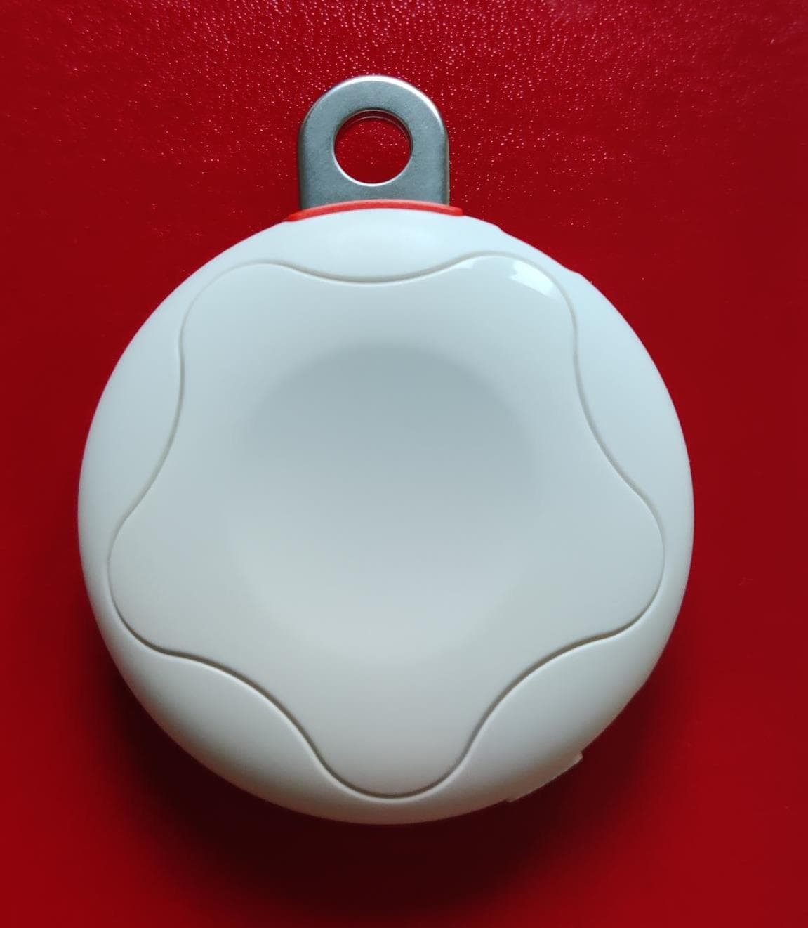
2A93W-GWL-KF-WR
Jul 16, 2023Keyfob
Equipment Class
JAB - Part 15 Class B Digital Device
2A93W-GWL-MC2-SHOCK
Jul 05, 2023Shock sensor MC2.1
Equipment Class
JAB - Part 15 Class B Digital Device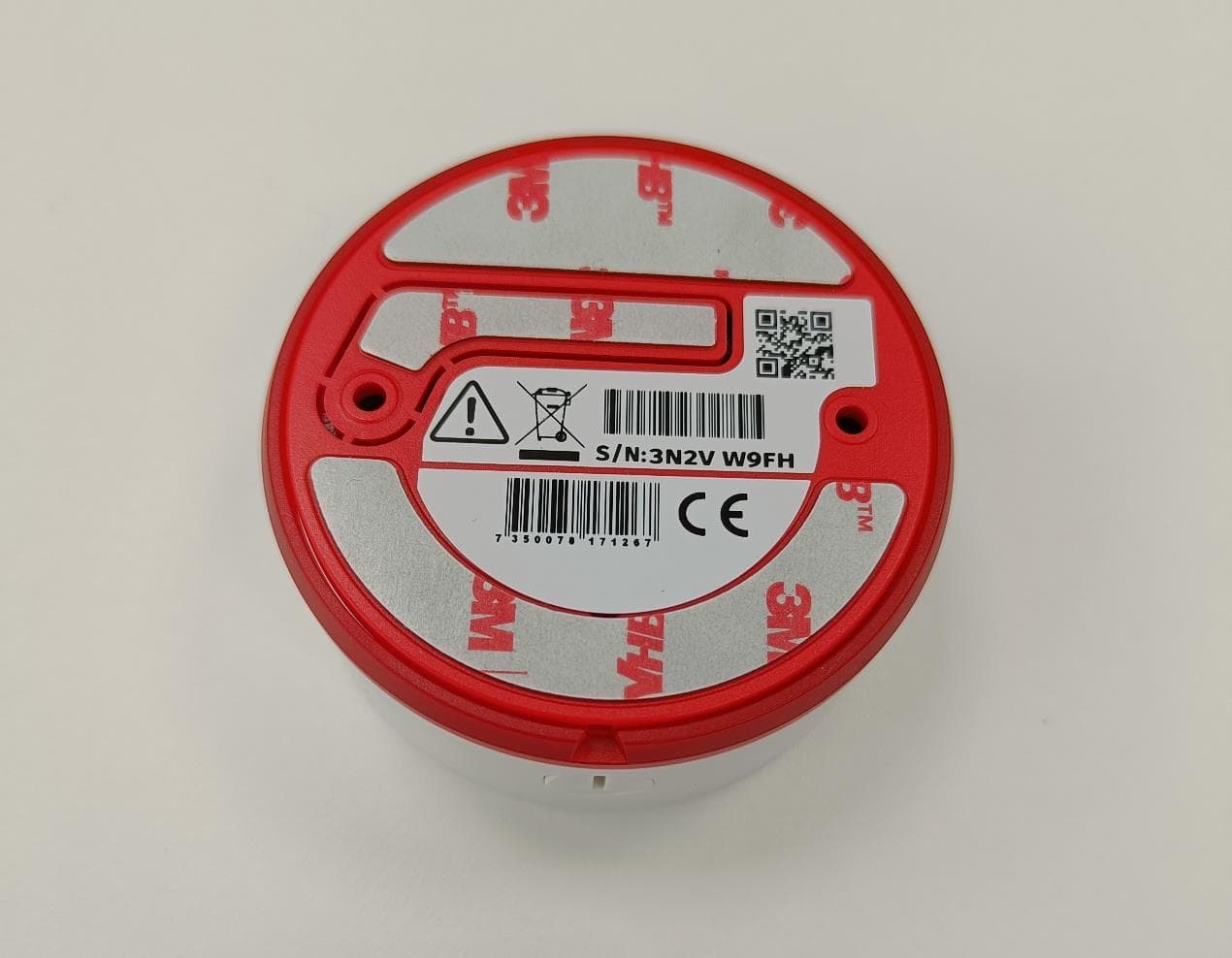
2A93W-GWL-SPB
Jul 05, 2023Smart Panic Button
Equipment Class
JAB - Part 15 Class B Digital Device