2A96E-KIM1-HW1-5IoT transmitter module for satellite ground stations
KINEIS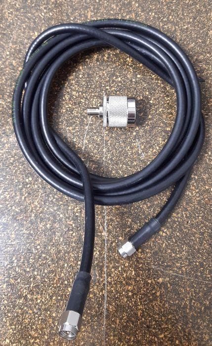
Click to zoom
Application Details
- Equipment Class
- TNB - Licensed Non-Broadcast Station Transmitter
- Date of Grant
- Jun 27, 2023
- Application Purpose
- Original Equipment
- Date of Application
- Jun 25, 2023
- Equipment Note
- IoT transmitter module for satellite ground stations
- Frequency Range
- 399.91000000 - 402.99000000
- Company
- KINEIS
- Country
- France
Documents & Files
Document Text
Text extracted from the exhibit documents filed with the FCC. Open a document above to read the original.
Users Manual
Kinéis SAS au capital de 15 687 654 euros 11, rue Hermès, Parc Technologique du Canal, 31 520 Ramonville Saint-Agne France RCS Toulouse - SIREN 841 489 123 Reference: Issue: Date: KINEIS-NT-19-0018 2.4 14/06/2023 KIM1 Integration manual KIM1 - Integration manual v2.4 1 No part of this document may be reproduced in any form, neither communicated nor used without the prior agreement of Kinéis. TABLE OF CONTENTS 1. Introduction 3 Versioning 4 Revision history 6 Related documents 7 2. Typical application circuit 8 Boosted 3.3V integration 9 3. UART Communication 10 AT commands syntax 10 Timing constraints 11 AT commands description 11 1. Information type commands 11 a. ID number 11 b. Firmware version 11 c. Serial number 12 d. Transmission frequency 12 2. Parameter type commands 13 a. Transmission power 13 b. Message format 14 3. Action type commands 15 a. Save configuration 15 b. Ping 15 c. Message transmission 16 d. CW 17 Error responses 17 4. Transmission protocol 19 KIM1 - Integration manual v2.4 2 No part of this document may be reproduced in any form, neither communicated nor used without the prior agreement of Kinéis. Frame format 19 Message format 20 1. Raw format (default) 20 2. Kinéis standard format 21 Transmission strategy 22 1. Positioning/continuous tracking 22 2. “Keep alive” 23 3. Simple data collection 23 4. Alerting 24 5. Transmission on satellite passes 24 5. Antenna associated with 25 Module interface board 25 Coil antenna 25 Whip antenna 27 RF exposure 27 6. Additional information 28 Contact & support 28 Legal Notices 28 Certification 28 Statements 29 Frequency Use 30 KIM1 - Integration manual v2.4 3 No part of this document may be reproduced in any form, neither communicated nor used without the prior agreement of Kinéis. 1. Introduction Kinéis products makes satellite connectivity easy to access and it is our goal to make integration and industrialization process as streamlined as possible. The KIM1 module developed by Kinéis is a low-power transmitter module based on Argos-2 standard and fully certified by Kinéis and CNES (French Space Agency). It enables communication with all the Kinéis/Argos polar LEO satellites and provides global connectivity to IoT devices for data collection and positioning. The use of Argos RF signals and protocols ensures very low power consumption for device within line of sight of Kinéis/Argos satellites. The module is specifically designed for ease of use, to shorten development time and thus decrease time to market. It offers IoT device manufacturers the possibility to integrate their end devices quickly and easily into the Kinéis network and is available for industrialization of satellite connected device in large volumes. This document is an integration manual for the KIM1 transmitter module by Kinéis, complementing the component datasheet (see §1.3 Related documents for reference). This manual will bring you information regarding: • Typical integration circuit • UART interface • Transmission protocol, including message formatting and transmission strategies Warning: Please refer to the paragraph below, 1.1 Versioning, to make sure you are reading the documentation suited to your module version. For further assistance, feel free to contact Kinéis at the following link: https://www.kineis.com/contact/ KIM1 - Integration manual v2.4 4 No part of this document may be reproduced in any form, neither communicated nor used without the prior agreement of Kinéis. Versioning Please refer to the table below to identify the version of the documentation (Datasheet and Integration Manual) related to your module series, considering the following information: • The hardware (HW) version, determined by the Serial Number • The firmware (FW) or software (SW) version, determined with the AT command AT+FW=? Warning: most of the time, the Serial Number can be an indication for the FW version looking at the correspondence table below. However, the FW version must be finally determined with the AT command AT+FW=? since the KIM1 may have been reprogrammed with a newer FW version after manufacturing. Label Serial number Manufacturing FW version Datasheet reference and version Integration Manual reference and version 0719-xxxx 1219-xxxx 0120-xxxx 0220-xxxx KIM_HW1.1_ • SW0.2 • SW1.0 KIM_HW1.3_ • SW1.0 • SW1.1 • SW1.2 KINEIS-SP-20-0147 KIM1 Datasheet v1.0.pdf KINEIS-NT-19-0018 KIM1 Integration Manual v2.0.pdf KIM132008xxxxx KIM_HW1.3_SW1.3 KINEIS-SP-20-0147 KIM1 Datasheet v1.2.pdf KINEIS-NT-19-0018 KIM1 Integration Manual v2.0.pdf KIM132103xxxxx KIM1_V1.4 KINEIS-SP-20-0147 KIM1 Datasheet v1.2.pdf KINEIS-NT-19-0018 KIM1 Integration Manual v2.1.pdf KIM132109xxxxx KIM1_V2.0 KINEIS-SP-20-0147 KIM1 Datasheet v2.0.pdf KINEIS-NT-19-0018 KIM1 Integration Manual v2.2.pdf KIM132111xxxxx KIM132112xxxxx KIM132201xxxxx KIM1_V2.1 KINEIS-NT-19-0018 KIM1 Integration Manual v2.3.pdf KIM1523XXXXXXX FW3.x.x KINEIS-SP-20-0147 KIM1 Datasheet v2.1.pdf KINEIS-NT-19-0018 KIM1 Integration Manual v2.4.pdf KIM1 - Integration manual v2.4 5 No part of this document may be reproduced in any form, neither communicated nor used without the prior agreement of Kinéis. All further modules will be produced and distributed with the latest hardware and software versions. In case of any doubt regarding your module version and corresponding documentation, do not hesitate to contact us. KIM1 - Integration manual v2.4 6 No part of this document may be reproduced in any form, neither communicated nor used without the prior agreement of Kinéis. Revision history Issue Date Ref Modifications 1.0 to 1.6 Apr 23, 2019 to Jul 26, 2019 JI, AJ, SV Document creation and updates 2.0 Jun 12, 2020 CT Suppression of the following paragraphs (transferred into KIM1 Datasheet): 1. Product description 2. Device information 3. Electrical characteristics Update of the following paragraphs: 2. Typical application circuit 3. UART communication 4. Transmission protocol 2.1 Feb 8, 2022 CT, VG • Modification of §2 Typical applica…
Text truncated - open the document above for the full version.
Users Manual
Kinéis SAS au capital de 15 687 654 euros 11, rue Hermès, Parc Technologique du Canal, 31 520 Ramonville Saint-Agne France RCS Toulouse - SIREN 841 489 123 Reference: Issue: Date: KINEIS-SP-20-0147 2.1 14/06/2023 KIM1 Datasheet KIM1 – Datasheet v2.1 1 No part of this document may be reproduced in any form, neither communicated nor used without the prior agreement of Kinéis. TABLE OF CONTENTS 1. Introduction 4 1.1. Versioning 5 1.2. Revision history 7 1.3. Related documents 7 2. Product description 8 2.1. Overview 8 2.2. Main features 8 2.3. Functional description 9 2.4. Commands / controls 10 2.5. State transition diagram 10 3. Electrical specifications 11 3.1. Absolute Maximum Ratings 11 3.2. Nominal Operation Ratings 12 3.2.1. Electrical 12 3.2.2. Radio frequency 12 3.2.3. Logic 13 3.2.3.1. Digital inputs 13 3.2.3.2. Digital outputs 13 3.3. Current consumption 14 3.3.1. Consumption profile overview 14 3.3.2. Transmission mode 15 3.3.2.1. TCXO warmup 16 3.3.2.2. VPA_ON, Tx status 16 3.3.2.3. Transmission 17 3.3.2.4. Variation of temperature 18 3.3.2.5. Overall consumption for typical transmission cycle 18 KIM1 – Datasheet v2.1 2 No part of this document may be reproduced in any form, neither communicated nor used without the prior agreement of Kinéis. 4. Module pin-out 19 4.1. Pad assignments 19 4.2. Pin descriptions 20 5. Mechanical specifications 22 5.1. Module dimensions 22 5.2. Pin intervals 23 5.3. PCB Footprint 24 6. Storage and soldering 25 6.1. Storage information 25 6.1.1. Storage and handling 25 6.1.2. Moisture sensitivity 25 6.2. Soldering process 26 7. Ordering and Marking 27 7.1. Ordering 27 7.2. Marking 28 8. Additional information 29 8.1. Contact and support 29 8.2. Known-issues 29 8.2.1. Power supply instabilities 29 8.2.2. Impedance issue 29 8.3. Specific terms of use 29 8.4. Frequency Use 31 8.5. Certifications 31 8.6. Legal notices 32 8.7. Statements 32 Appendix A – EU type Examination Certificate 34 KIM1 – Datasheet v2.1 3 No part of this document may be reproduced in any form, neither communicated nor used without the prior agreement of Kinéis. List of figures Figure 1: KIM1 functional diagram ........................................................................................................... 9 Figure 2: KIM1 state digram ................................................................................................................... 10 Figure 3: Typical consumption profile overview .................................................................................... 15 Figure 4: Typical current consumption profile for TCXO warmup........................................................... 16 Figure 5: Typical current consumption profile for VPA_ON and Tx status .............................................. 16 Figure 6: Current consumption profile for transmission at different power values ................................ 17 Figure 7: Consumption profile for transmission at limit temperature value ........................................... 18 Figure 8: KIM1 pad assignments ............................................................................................................ 19 Figure 9: KIM1 mechanical dimensions ................................................................................................. 22 Figure 10: Pin pitches and placements ................................................................................................. 23 Figure 11: PCB footprint ........................................................................................................................ 24 Figure 12: Temperature profile for soldering ........................................................................................ 26 Figure 13: Individual antistatic bags and 50 units plastic trays ............................................................... 27 Figure 14: KIM1 marking ........................................................................................................................ 28 KIM1 – Datasheet v2.1 4 No part of this document may be reproduced in any form, neither communicated nor used without the prior agreement of Kinéis. 1. Introduction Kinéis products makes satellite connectivity easy to access and it is our goal to make integration and industrialization process as streamlined as possible. The KIM1 module developed by Kinéis is a low-power transmitter module based on Argos-2 standard and fully certified by Kinéis and CNES (French Space Agency). It enables communication with all the Kinéis/Argos polar LEO satellites and provides global connectivity to IoT devices for data collection and positioning. The use of Argos RF signals and protocols ensures very low power consumption for device within line of sight of Kinéis/Argos satellites. The module is specifically designed for ease of use, to shorten development time and thus decrease time to market. It offers IoT device manufacturers the possibility to integrate their end devices quickly and easily into the Kinéis network and is available for industrialization of satellite connected device in large volumes. This document is the datasheet for the KIM1 transmitter module by Kinéis, which is complemented by the integration (see §Erreur ! Source du renvoi introuvable. Erreur ! Source du renvoi introuvable. for reference). Warning: Please refer to the paragraph below, 1.1 Versioning, to make sure you are reading the documentation suited to your module version. For further assistance, feel free to contact Kinéis at the following link: https://www.kineis.com/contact/ KIM1 – Datasheet v2.1 5 No part of this document may be reproduced in any form, neither communicated nor used without the prior agreement of Kinéis. 1.1. Versioning Please refer to the table below to identify the version of the documentation (Datasheet and Integration Manual) related to your module series, considering the following information: • The hardware (HW) version, determined by the Serial Number • The firmware …
Text truncated - open the document above for the full version.
Attestation Statements
Kinéis SAS au capital de 15 687 654 euros 11, rue Hermès, Parc Technologique du canal, 31 520 Ramonville-Saint-Agne France RCS Toulouse – SIREN 841 489 123 To: Federal Communications Commission Authorization and Evaluation Division 7435 Oakland Mills Road Columbia, MD 21046 USA Kinéis, Ramonville-Saint-Agne (France) June 14 th , 2023 Object: Attestation Statements Part 2.911(d)(7) Filing FCC ID: 2A96E-KIM1-HW1-5 Kinéis (“the applicant”) certifies that, as of the date of the filing of the application Kinéis Inc. C/O Woods Hole Group is our designated U.S. agent for service of process for the above referenced FCC ID. Kinéis accepts to maintain an agent for no less than one year after the grantee has terminated all marketing and importation or the conclusion of any Commission-related proceeding involving the equipment. Kinéis Inc. C/O Woods Hole Group accepts, as of the date of the filing of the application, the obligation of the designated U.S. agent for service of process for the above referenced FCC ID. Designated U.S. Agent Information: Name: Kinéis Inc. C/O Woods Hole Group Address: 4390 Parliament Place Suite Q MD 20706 Lanham Contact Person : Alexandre TISSERANT Email : [email protected] Sincerely, U.S. agent company name Kinéis Inc. C/O Woods Hole Group U.S. agent Contact person Alexandre TISSERANT U.S. agent signature
Attestation Statements
Kinéis SAS au capital de 15 687 654 euros 11, rue Hermès, Parc Technologique du canal, 31 520 Ramonville-Saint-Agne France RCS Toulouse – SIREN 841 489 123 Date: 03-23-2023 To: Federal Communications Commission Authorization and Evaluation Division 7435 Oakland Mills Road Columbia, MD 21046 USA Ref: Attestation Statements Part 2.911(d)(5)(i) and Part 2.911(d)(5)(ii) Filing Re. KDB 986446 D01 FCC ID: 2A96E-KIM1-HW1-5 Dear Sir or Madam, Kinéis (“the applicant”) certifies that the equipment for which authorization is sought is not “covered” equipment prohibited from receiving an equipment authorization pursuant to section 2.903 of the FCC rules. We also certify that, as of the date of the filing of the application, the applicant is not identified on the Covered List as an entity producing “covered” equipment. If you have any questions, please contact us. Sincerely, Contact name: Vincent GAMONAL Company name: KINEIS Address: 11 rue Hermès, Ramonville-Saint-Agne 31520, France E-mail: [email protected] Tel: +33(0)5 61 39 50 87
Attestation Statements
Federal Communications Commission FCC 21-118 Before the Federal Communications Commission Washington, D.C. 20554 In the Matter of Kinéis Petition for Declaratory Ruling to Access the U.S. Market Using a Low-Earth Orbit Satellite System ) ) ) ) ) ) ) IBFS File No. SAT-PDR-20191011-00113 Call Sign S3054 ORDER AND DECLARATORY RULING Adopted: November 18, 2021 Released: November 19, 2021 By the Commission: I. INTRODUCTION 1. In this Order and Declaratory Ruling, we grant the petition (and associated waiver request) of Kinéis to access the U.S. market using frequencies of the non-voice, non-geostationary (NVNG) mobile- satellite service (MSS) and earth exploration-satellite service (EESS) through a constellation of up to 25 small, low-Earth orbit (LEO) satellites authorized by France. 1 We grant Kinéis market access in the 399.9-400.05 MHz and 401-403 MHz (Earth-to-space, i.e., uplink) bands, and the 400.15-401 MHz (space-to-Earth, i.e., downlink) band, subject to the conditions and other requirements specified herein. 2 The constellation will provide connectivity for Internet of Things (IoT) devices used by consumers in the United States and worldwide, as well as enhancements to maritime domain awareness through monitoring of maritime communications. 3 Five of the satellites will actively monitor certain signals in the 156.7625- 162.0375 MHz band transmitted by stations in the maritime service. Grant of this petition furthers the Commission’s mandate to “make available, so far as possible, to all the people of the United States ... rapid, efficient, Nation-wide, and world-wide communication services.” 4 II. BACKGROUND 2. Processing Round. For licensing and grants of U.S. market access for non-geostationary satellite orbit (NGSO)-like systems, the Commission employs a processing round procedure which 1 The Commission established a rebuttable presumption in favor of entry by satellites licensed by other World Trade Organization (WTO) member countries to provide services covered by the U.S. commitments under the WTO Agreement. Amendment of the Commission's Regulatory Policies To Allow Non-U.S.-Licensed Space Stations To Provide Domestic and International Satellite Service in the United States, Report and Order, 12 FCC Rcd 24094 (1997). France has been a WTO member since 1995. 2 Kinéis, Petition for Declaratory Ruling Requesting Access to the U.S. Market for a Non-Voice, Non-Geostationary Satellite Network, IBFS File No. SAT-PDR-20191011-00113, Narrative at 7-8, Technical Annex at 3 (Kinéis Petition). Kinéis’s petition was filed under SAT-LOI-20191011-00113, however, section 25.137 of the Commission’s rules specifies that a petition for declaratory ruling is the means to request U.S. market access through any type of non-U.S. licensed space station in any frequency band. Accordingly, we have changed Kinéis’s IBFS file number from a Letter of Intent (LOI) to a Petition for Declaratory Ruling (PDR). 3 Kinéis Petition, Narrative at 2. 4 47 U.S.C. § 151. Federal Communications Commission FCC 21-118 2 includes a public notice announcing a cut-off date for applications to be considered concurrently. After review of each of the applications in the processing round and any pleadings filed in response to the applications, the Commission will grant the application if it finds the applicant is legally, technically, and otherwise qualified, and that grant of the application will serve the public interest. 5 Also, except for NGSO fixed-satellite service (FSS) systems as provided by section 25.157(b)(2), if there is not enough spectrum to accommodate all qualified applicants, the Commission will divide the spectrum equally among the applicants, with a pre-set band splitting mechanism to assign spectrum among operators. 6 Each licensee or grantee of U.S. market access will be allowed to choose its specific band assignment before it launches its first satellite. 7 Licensees and grantees may also negotiate alternative agreements to redistribute bandwidth after authorizations have been issued. 8 The purpose of the processing round procedure is to prevent one applicant from unreasonably precluding additional entry by other operators in the requested frequency band. 9 3. On August 15, 2019, the International Bureau (Bureau) released a public notice accepting for filing Myriota Pty. Ltd.’s petition seeking U.S. market access for its NVNG MSS system using the 399.9-400.05 MHz and 400.15-401 MHz bands. 10 In the notice, the Bureau also initiated a processing round for NVNG MSS systems in these bands. 11 The notice stated that previously filed and pending applications for operations in these bands would be included in this processing round. 12 5 47 CFR §§ 25.156, 25.157. 6 Amendment of the Commission’s Space Station Licensing Rules and Policies, First Report and Order and Further Notice of Proposed Rulemaking, 18 FCC Rcd 10760, 10783 (2003) (Space Station Reform Order). “NGSO-like” is a term used in the Commission's rules to describe systems which are either (1) NGSO satellite systems or (2) geostationary orbit (GSO) MSS satellite systems that communicate with earth stations using non-directional antennas. See 47 CFR § 25.157(a). 7 47 CFR § 25.157(f). 8 Space Station Reform Order, 18 FCC Rcd at 10781. 9 See Update to Parts 2 and 25 Concerning Non-Geostationary, Fixed-Satellite Service Systems and Related Matters, Report and Order and Further Notice of Proposed Rulemaking, 32 FCC Rcd 7809, 7829, para. 61 (2017) (“The purpose of the recent processing rounds was to establish a sharing environment among NGSO systems, to provide a measure of certainty in lieu of adopting an open-ended requirement to accommodate all future applicants”). 10 Satellite Policy Branch Information, Myriota Pty. Ltd. Petition Accepted for Filing, IBFS File No. SAT-PDR- 20190328-00020, Cut-Off Established for Additional NVNG MSS Applications or Petitions for Operations in the 399.9-400.05 MHz and 400.15-401 MHz Bands, Public Notice, DA 19-779 (Aug. …
Text truncated - open the document above for the full version.
Block Diagram
KIM1 HW1.5 – BLOCK DIAGRAM
Cover Letter(s)
Kinéis SAS au capital de 15 687 654 euros 11, rue Hermès, Parc Technologique du canal, 31 520 Ramonville-Saint-Agne France RCS Toulouse – SIREN 841 489 123 KINEIS 11 rue Hermès 31520 Ramonville-Saint-Agne France The: February 8 th 2023 To : TUV SUD BABT UNLIMITED (TCB), Octagon House, Concorde Way Segensworth North, Fareham, Hampshire, PO15 5RL Object: Request for permanent confidentiality on technical documentation FCC ID: 2A96E- KIM1-HW1-5 Pursuant to FCC 47 CFR 0.457(d)(1)(ii) and FCC 47 CFR 0.459 of the Commission’s Rules, KINEIS hereby requests permanent confidential treatment of information accompanying this application as outlined below: 1. Schematics 2. Parts list The above materials contain trade secrets and proprietary information not customarily released to the public. The public disclosure of these matters might be harmful to the Applicant and provide unjustified benefits to its competitors. The Applicant understands that pursuant to FCC 47 CFR 0.457(d)(1)(ii), disclosure of this Application and all accompanying materials will not be made before the date of the Grant for this Application. Yours sincerely, Company Officer: Vincent GAMONAL Telephone Number: +33 (0)5 61 39 50 87 Email: [email protected]
Cover Letter(s)
Kinéis SAS au capital de 15 687 654 euros 11, rue Hermès, Parc Technologique du canal, 31 520 Ramonville-Saint-Agne France RCS Toulouse – SIREN 841 489 123 KINEIS 11 rue Hermès 31520 Ramonville-Saint-Agne France The : May 30 th , 2023 To: TUV SUD BABT UNLIMITED (TCB), Octagon House, Concorde Way Segendwhorth North, Fareham, Hampshire P015 5RL Object : Request for a Limited Modular Transmitter Approval FCC ID : 2A96E-KIM1-HW1-5 02 Modular Approval Requirement Requirement met The radio elements must have the radio frequency circuitry shielded. Physical/discrete and tuning capacitors may be located external to the shield but must be on the module assembly. A metal shield covers all the module components. YES The module must have buffered modulation/data inputs to ensure that the device will comply with the Part 15 requirements with any type of input signal. The module doesn’t include any buffer, if payloads are submitted to the module too quickly the data are lost. The host must manage the transmission rate knowingly. YES The module must contain power supply regulation on the module. The module is regulated for microcontroller and transceiver parts but not for amplifier part. However, depending on a variable input voltage, the module can’t increase the power beyond the max declared value without breaking, only a lower power could occurred in case of under- voltage. YES The module must contain a permanently-attached antenna, or contain a unique antenna connector, and be marketed or operated only with specific antenna(s), per Sections 15.203, 15.204(b), 15.204(c), 15.212(a), 2.929(b). The antenna configuration / swapout is by professional installation only, possibly using SMA connector, not RP-SMA. YES The module must demonstrate compliance in a stand-alone configuration. The module has been tested in a standalone configuration (interface board offering only connectors) making evident a proper working in respect of the specifications. YES The module must be labelled with its permanently fixed FCC ID label, or use an electronic display (See KDB Publication 997198 about labelling requirements). The module has permanent label affixed on the shield giving the minimum information required. The complement is present in the user manual. YES The module must comply with all specific rules applicable to the transmitter. The grantee must provide comprehensive instructions to explain compliance requirements. YES 03 The module is released with a complete technical documentation, datasheet-integration manual-operational description. The module must comply with RF Exposure requirements. For any transmitters intended for use in portable devices, SAR compliance must be demonstrated to be independent of the host device. See KDB Publication 447498 item 2 as a guide to determine if a transmitter can be tested without being limited to a host device. If SAR can only be demonstrated in specific host types or platforms, then the module type must be limited. The SAR exemption has been demonstrated by a certified laboratory, based on a maximum of 1W injected into an antenna of 2.2dBi at minimum 20cm with a maximum duty cycle of 0.7% YES Statements: Kinéis applies for a limited modular approval particularly because the antenna can be changed however done by a professional only. Kinéis demonstrated during the test a compliance against applicable limits with the most efficient antenna considering the use case. Integrators of this module keen to benefit of the Kinéis approval should select a less efficient antenna (inferior max gain). By: Vincent GAMONAL Certification engineer
External Photos
Kinéis SAS au capital de 15 687 654 euros 11, rue Hermès, Parc Technologique du canal, 31 520 Ramonville-Saint-Agne France RCS Toulouse – SIREN 841 489 123 External Photos 1. Module Here is the top view of the KIM1 (without label): Here is the bottom view of the module: 02 The KIM1 is soldered on an interface board to allow testing. This interface board offers a power supply connector (2pins), a configuration connector (UART 6pins),a RF connector for antenna (SMA): 2. Dipole antenna Here is a photo of the stick antenna potentially associated with the KIM1: 03 As, the interface board connector and antenna connectors are not compatible, it is required to use a SMA/N-type adapter. Furthermore, considering the antenna size compared to the interface board, it is required to use a cable between both. 3. Coil antenna Here is the coil antenna on its evaluation board as used during the test: NB: Considering the interface constraints between module and antenna board, a RF cable SMA-SMA 1m long, as illustrated above, has been used. The dimensions of antenna evaluation board are: 04 The matching circuit is:
ID Label/Location Info
Kinéis SAS au capital de 15 687 654 euros 11, rue Hermès, Parc Technologique du canal, 31 520 Ramonville-Saint-Agne France RCS Toulouse – SIREN 841 489 123 Label FCC Here is the prototype of the label which will be implemented in production of the KIM1: The label will be stuck on the module’s shield as depicted above.
Internal Photos
Kinéis SAS au capital de 15 687 654 euros 11, rue Hermès, Parc Technologique du canal, 31 520 Ramonville-Saint-Agne France RCS Toulouse – SIREN 841 489 123 Internal photos Here is a top view of the module, under the shield: Here is a bottom view of the module:
Operational Description
Unity-Gain, Omnidirectional Base Station and Marine Antenna for the 450 MHz Band DESCRIPTION CXL 70-1LW/... is a 0 dBd, vertically polarized, omnidirectional base station and marine antenna which covers the 450 MHz band in three models. The carefully designed, broadbanded ½ λ-dipole radiating element is made of brass tube and sealed in a high-quality conical glass fibre tube with low wind-load. Provided with the sturdy “LW” mast mount – a lightweight, multipurpose, epoxy-coated mounting bracket made of non-corrosive aluminium. The accompanying U-bolts and fittings are made of stainless steel. To be mounted on vertical or horizontal mast tubes, 16 to 54 mm in outer diameter. The cable can be led either on the outside or along the inside of the mast tube. Large bandwidth with respect to both SWR and gain. To substantially reduce noise caused by atmospherical discharges, all metal parts in the antenna are DC-grounded. Consequently, the antenna shows a DC-short across the coaxial cable. The CXL 70-1LW/... is a vibration-proof, lightweight, slim-line, corrosion resistant, modern style base station and marine antenna. ORDERING ModelProduct No.Frequency CXL 70-1LW/l110000087380 - 430 MHz CXL 70-1LW/h110000083420 - 470 MHz CXL 70-1LW/hs110000085460 - 510 MHz SPECIFICATIONS Electrical ModelCXL 70-1LW/... Frequency CXL 70-1LW/l: 380 - 430 MHz CXL 70-1LW/h: 420 - 470 MHz CXL 70-1LW/hs: 460 - 510 MHz Antenna TypeCoaxial dipole, broad-banded Max. Input Power200 W PolarisationVertical Pattern TypeOmnidirectional 3 dB Beamwidth, E-Plane80 ° 3 dB Beamwidth, H-PlaneOmnidirectional Impedance50 Ω Gain0 dBd (2.2 dBi) VSWR< 1.5:1 Bandwidth50 - 60 MHz dep. of model Antistatic Protection All metal parts DC-grounded (Connector shows a DC-short) HCM Code(s)HCM000ND00, 040DE00 Mechanical Connection(s)N(f) Materials Shroud: Polyurethane-coated glass fibre Mounting bracket: Seawater resistant aluminium, epoxy-coated Clamps: Stainless steel ColourWhite (RAL 9003) Wind Area0.0192 sq. m / 0.21 sq. ft Wind Load24 N (160km/h) Dia. At Top End12 mm / 0.47 in. Dia. At Bottom End16 mm / 0.63 in. HeightApprox. 680 mm / 26.77 in. WeightApprox. 0.65 kg / 1.43 lb Mounting On 16 to 54 mm / 0.62 to 2.12 in. dia. mast tube Environmental Operating Temperature Range-35°C to +70°C Survival Wind Speed290 km/h Ingress ProtectionIP66 CXL 70-1LW/... Page: 1 of 2 Last edited: 2021/06/07 TYPICAL GAIN AND SWR CURVES TYPICAL RADIATION PATTERN (E-PLANE) TYPICAL RADIATION PATTERN (H-PLANE) MULTI-PURPOSE MOUNTING BRACKET PLEASE NOTE The antenna is delivered with a DC-connection between the antenna element and the mounting bracket. CXL 70-1LW/... PROCOM A/S reserves the right to amend specifications without prior notice Page: 2 of 2 Last edited: 2021/06/07
Operational Description
Kinéis SAS au capital de 15 687 654 euros 11, rue Hermès, Parc Technologique du canal, 31 520 Ramonville-Saint-Agne France RCS Toulouse – SIREN 841 489 123 Linx ANT-418-HE helical antenna Application note This application note explains how the helical antenna reference ANT-418-HE by Linx can be used for tra…
Text truncated - open the document above for the full version.
Contact Information
Applicant
Vincent GAMONAL
Test Firm
TUV SUD LimitedNathan Emery
Technical Specifications
| # | Rule Parts | Frequency Range | Power Output | Emission | Tolerance |
|---|---|---|---|---|---|
| 1 | 25 | 399.91 MHz - 402.99 MHz | 1 W | 4K07G7D | 1.0000000000 ppm |