2A99N-BC11-CRemote Control
YACCA MEDICAL (SHENZHEN) CO., LTD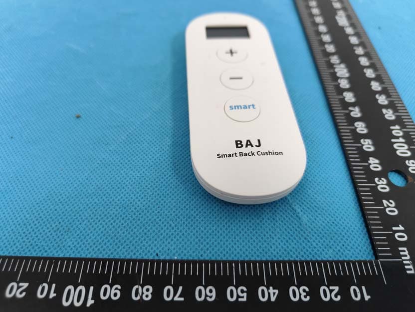
Click to zoom
Application Details
- Equipment Class
- DXX - Part 15 Low Power Communication Device Transmitter
- Date of Grant
- Jun 27, 2023
- Application Purpose
- Original Equipment
- Date of Application
- Jun 27, 2023
- Equipment Note
- Remote Control
- Frequency Range
- 2460.00000000 - 2460.00000000
- Country
- China
Documents & Files
Document Text
Text extracted from the exhibit documents filed with the FCC. Open a document above to read the original.
Users Manual
Smart Back Cushion User Manual Table of Contents Page 1 .................................................................................218 Summary .........................................................................154.1 Get Ready .......................................................164.2 Recall your Sitting Number 1 Included in the box ........................................................................2 ........................................................................32 Product at a glance 7 ...................................................................................3 First Use ....................................73.1 Charge Smart Back Cushion Before First Use .......................................................................83.2 Preparation ...........................................................................93.3 Inflating ..........................................................................113.4 Deflating ...............................................................123.5 Set Up Smart Mode ...................................................................133.6 Remote Control ............................................................143.7 Turn off Automatically .................................................................143.8 Turn off Manually ...................................................................................154 Daily Use ........................................................................... 175 Charging Weekly ........................................................................196 Reset Smart Mode ......................................................... 207 Change Battery of Remote Control 1 Included in the box Smart Back Cushion Model: BAJBC11 Remote Control Model: BC11-C USB-C CableUser Manual Page 2 2 Product at a glance Page 3 Smart Back Cushion USB-C Charging Port Status Light of Smart Back Cushion Power Button Page 4 Remote Control Battery Cover Screen Status Light of Remote Control Smart Mode Button “ + ” Button “ - ” Button Page 5 Sitting Number Shown on ScreenInflation Level of Smart Back Cushion Page 6 Sitting Number Shown on ScreenInflation Level of Smart Back Cushion 3 First Use Page 7 3.1 Charge Smart Back Cushion Before First Use 1. Plug USB-C Cable into USB-C Charging Port. Connect Smart Back Cushion to a power outlet using USB-C Cable (included) and a power outlet (not included). Smart Back Cushion would automatically deflate for several seconds. 2. While charging, Status Light of Smart Back Cushion keeps flashing green. 3. Once fully charged, Status Light of Smart Back Cushion turns solid green. Charging: Fully charged: 4. Put Smart Back Cushion on a chair, and sit on the chair. Light blue side of cushion should face toward you; the tag should be at your left side; the power button should be at your right side. Page 8 3.2 Preparation 1. Have Smart Back Cushion and Remote Control ready. 2. Pull out the insulation sheet at the back of Remote Control. Screen of Remote Control would light up and show “00”. Remote Control is on. BAJ Smart Back Cushion smart pause Pull 3. Long press Power Button of Smart Back Cushion for 2 seconds. Status Light of Smart Back Cushion turns solid green. Smart Back Cushion is on. 2s Page 9 3.3 Inflating 1. Hold Remote Control in your right hand. Turn on Remote Control by firmly pressing “+” button of Remote Control. 3. As a response, Smart Back Cushion starts inflating for several seconds until it gets to the next inflation level. Status Light of Smart Back Cushion keeps flashing during the process. Inflation Level Sitting Number Inflation Level Sitting Number Inflating: BAJ Smart Back Cushion smart pause 2. Press “+” button of Remote Control firmly. Status Light of Remote Control flashes green once. Sitting Number shown on Screen will change from “00” to “01”. BAJ Smart Back Cushion smart pause Page 10 4. Press “+” button of Remote Control several times, Sitting Number can go up to “10”, which is the highest inflation level. 5. The inflation level ranges from “00” to “10”: “00” indicates the lowest inflation level; “10” indicates the highest inflation level. The higher inflation level is, the firmer support you will get from Smart Back Cushion. Refer to Page 5 and Page 6 for details. 6. The inflation process could take up to 2 minutes. During the process, sit on the chair, feel the lumbar support from Smart Back Cushion. Inflation Level Sitting Number Page 11 3.4 Deflating 1. You can also press “-” button of Remote Control firmly to deflate Smart Back Cushion, if you want to try softer lumbar support. Status Light of Remote Control flashes green once. Sitting Number shown on Screen will change from “10” to “09”. 3. You can use “+” and “-” to control the inflation / deflation until you find your perfect sitting number. Let’s assume it’s “06”, and the rest of the user manual will use “06” for demo purpose. 2. As a response, Smart Back Cushion starts deflating for several seconds. Status Light of Smart Back Cushion keeps flashing during the process. Deflating: Inflation Level Sitting Number Inflation Level Sitting Number BAJ Smart Back Cushion smart pause Page 12 3.5 Set Up Smart Mode 1. If you are happy with the Sitting Number you are currently enjoying, you can use Smart Mode of Smart Back Cushion. Your Sitting Number is remembered, and can be recalled later. Smart Back Cushion would inflate to the corresponding inflation level when you recall your Sitting Number. 2. Long press Smart Button of Remote Control for 3 seconds. The “smart” icon on the screen flashes three times, and then turns solid. Smart Mode is on. Your favorite Sitting Number is remembered by Smart Back Cushion. BAJ Smart Back Cushion smart pause BAJ Smart Back Cushion smart pause smart Smart Mode setting: smartsmartsmart 3s Inflation Level Sitting Number Page 13 3.6 Remote Control You do not need to turn off the Remote Control. Just leave it as it is. 1. With no further operation of Remote Control,…
Text truncated - open the document above for the full version.
Attestation Statements
YACCA MEDICAL (SHENZHEN) CO., LTD Add: 301. 401, BLOCK 117, MINSHENG INDUSTRIAL ZONE, SHANGCUN, GUANGMING, SHENZHEN,China Tel: 0755-26655922 Mail: [email protected] CFR 47 §2.911(d)(5)(i)(ii) Attestation Letter Attestation Letter Date: 06-13-2023 FEDERAL COMMUNICATIONS COMMISSIONS Authorization and Evaluation Division 7435 Oakland Mills Road Columbia, MD 21046 Ref: Attestation Statements CFR 47 §2.911(d)(5)(i)(ii) Filing FCC ID: 2A99N-BC11-C YACCA MEDICAL (SHENZHEN) CO., LTD certifies that the equipment for which authorization is sought is not “covered” equipment prohibited from receiving an equipment authorization pursuant to section 2.903 of the FCC rules. YACCA MEDICAL (SHENZHEN) CO., LTD certifies that as of the date of the filing of the application, the applicant is not identified on the Covered List as an entity producing “covered” equipment. Sincerely, Signature Contact Person: Yangsong Zhang Title: Engineer
Attestation Statements
CFR 47 §2.911(d)(7) U.S Agent U.S. AGENT LETTER OF ATTESTATION Date: 2023-06-13 FEDERAL COMMUNICATIONS COMMISSION Authorization and Evaluation Division 7435 Oakland Mills Road Columbia, MD 21046 Ref: Attestation Statements Part 2.911(d)(7) Filing FCC ID: 2A99N-BC11-C YACCA MEDICAL (SHENZHEN) CO., LTD certifies that, as of the date of the filing of the application, ETCHMED LLC is our designated U.S. agent for service of process for the above referenced FCC ID. YACCA MEDICAL (SHENZHEN) CO., LTD accepts to maintain an agent for no less than one year after the grantee has terminated all marketing and importation or the conclusion of any Commission-related proceeding involving the equipment. ETCHMED LLC accepts, as of the date of the filing of the application, the obligation of the designated U.S. agent for service of process for the above referenced FCC ID. Designated U.S. Agent Information: Company Name: ETCHMED LLC Address: 12 TOSCANY, IRVINE,CALIFORNIA, 94306 United States FRN: 0033644675 Tel.: 669609791 Email: [email protected] Signed by (printed name): Ling Bai Signature: Applicant: YACCA MEDICAL (SHENZHEN) CO., LTD Add: 301. 401, BLOCK 117, MINSHENG INDUSTRIAL ZONE, SHANGCUN, GUANGMING, SHENZHEN,China Tel: 0755-26655922 Email: [email protected] Signed by (printed name): Yangsong Zhang Signature:
Cover Letter(s)
QA-FR-170-B YACCA MEDICAL (SHENZHEN) CO., LTD ADD: 301. 401, BLOCK 117, MINSHENG INDUSTRIAL ZONE, SHANGCUN, GUANGMING, SHENZHEN,China TEL: 0755-26655922 E-mail: [email protected] FCC Authorization Date: 2023-06-13 FEDERAL COMMUNICATIONS COMMISSION Authorization and Evaluation Division 7435 Oakland Mills Road Columbia, MD 21046 Subject: Agent Authorization To whom it may concern: We , YACCA MEDICAL (SHENZHEN) CO., LTD, Hereby authorizes China Certification ICT Co., Ltd (Dongguan) to act on its behalf in all matters relating to application for Equipment authorization, including the signing of all documents relating to these matters. All acts carried out by China Certification ICT Co., Ltd (Dongguan) on our behalf shall have the same effect as our own action. We, the undersigned, hereby certify that we are not subject to a denial of federal benefits, that includes FCC benefits, pursuant to Section 5301 of the Anti-Drug Abuse Act of 1988, 21 U.S.C. 862. This authorization is valid until further written notice from the applicant. Sincerely Yours, Client’s signature Printed Name: Yangsong Zhang Title: Engineer
Cover Letter(s)
QA-FR-171-A YACCA MEDICAL (SHENZHEN) CO., LTD ADD: 301. 401, BLOCK 117, MINSHENG INDUSTRIAL ZONE, SHANGCUN, GUANGMING, SHENZHEN,China TEL: 0755-26655922 E-mail: [email protected] FCC Confidential Authorization Date: 2023-06-13 FEDERAL COMMUNICATIONS COMMISSIONS Authorization and Evaluation Division 7435 Oakland Mills Road Columbia, MD 21046 Subject: Confidentiality Request regarding application for certification of FCC ID: 2A99N-BC11-C In accordance with Sections 0.457 and 0.459 of the Commission’s Rules, YACCA MEDICAL (SHENZHEN) CO., LTD hereby requests long-term confidential treatment of information accompanying this application as outlined below: Block Diagram Schematics Operation Description The above materials contain proprietary and confidential information not customarily released to the public. The public disclosure of these materials provides unjustified benefits to its competitors in the market. Sincerely, Signature: Printed Name: Yangsong Zhang Title: Engineer
External Photos
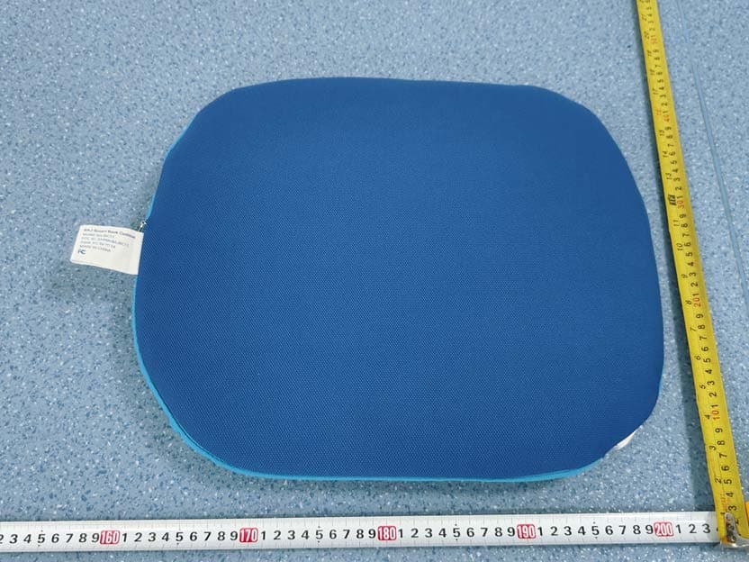
EXHIBIT B - EUT EXTERNAL PHOTOGRAPHS
Internal Photos
EXHIBIT C - EUT INTERNAL PHOTOGRAPHS Chip Antenna
RF Exposure Info
China Certification ICT Co., Ltd (Dongguan) Report No.: CR230101033-00A Page 28 of 28 5. RF EXPOSURE EVALUATION 5.1 Applicable Standard FCC §1.1307(b)(3)(i)(A) a single RF source is exempt RF device (from the requirement to show data demonstrating compliance to RF exposure limits, as previously mentioned) if the available maximum time-averaged power is no more than 1 mW, regardless of separation distance. 5.2 Procedure According to 447498 D04 Interim General RF Exposure Guidance v01, clause 2.1.2- 1-mW Test Exemption: Per §1.1307(b)(3)(i)(A), a single RF source is exempt RF device (from the requirement to show data demonstrating compliance to RF exposure limits, as previously mentioned) if the available maximum time-averaged power is no more than 1 mW, regardless of separation distance. This exemption applies to all operating configurations and exposure conditions, for the frequency range 100 kHz to 100 GHz, regardless of fixed, mobile, or portable device exposure conditions. This is a standalone exemption, and it cannot be applied in conjunction with any other test exemption. 5.3 Measurement Result Frequency (MHz) Maximum ERP Power 1-mW Test Exemption dBm mW 2460 -2.37 0.58 Compliant Note: 1. Chose the maximum power to do MPE analysis. 2. This device maximum E-Field level is 94.98 dBμV/m at 3m, so the EIRP power is -0.22 dBm. 3. EIRP(dBm)=Field Strength of Fundamental(dBuV/m)-95.2 4. ERP(dBm)= EIRP(dBm)-2.15dB Result: Compliant. RF Exposure is exemption. ===== END OF REPORT =====
Test Report
TEST REPORT Applicant: YACCA MEDICAL (SHENZHEN) CO., LTD Address: 301. 401, BLOCK 117, MINSHENG INDUSTRIAL ZONE, SHANGCUN, GUANGMING, SHENZHEN,China FCC ID: 2A99N-BC11-C Product Name: Remote Control Model: BC11-C Standard(s): 47 CFR Part 15, Subpart C(15.249) ANSI C63.10-2013 The above equipment has been tested and found compliant with the requirement of the relative standards by China Certification ICT Co., Ltd (Dongguan) Report Number: CR230101033-00A Date Of Issue: 2023/6/6 Reviewed By: Sun Zhong Title: Manager Test Laboratory: China Certification ICT Co., Ltd (Dongguan) No. 113, Pingkang Road, Dalang Town, Dongguan, Guangdong, China Tel: +86-769-82016888 China Certification ICT Co., Ltd (Dongguan) Report No.: CR230101033-00A Page 2 of 28 Test Facility The Test site used by China Certification ICT Co., Ltd (Dongguan) to collect test data is located on the No. 113, Pingkang Road, Dalang Town, Dongguan, Guangdong, China. The lab has been recognized as the FCC accredited lab under the KDB 974614 D01 and is listed in the FCC Public Access Link (PAL) database, FCC Registration No. : 442868, the FCC Designation No. : CN1314. The lab has been recognized by Innovation, Science and Economic Development Canada to test to Canadian radio equipment requirements, the CAB identifier: CN0123. Declarations China Certification ICT Co., Ltd (Dongguan) is not responsible for the authenticity of any test data provided by the applicant. Data included from the applicant that may affect test results are marked with a triangle symbol “▲”. Customer model name, addresses, names, trademarks etc. are not considered data. Unless otherwise stated the results shown in this test report refer only to the sample(s) tested. This report cannot be reproduced except in full, without prior written approval of the Company. This report is valid only with a valid digital signature. The digital signature may be available only under the Adobe software above version 7.0. This report may contain data that are not covered by the accreditation scope and shall be marked with an asterisk “★”. China Certification ICT Co., Ltd (Dongguan) Report No.: CR230101033-00A Page 3 of 28 CONTENTS T EST FACILITY .......................................................................................................................................... 2 DECLARATIONS .......................................................................................................................................... 2 DOCUMENT REVISION HISTORY........................................................................................... 5 1. GENERAL INFORMATION .................................................................................................... 6 1.1 PRODUCT DESCRIPTION FOR EQUIPMENT UNDER TEST (EUT) ....................................................... 6 1.2 DESCRIPTION OF TEST CONFIGURATION ........................................................................................... 7 1.2.2 Support Equipment List and Details .............................................................................................................. 7 1.2.3 Support Cable List and Details ...................................................................................................................... 7 1.2.4 Block Diagram of Test Setup ......................................................................................................................... 7 1.3 MEASUREMENT UNCERTAINTY .......................................................................................................... 8 2. SUMMARY OF TEST RESULTS ............................................................................................ 9 3. REQUIREMENTS AND TEST PROCEDURES .................................................................. 10 3.1 AC LINE CONDUCTED EMISSIONS .................................................................................................... 10 3.1.1 Applicable Standard ..................................................................................................................................... 10 3.1.2 EUT Setup .................................................................................................................................................... 11 3.1.3 EMI Test Receiver Setup ............................................................................................................................. 11 3.1.4 Test Procedure ............................................................................................................................................. 12 3.1.5 Corrected Amplitude & Margin Calculation ................................................................................................ 12 3.2 RADIATED EMISSIONS ....................................................................................................................... 13 3.2.1 Applicable Standard ..................................................................................................................................... 13 3.2.2 EUT Setup .................................................................................................................................................... 13 3.2.3 EMI Test Receiver & Spectrum Analyzer Setup ......................................................................................... 14 3.2.4 Test Procedure ............................................................................................................................................. 14 3.2.5 Corrected Amplitude & Margin Calculation ................................................................................................ 15 3.3 20 DB EMISSION BANDWIDTH: .......................................................................................................... 16 3.3.1 Applicable Standard ..................................................................................................................................... 16 3.3.2 EUT Setu…
Text truncated - open the document above for the full version.
Test Setup Photos
EXHIBIT D - TEST SETUP PHOTOGRAPHS Radiated Emission Below 1GHz View Radiated Emission Above 1GHz View
Contact Information
Applicant
YangSong Zhang(Engineer)
Test Firm
CHINA CERTIFICATION ICT CO., LTD (DONGGUAN)Tanie Ou
[email protected]0086 0769 86858888
Technical Specifications
| # | Rule Parts | Frequency Range | Power Output |
|---|---|---|---|
| 1 | 15C | 2.46 GHz - 2.46 GHz | - |
Other Applications from YACCA MEDICAL (SHENZHEN) CO., LTD
2A99N-BAJBC11
Jun 27, 2023Smart Back Cushion
Equipment Class
DXX - Part 15 Low Power Communication Device Transmitter