2A99V-CST88CST-88 Modem
Jacobs Technology Inc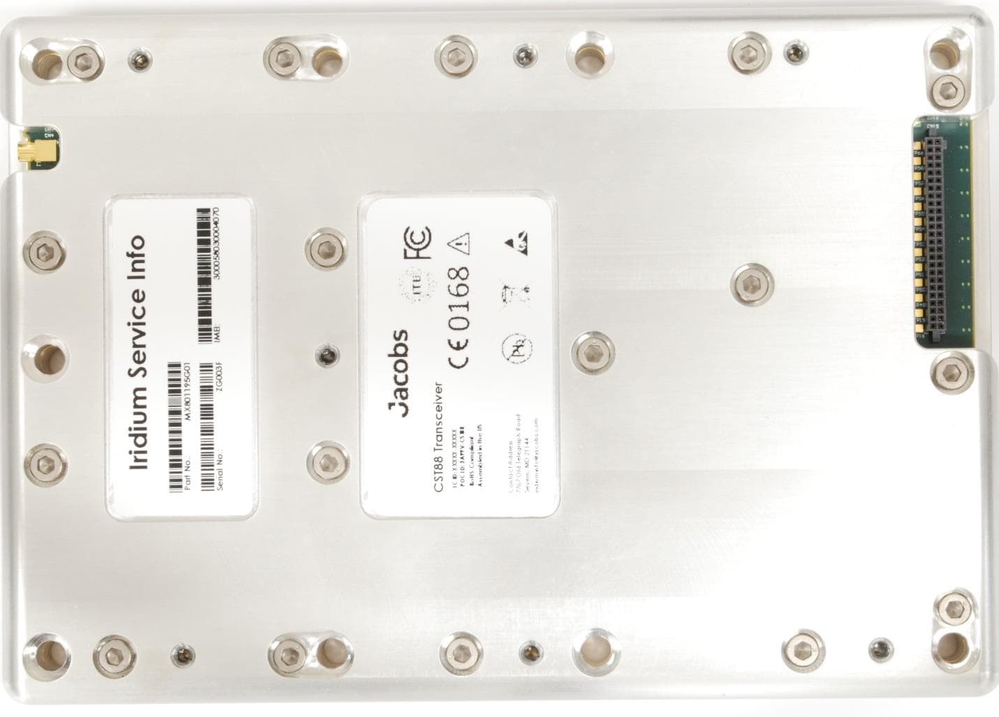
Click to zoom
Application Details
- Equipment Class
- TNB - Licensed Non-Broadcast Station Transmitter
- Date of Grant
- Jul 26, 2023
- Application Purpose
- Original Equipment
- Date of Application
- Jul 26, 2023
- Equipment Note
- CST-88 Modem
- Frequency Range
- 1616.00000000 - 1626.00000000
- Company
- Jacobs Technology Inc
- Country
- United States
Documents & Files
Document Text
Text extracted from the exhibit documents filed with the FCC. Open a document above to read the original.
Users Manual
Jacobs Certus™ CST-88 User Guide March 2023 Jacobs Certus™ CST-88 | V00 Proprietary Confidential | 1 Controlled for export under the EAR as set forth in the LEGAL DISCLAIMER AND CONDITIONS OF USE. Contents Revision History ...................................................................................................................................................................... 4 1 Introduction .................................................................................................................................................................... 5 1.1 Intended Audience .................................................................................................................................................. 5 1.2 Reference Documents ............................................................................................................................................. 5 1.3 Abbreviations .......................................................................................................................................................... 6 2 Digital Interface ............................................................................................................................................................... 7 2.1 Digital Connector .................................................................................................................................................... 7 2.2 Pin Locations ........................................................................................................................................................... 7 2.3 Pinout Descriptions ................................................................................................................................................. 9 2.4 Digital Input/Output .............................................................................................................................................. 12 2.5 ESD Protection ...................................................................................................................................................... 12 2.6 Power Supply ........................................................................................................................................................ 12 2.7 Power Consumption.............................................................................................................................................. 12 2.8 Power On Control.................................................................................................................................................. 13 2.9 Power Off Control ................................................................................................................................................. 15 2.10 Phantom Powering ............................................................................................................................................ 16 2.11 Serial Ports ........................................................................................................................................................ 16 2.12 Digital Audio Interface ...................................................................................................................................... 16 2.13 SIM Interface ..................................................................................................................................................... 16 2.14 Power Saving Features ...................................................................................................................................... 17 2.15 Transmit Indicator ............................................................................................................................................. 17 2.16 Diagnostic Interface .......................................................................................................................................... 17 3 RF Interface ................................................................................................................................................................... 19 3.1 RF Connector Type ................................................................................................................................................ 19 3.2 General RF Specifications ...................................................................................................................................... 19 3.3 Conducted RF Interface......................................................................................................................................... 19 3.4 RF Path Considerations ......................................................................................................................................... 19 3.5 ESD Protection ...................................................................................................................................................... 20 4 Mechanical Specifications ............................................................................................................................................. 21 4.1 Size & Mass ........................................................................................................................................................... 21 4.2 Enclosure Material ................................................................................................................................................ 21 4.3 Mechanical Drawing.............................................................................................................................................. 21 4.4 Mounting Considerations...................................................................................................................................... 22 4.5 Grounding .............................................................................................................…
Text truncated - open the document above for the full version.
Attestation Statements
Jacobs Technology Inc. 7767 Old Telegraph Road Address 3 Severn, MD 21144 www.jacobs.com Certification Application Attestation Statements Date: March 1, 2023 American Certification Body, Inc. 313 Park Avenue Suite 300 Falls Church, VA 22046 Statement for 47 CFR section 2.911(d)(5)(i) ______Jacobs Technology Inc.______ certifies that as of the date of the application the equipment for which authorization is sought is not “covered” equipment 1 prohibited from receiving an equipment authorization pursuant to section 2.903 of the FCC rules. If the equipment for which the applicant seeks authorization is produced by any of the entities identified on the current Covered List, including affiliates or subsidiaries of the named companies, the applicant must include an explanation on why the equipment is not “covered” equipment. Additional Explanation: <N/A> Statement for 47 CFR section 2.911(d)(5)(ii) ______Jacobs Technology Inc.______ (“the applicant”) certifies that, as of the date of the filing of this application, the applicant ☐ - is / ☒ - is not identified on the Covered List as an entity producing “covered” equipment. Thank you, By: Scott E. Donaldson (Signature) (Print name) Title: Program Manager Company: Jacobs Technology Inc. (Company Name) Telephone: +1.937.979.0148
Attestation Statements
06 Jacobs Technology Inc. 7767 Old Telegraph Road Severn, MD 21144 www.jacobs.com Date: 24 July 2023 American Certification Body 313 Park Avenue Falls Church, VA 22046 ATTENTION: FCC Certification – Section 2.911(d)(7) Information This letter is to confirm that the Applicant will also serve as the U.S. Agent for Service of Process as required by 47 CFR 2.911(d)(7). The Applicant acknowledges that they must maintain an agent for no less than one year after terminating all marketing and importation OR the conclusion of any Commission-related proceeding involving the equipment. The Applicant further acknowledges their responsibility to inform the FCC whenever the Designated U.S. Agent information changes. Applicant Company name: Jacobs Technology Inc FRN #: 0033404658 Grantee Code: 2A99V Contact Name: Scott Donaldson Street Address: 7767 Old Telegraph Road City/Province/Zip: Severn, MD 21144 Telephone No: (937) 979-0148 Email: [email protected] Applicant Signature: Date: 24 July 2023 Signed by (Printed Name/Title): Scott E. Donaldson, PM
Attestation Statements
July 26, 2023 Jacobs Technology Inc., 7765 Old Telegraph Rd Severn, MD 21144 Re: Iridium Letter of Authorization for Access to the Iridium Constellation NON-EXCLUSIVE LETTER OF AUTHORIZATION Iridium Satellite LLC (“Iridium”) confirms the Jacobs CST 88 Transceiver has been deemed as “Iridium Compatible Equipment” (“ICE”) certified to access the Iridium communications system (“ICS”). Products incorporating ICE must undergo and pass an Iridium Certification process to allow that particular product access to the ICS. Iridium airtime services are made available to duly authorized Iridium partner service providers (SPs) and/or Value-Added Resellers (“VAR”) in good standing, in accordance with the terms of the applicable Iridium Global Service Provider Agreement or Value- Added Reseller Agreement executed with such Iridium SP and/or VAR. COMMERCIAL PRODUCT CERTIFICATION Iridium certifies that Iridium satellite communications products and services are regularly offered for other than Government purposes and are sold or traded in the course of normal business operations. SPECTRUM LICENSE Iridium is a globally accessible Low Earth Orbit satellite constellation and holds the Spectrum Licenses in the United States. Sincerely, Manny Verdusco Manny Verdusco, Sr. Contracts Manager, Govt. Programs Date: July 26, 2023 END OF LETTER
Cover Letter(s)
Jacobs Technology Inc. 7767 Old Telegraph Road Address 3 Severn, MD 21144 www.jacobs.com Authority to Act as Agent Date: March 1, 2023 American Certification Body, Inc. 313 Park Avenue Suite 300 Falls Church, VA 22046 To Whom It May Concern: Kimberly Colbert is authorized to act on our behalf, until otherwise notified, for applications to American Certification Body, Inc. (ACB). We certify that we are not subject to denial of federal benefits, that includes FCC benefits, pursuant to Section 5301 of the Anti-Drug Abuse Act of 1988, 21 U.S.C. 862. Further, no party, as defined in 47 CFR 1.2002 (b), to the application is subject to denial of federal benefits, that includes FCC benefits. We also declare that the information provided to the FCC is true and correct to the best of our knowledge (47 CFR 2.911(d)) and we have been informed of the grantee responsibilities (47 CFR 2.909) with regard to certified equipment. Thank you, Agency Agreement Expiration Date: 1 March 2024 By: Scott E. Donaldson (Signature) (Print name) Title: Program Manager On behalf of: Jacobs Technology Inc. (Company Name) Telephone: +1.937.979.0148
Cover Letter(s)
Jacobs Technology Inc. 7767 Old Telegraph Road Address 3 Severn, MD 21144 www.jacobs.com Request for Confidentiality Date: March 10, 2023 Subject: Confidentiality Request for: 2A99V-CST88 & 30125-CST88 Pursuant to FCC 47 CFR 0.457(d) and 0.459 and/or IC RSP-100, Section 12.4, the applicant requests that a part of the subject application(s) be held confidential. Type of Confidentiality Requested Exhibit ☐ Short Term ☒ Permanent Block Diagrams ☒ Short Term --------------------------- External Photos ☒ Short Term ☐ Permanent Internal Photos ☐ Short Term ☒ Permanent Operation Description/Theory of Operation ☐ Short Term ☒ Permanent Parts List & Placement/BOM ☐ Short Term ☒ Permanent Tune-Up Procedure ☐ Short Term ☒ Permanent Schematics ☐ Short Term --------------------------- Test Setup Photos ☒ Short Term ☐ Permanent User’s Manual Jacobs Technology Inc. has spent substantial effort in developing this product and it is one of the first of its kind in industry. Having the subject information easily available to "competition" would negate the advantage they have achieved by developing this product. Not protecting the details of the design will result in financial hardship. Permanent Confidentiality: The applicant requests the exhibits listed above as permanently confidential be permanently withheld from public review due to materials that contain trade secrets and proprietary information not customarily released to the public. Short-Term Confidentiality for FCC Applications: The applicant requests the exhibits selected above as short term confidential be withheld from public view for a period of __180___ days from the date of the Grant of Equipment Authorization and prior to marketing. This is to avoid premature release of sensitive information prior to marketing or release of the product to the public. Applicant is also aware that they are responsible to notify ACB in the event information regarding the product or the product is made available to the public before the requested period has expired. ACB will then release the documents listed above for public disclosure pursuant to FCC Public Notice DA 04-1705. Short Term Confidentiality for Industry Canada Applications: Starting May 2022, ISED will recognize short term confidentiality on certain exhibits until the intended date of marketing. The applicant requests the exhibits selected above as short term confidential be withheld from public view until: (specify ISED expiration date/date of marketing). Sincerely By: Scott E. Donaldson (Signature/Title) (Print name)
Cover Letter(s)
Jacobs Technology Inc. 7767 Old Telegraph Road Severn, MD 21144 www.jacobs.com Date: 23 May 2023 American Certification Body 313 Park Avenue Falls Church, VA 22046 Request for Modular/Limited Modular Approval Subject: Manufacturer’s Declaration for ☒ - Modular Approval ☐ - Split Modular Approval ☐ - Limited Modular Approval ☐ - Limited Split Modular Approval Confidentiality Request for: ______2A99V-CST88______ 8 Basic Requirements – FCC Part 15.212(a)(1) For Items Marked “NO(*)”, the Limited Module Description Must be Filled Out on the Following Pages Modular Approval Requirement Requirement Met 1. The modular transmitter must have its own RF shielding. This is intended to ensure that the module does not have to rely upon the shielding provided by the device into which it is installed in order for all modular transmitter emissions to comply with FCC limits. It is also intended to prevent coupling between the RF circuitry of the module and any wires or circuits in the device into which the module is installed. Such coupling may result in non-compliant operation. The physical crystal and tuning capacitors may be located external to the shielded radio elements. 15.212(a)(1)(i) ☒ - YES ☐ - NO(*) Details: The module incorporates a metal housing/enclosure to shield the circuitry from the environment and vice versa. The enclosure covers all power supply, digital, analog, and RF components and circuitry. The shield/enclosure is located on the top and bottom of the PCA and envelops the board and its circuitry. Only the connectors are exposed to the environment. 2. The modular transmitter must have buffered modulation/data inputs (if such inputs are provided) to ensure that the module will comply with FCC requirements under conditions of excessive data rates or over-modulation. 15.212(a)(1)(ii) ☒ - YES ☐ - NO(*) Details: Data to the modulation circuit is buffered as described in the operational description provided with the application. The data rate and modulation are controlled and limited by the modular transmitter and cannot be changed or increased beyond its design by the user. 3. The modular transmitter must have its own power supply regulation on the module. This is intended to ensure that the module will comply with FCC requirements regardless of the design of the power supplying circuitry in the device into which the module is installed. 15.212(a)(1)(iii) ☒ - YES ☐ - NO(*) Details: The module contains its own power supply regulation. Please refer to schematic filed with this application. 4. The modular transmitter must comply with the antenna and transmission system requirements of §§ 15.203, 15.204(b), 15.204(c), 15.212(a), and 2.929(b). The antenna must either be permanently attached or employ a ‘‘unique’’ antenna coupler (at all connections between the module and the antenna, including the cable). The ‘‘professional installation’’ provision of § 15.203 is not applicable to modules but can apply to limited modular approvals under paragraph 15.212(b). 15.212(a)(1)(iv) ☒ - YES ☐ - NO(*) Details: The module connects to its antenna using an MMCX connector which is considered a non-standard connector. A list of antennas tested and approved with this device may be found in user’s manual provided with the application. 5. The modular transmitter must be tested in a stand-alone configuration, i.e., the module must not be inside another device during testing. This is intended to demonstrate that the module is capable of complying with Part 15 emission limits regardless of the device into which it is eventually installed. Unless the transmitter module will be battery powered, it must comply with the AC line conducted requirements found in Section 15.207. AC or DC power lines and data input/output lines connected to the module must not contain ferrites, unless they will be marketed with the module (see Section 15.27(a)). The length of these lines shall be length typical of actual use or, if that length is unknown, at least 10 centimeters to insure that there is no coupling between the case of the module and supporting equipment. Any accessories, peripherals, or support equipment connected to the module during testing shall be unmodified or commercially available (see Section 15.31(i)). 15.212(a)(1)(v) ☒ - YES ☐ - NO(*) Details: The module was tested stand-alone as shown in test setup photographs filed with this application. To control and test the transmitter, an HDK adapter PCA is used to adapt the module to a PC via USB and to supply DC power. Modular Approval Requirement Requirement Met 6. The modular transmitter must be labeled with its own FCC ID number, or use an electron display (see KDB Publication 784748). If using a permanently affixed label with its own FCC ID number, if the FCC ID is not visible when the module is installed inside another device, then the outside of the device into which the module is installed must also display a label referring to the enclosed module. This exterior label can use wording such as the following: “Contains Transmitter Module FCC ID: XYZMODEL1” or “Contains FCC ID: XYZMODEL1.” Any similar wording that expresses the same meaning may be used. The Grantee may either provide such a label, an example of which must be included in the application for equipment authorization, or, must provide adequate instructions along with the module which explain this requirement. In the latter case, a copy of these instructions must be included in the application for equipment authorization. If the modular transmitter uses an electronic display of the FCC identification number, the information must be readily accessible and visible on the modular transmitter or on the device in which it is installed. If the module is installed inside another device, then the outside of the device into which the module is installed must display a label referring to the enclosed module. This exterior label can use wording such as the following: “Contains FCC certified transmitter module(s).” Any…
Text truncated - open the document above for the full version.
Cover Letter(s)
06 Jacobs Technology Inc. 7767 Old Telegraph Road Severn, MD 21144 www.jacobs.com Date: 20 July 2023 American Certification Body 313 Park Avenue Falls Church, VA 22046 Subject: Certification of Equipment under the FCC Equipment Authorization Program To Whom It May Concern: Enclosed, please find a radio application from Jacobs requesting the certification of the CST88 under Part 25 of the Federal Communication Commission’s Rules. Below is the relevant information regarding the above noted device - FCC ID : _2A99V-CST88_ FCC Rule Applied: ______47 C.F.R. Part 25_______ We have enclosed the completed the application form with the applicable exhibits. Please note that Jacobs is aware of the fact that certification is not required for this device, however, we have chosen to pursue it, nonetheless, as permitted by KDB 273109)item 2). If you have any questions or need any additional information, please let me know. Sincerely, By: Scott E. Donaldson (Signature) (Print name) Title: Program Manager On behalf of: Jacobs Technology Inc. (Company Name) Telephone: +1(937) 979-0148
External Photos
Top Side1 Side2 End1 End2 Bottom
ID Label/Location Info
2.00 1.20 4 5 6 7 3 .002 P/N: MX801199P01 NOTES: MATERIAL: B-727 POLYIMIDE1. MAKE FROM BRADY PART NUMBER Y50704412. JACOBS LOGO: THERMAL TRANSFER PRINT TEXT ALIGNED AS SHOWN 3 USING JACOBS STANDARD PRINT LOGO AT .175 INCHES HIGH DEVICE NAME: THERMAL TRANSFER PRINT DEVICE NAME ALIGNED AS 4 SHOWN. USE CENTURY GOTHIC REGULAR FONT .06 INCHES HIGH. CST88 PART NUMBER IS MX801195G01 THERMAL TRANSFER PRINT TEXT ALIGNED AS SHOWN USING CENTURY 5 GOTHIC REGULAR FONT .03 INCHES HIGH. IC ID AND FCC ID ARE DEFINED BY PURCHASE ORDER CONTACT ADDRESS: THERMAL TRANSFER PRINT TEXT ALIGNED AS 6 SHOWN. USE CENTURY GOTHIC REGULAR FONT .03 INCHES HIGH SYMBOLS: THERMAL TRANSFER PRINT SYMBOLS (7 TOTAL) IN 7 LOCATIONS AND SIZE AS SHOWN BAG AND TAG LABEL WITH PART NUMBER AND REVISION8. ALL LABEL MATERIALS SHALL BE RoHS COMPLIANT9. REVISIONS REV.DESCRIPTIONDATEECOBYAPPD 03INITIAL RELEASE3/25/2021N/AEKBC 04 UPDATE PER TOM EDMONSTON INPUT 8/17/2021N/ABCKG 05 UPDATE TO NOTES AND FLAG NOTE CALLOUTS 3/9/2022N/AKGBC A B C D 12345678 2 3 4 5 6 7 A B C D CAD FILE: MX801199 DRW FILE: MX801199 1 LAST SAVED ON 2023-03-10 11:55:04 AM THIS DOCUMENT IS PROPRIETARY TO, COMMERCIALLY SENSITIVE TO, AND WHOLLY OWNED BY JACOBS. ANY UNAUTHORIZED REVIEW, DISCLOSURE, USE OR DISTRIBUTION OF THE INFORMATION CONTAINED HEREIN IS PROHIBITED. THIS DOCUMENT SHALL NOT BE DISTRIBUTED TO ANY PARTY OTHER THAN THE EXPLICITLY IDENTIFIED INTENDED PARTY WITHOUT THE EXPRESS WRITTEN AUTHORIZATION OF JACOBS. PROPRIETARY AND CONFIDENTIAL INTERPRET DIMENSIONS PER ASME Y14.5 - 2018 UNLESS OTHERWISE NOTED: .01 .005 0.5 .03 SURFACE FINISH 63 DIMENSIONS APPLY AFTER FINISH DIMENSIONS ARE IN THIRD ANGLE PROJECTION TOLERANCES INCHES X.XXX X.XX X.X X AS NOTED N/A 2021-03-25 2021-03-25 B. COLE B. COLE E. KEATING2021-03-04 PM RESP ENGINEER DESIGNER DRAWNDATE DATE DATE DATE FINISH MATERIAL DESCRIPTION CST88 REGULATORY LABEL PROJECT CAGE CODE 8LJL8 CAD REV:DO NOT SCALE DRAWING 05 MX801199 DWG NO. BSIZE:SCALE: REV 3:1 SHEET SOLIDWORKS 1 OF 1 05 Released - Informal
ID Label/Location Info
.80 .30 4X R.080 3 .002 P/N: MX801200P01 NOTES: MATERIAL: B-727 POLYIMIDE1. MAKE FROM BRADY PART NUMBER Y50704422. THERMAL TRANSFER PRINT TEXT SHOWN USING .05 HIGH GOTHIC 3 CHARACTERS BAG AND TAG LABEL WITH PART NUMBER AND REVISION4. ALL LABEL MATERIALS SHALL BE RoHS COMPLIANT5. REVISIONS REV.DESCRIPTIONDATEECOBYAPPD 03INITIAL RELEASE3/26/2021-EKBC 04 UPDATE PER TOM EDMONSTON INPUT 8/17/2021-BCKG 05 UPDATES TO NOTES AND FLAG NOTE CALLOUTS 3/9/2022-KGBC A B C D 12345678 2 3 4 5 6 7 A B C D CAD FILE: MX801200 DRW FILE: MX801200 1 LAST SAVED ON 4/12/2022 1:41:02 PM THIS DOCUMENT IS PROPRIETARY TO, COMMERCIALLY SENSITIVE TO, AND WHOLLY OWNED BY JACOBS. ANY UNAUTHORIZED REVIEW, DISCLOSURE, USE OR DISTRIBUTION OF THE INFORMATION CONTAINED HEREIN IS PROHIBITED. THIS DOCUMENT SHALL NOT BE DISTRIBUTED TO ANY PARTY OTHER THAN THE EXPLICITLY IDENTIFIED INTENDED PARTY WITHOUT THE EXPRESS WRITTEN AUTHORIZATION OF JACOBS. PROPRIETARY AND CONFIDENTIAL INTERPRET DIMENSIONS PER ASME Y14.5 - 2018 UNLESS OTHERWISE NOTED: .01 .005 0.5 .03 SURFACE FINISH 63 DIMENSIONS APPLY AFTER FINISH DIMENSIONS ARE IN THIRD ANGLE PROJECTION TOLERANCES INCHES X.XXX X.XX X.X X AS NOTED N/A 3/26/2021 3/26/2021 - B. COLE B. COLE E. KEATING3/4/2021 PM RESP ENGINEER DESIGNER DRAWNDATE DATE DATE DATE FINISH MATERIAL DESCRIPTION CST88 TAMPER EVIDENT LABEL PROJECT CAGE CODE 8LJL8 CAD REV:DO NOT SCALE DRAWING 05 MX801200 DWG NO. BSIZE:SCALE: REV 8:1 SHEET SOLIDWORKS 1 OF 1 05 Released - Informal
ID Label/Location Info
ISOMETRIC VIEWINVERTED ISOMETRIC VIEW CST88 DIGITAL CONNECTOR CST88 MOUNTING HOLES TYPICAL 9 PLACES TAMPER EVIDENT LABEL SERVICE INFORMATION LABEL REGULATORY LABEL APPLICATION BOARD MOUNTING HOLES TYPICAL 7 PLACES RF CONNECTOR MOUNTING SURFACE 4 (MOUNTING HOLES TYPICAL 9 PLACES) TAMPER EVIDENT LABEL JACOBS ASSY P/N: MX801195G01 NOTES: MAXIMUM WEIGHT: 1.20 LBS (545 GRAMS).1. RECOMMENDED CST88 MOUNTING HARDWARE:2 9 EA NAS1352N08-XX SCREW, 08-32, X.XXX L, A286 SKT HD CAP SCREW RECOMMENDED TORQUE: 32.3 IN-LBS +/- 3.0 IN-LBS APPLICATION BOARD MOUNTING HARDWARE:3 7 EA 4-40, X.XXX L, SCREWS, MAXIMUM THREAD DEPTH: .212 INCHES TO PREVENT OVERHEATING OR DAMAGE TO THE MODEM, 4 THE MODEM MUST BE MOUNTED ON A COLD PLATE CAPABLE OF MAINTAINING A NOT TO EXCEED MODEM MOUNTING SURFACE TEMPERATURE OF 70 DEGREES C. REVISIONS REV.DESCRIPTIONDATEECOBYAPPD 05INITIAL RELEASE2022-02-28N/ABCKG 06 DIGITAL CONNECTOR PART NUMBER AND KEYING FEATURE CHANGE 2022-08-15N/AKGBC 07 ELIMINATED SPRING PIN THROUGH HOLES IN BOTTOM HOUSING 2022-12-28N/ABCKG A B C D 12345678 2 3 4 5 6 7 A B C D CAD FILE: MX801195 DRW FILE: MX803376 1 LAST SAVED ON 1/3/2023 10:14:57 AM THIS DOCUMENT IS PROPRIETARY TO, COMMERCIALLY SENSITIVE TO, AND WHOLLY OWNED BY JACOBS. ANY UNAUTHORIZED REVIEW, DISCLOSURE, USE OR DISTRIBUTION OF THE INFORMATION CONTAINED HEREIN IS PROHIBITED. THIS DOCUMENT SHALL NOT BE DISTRIBUTED TO ANY PARTY OTHER THAN THE EXPLICITLY IDENTIFIED INTENDED PARTY WITHOUT THE EXPRESS WRITTEN AUTHORIZATION OF JACOBS. PROPRIETARY AND CONFIDENTIAL INTERPRET DIMENSIONS PER ASME Y14.5 - 2018 UNLESS OTHERWISE NOTED: .01 .005 0.5 .03 SURFACE FINISH 63 DIMENSIONS APPLY AFTER FINISH DIMENSIONS ARE IN THIRD ANGLE PROJECTION TOLERANCES INCHES X.XXX X.XX X.X X N/A N/A 2/28/2022 2/28/2022 K. GESSLER B. COLE B. COLE2/28/2022 ENG APPROVER RESP ENGINEER DRAFTERDATE DATE DATE FINISH MATERIAL DESCRIPTION CST88 INTERFACE, MECHANICAL, CST88 PROJECT CAGE CODE 8LJL8 CAD REV:DO NOT SCALE DRAWING 07 MX803376 DWG NO. BSIZE:SCALE: REV 8:10 SHEET SOLIDWORKS 1 OF 3 Released - Informal 9X .193 + - .005 .001 THRU 0 4X .320 2.250 4X 4.180 0 3X .320 2X 2.142 2X 3.869 2X 6.1806.500 4.500 3.625 3.010 HOLES FOR CST88 MOUNTING HARDWARE DIGITAL CONNECTOR P/N: SFM-125-01-L-D 50 CONTACTS RF CONNECTOR P/N: MMCX-J-P-H-RA-TH1 MICRO-MINI RF JACK 50 OHM IMPEDANCE 2 CONNECTOR CONTACT 50 CONNECTOR CONTACT 1 CONNECTOR CONTACT 2 CONNECTOR KEY .014 M ABC .010ABC C B 0 .750±.020 .498 A A DIGITAL CONNECTOR A 0 .481 RF CONNECTOR A ASSY P/N: MX801195G01 OVERALL DIMENSIONS, MOUNTING HOLES & CONNECTOR LOCATIONS A B C D 12345678 2 3 4 5 6 7 A B C D CAD FILE: MX801195 DRW FILE: MX803376 1 LAST SAVED ON 1/3/2023 10:14:57 AM CAD REV:DO NOT SCALE DRAWING 07 MX803376 DWG NO. BSIZE:SCALE: REV 1:1 SHEET SOLIDWORKS 2 OF 3 USE OR DISCLOSURE SUBJECT TO RESTRICTIONS ON SHEET 1 Released - Informal 7X 4-40 X 1.0 DIA. L LOCKING INSERTS 0 .950 1.2002.150 2X 3.450 5.200 5.700 0 3X .320 2.250 3X 4.180 VIEW A-A APPLICATION BOARD MOUNTING HOLES .014 M ABC C B A APPLICATION BOARD MOUNTING HOLE LOCATIONS ASSY P/N: MX801195G01 3 A B C D 12345678 2 3 4 5 6 7 A B C D CAD FILE: MX801195 DRW FILE: MX803376 1 LAST SAVED ON 1/3/2023 10:14:57 AM CAD REV:DO NOT SCALE DRAWING 07 MX803376 DWG NO. BSIZE:SCALE: REV 1:1 SHEET SOLIDWORKS 3 OF 3 USE OR DISCLOSURE SUBJECT TO RESTRICTIONS ON SHEET 1 Released - Informal
RF Exposure Info
MPE TEST REPORT for the JACOBS FCC ID: 2A99V-CST88 IC ID: 30125-CST88 WLL REPORT# 17580-02 REV 2 Prepared for: Jacobs 7765 Old Telegraph Road Severn, Maryland 21144 Prepared By: Washington Laboratories, Ltd. 4840 Winchester Boulevard. STE# 5 Frederick, Maryland 21703 Testing Certificate AT-1448 Certificates and reports shall not be reproduced except in full, without the written permission of Washington Laboratories, Ltd Jacobs Modem MPE Test Report WLL Report 17580-02 Rev 2 Page-2 of 13 MPE Test Report for the Jacobs Modem FCC ID: 2A99V-CST88 ISED ID: 30125-CST88 June 6, 2023 WLL Report# 17580-02 Rev 2 Prepared by: Ryan Mascaro RF Test Engineer Reviewed by Steven D. Koster President Jacobs Modem MPE Test Report WLL Report 17580-02 Rev 2 Page-3 of 13 Abstract This report has been prepared on behalf of Jacobs to document the findings of the maximum permissible exposure evaluation on the Jacobs Modem. The information provided on this report is only applicable to the device herein documented, as the EUT. The purpose of this evaluation is to establish a minimum safe distance as per the RF exposure requirements as defined in FCC §1.1307 & §1.1310 and in RSS-102. This report documents the results of testing to the requirements of: • CFR Title 47 Volume 1 Practice and Procedure; (1.1307) Environmental Assessments • RSS-102 Radio Frequency (RF) Exposure Compliance of Radiocommunication Apparatus (All Frequency Bands) The Evaluation was performed by Washington Laboratories, Ltd, 4840 Winchester Blvd., Suite 5, Frederick, MD 21703. Washington Laboratories, Ltd. Has been accepted as an EMC Conformity Assessment Body (CAB) under the United States/European Union Memorandum of Agreement. Washington Laboratories, Ltd. Has been accepted by the FCC and approved by ANAB under Testing Certificate AT-1448 as an independent FCC test laboratory. Revision History Description of Change Date Rev 0 Initial Release June 6, 2023 Rev 1 ACB Comments July 7, 2032 Rev 2 DCCF Re-Calculated per TCB July 18, 2023 Jacobs Modem MPE Test Report WLL Report 17580-02 Rev 2 Page-4 of 13 Table of Contents Abstract ...................................................................................................................................................... iii Table of Contents ....................................................................................................................................... iv List of Tables ...............................................................................................................................................v 1 Introduction .....................................................................................…
Text truncated - open the document above for the full version.
Contact Information
Applicant
Scott E Donaldson(Program Manager)
Technical Contact
Jacobs Technology, Inc.John Daniel
14530 McCormick Drive · Tampa, Florida · United States
Test Firm
Washington Laboratories, Ltd.Steve Koster
Technical Specifications
| # | Rule Parts | Frequency Range | Power Output | Emission | Tolerance |
|---|---|---|---|---|---|
| 3 | 25 | 1.62 GHz - 1.63 GHz | 27.836 W | 260KQ7W | 0.00006 % |