2A9ATIN-5001NTrainer 2.0
Innara Health, Inc.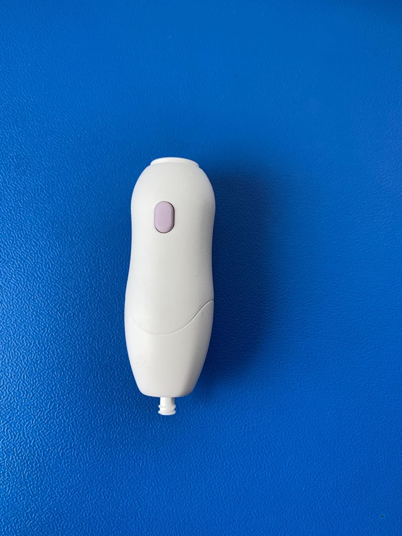
Click to zoom
Application Details
- Equipment Class
- DSC - Part 15 Security/Remote Control Transmitter
- Date of Grant
- May 17, 2023
- Application Purpose
- Original Equipment
- Date of Application
- May 17, 2023
- Equipment Note
- NTrainer 2.0
- Frequency Range
- 915.00000000 - 915.00000000
- Company
- Innara Health, Inc.
- Country
- United States
Documents & Files
Document Text
Text extracted from the exhibit documents filed with the FCC. Open a document above to read the original.
Users Manual
1 IN-P000 REV 3 NTrainer System 2.0 ® Instructions for Use IN-5000 IN-5001 IN-5002 IN-5003 Engenious Design CO-23-27 Released by E. O'Toole on 16-May-2023 2 IN-P000 REV 3 Table of Contents 1. Section 1: Overview ............................................................................................. 5 1.1. About This Manual .................................................................................................................................................. 5 1.2. Introduction ............................................................................................................................................................ 5 1.2.1. Indications for Use .......................................................................................................................................... 5 1.2.2. Intended Patient Population ........................................................................................................................... 5 1.2.3. Product Description ........................................................................................................................................ 5 1.2.4. Unpacking........................................................................................................................................................ 7 1.2.5. Specifications .................................................................................................................................................. 9 1.3. Warnings ............................................................................................................................................................... 10 1.4. Precautions ........................................................................................................................................................... 11 1.5. Notes ..................................................................................................................................................................... 14 2. Section 2: Operation .......................................................................................... 15 2.1. Device Parts ........................................................................................................................................................... 15 2.2. Screens Guide ....................................................................................................................................................... 16 2.2.1. Home Screen ................................................................................................................................................. 16 2.3. Getting Started ...................................................................................................................................................... 17 2.3.1. Power On the System .................................................................................................................................... 17 2.3.2. User Log In..................................................................................................................................................... 17 2.3.3. Pair the Handpiece ........................................................................................................................................ 18 2.3.4. Set Up System Users ..................................................................................................................................... 19 2.3.5. Set Date and Time ......................................................................................................................................... 20 2.3.6. Return to Home Screen ................................................................................................................................. 20 2.3.7. Adjust Screen Brightness .............................................................................................................................. 20 2.3.8. Adjust Volume ............................................................................................................................................... 21 2.3.9. Adjust Screen Tilt .......................................................................................................................................... 21 2.4. User Access Guide ................................................................................................................................................. 22 2.4.1. Feature Access Breakdown ........................................................................................................................... 22 2.5. Patient Files ........................................................................................................................................................... 23 2.5.1. Create a New Patient File .............................................................................................................................. 23 2.5.2. Open an Existing Patient File ........................................................................................................................ 24 2.5.3. Edit Patient File ............................................................................................................................................. 24 Engenious Design CO-23-27 Released by E. O'Toole on 16-May-2023 3 IN-P000 REV 3 2.5.4. Switch Patient Files ....................................................................................................................................... 25 2.5.5. Mark Patient as Inactive................................................................................................................................ 25 2.6. Set Up the Handpiece for Use ............................................................................................................................... 25 2.7. Supporting the Infant Before, During and After an Assessment or Therapy Session ........…
Text truncated - open the document above for the full version.
Attestation Statements
10900 S Clay Blair Blvd, Suite 900. Olathe, KS. 66061 Date: 05-17-2023 To: Federal Communications Commission Authorization and Evaluation Division 7435 Oakland Mills Road Columbia, MD 21046 USA Ref: Attestation Statements Part 2.911(d)(5)(i) and Part 2.911(d)(5)(ii) Filing Re. KDB 986446 D01 FCC ID: 2A9ATIN-5001 Dear Sir or Madam, Innara Health (“the applicant”) certifies that the equipment for which authorization is sought is not “covered” equipment prohibited from receiving an equipment authorization pursuant to section 2.903 of the FCC rules. We also certify that, as of the date of the filing of the application, the applicant is not identified on the Covered List as an entity producing “covered” equipment. If you have any questions, please contact us. Sincerely, Chris Mathia CEO, Innara Health Contact name: Chris Mathia Company name: Innara Health Address: 10900 S. Clay Blair Blvd, suite 900, Olathe, KS. 66061 E-mail: [email protected] Tel: 913-742-4459 10900 S Clay Blair Blvd, Suite 900 Olathe, KS. 66061
Attestation Statements
10900 S Clay Blair Blvd, Suite 900. Olathe, KS. 66061 To: Federal Communications Commission Authorization and Evaluation Division 7435 Oakland Mills Road Columbia, MD 21046 USA Date: 05/17/2023 Ref: Attestation Statements Part 2.911(d)(7) Filing FCC ID: 2A9ATIN-5001 Innara Health (“the applicant”) certifies that, as of the date of the filing of the application, Innara Health is our designated U.S. agent for service of process for the above referenced FCC ID. Innara Health accepts to maintain an agent for no less than one year after the grantee has terminated all marketing and importation or the conclusion of any Commission-related proceeding involving the equipment. Innara Health accepts, as of the date of the filing of the application, the obligation of the designated U.S. agent for service of process for the above referenced FCC ID. Designated U.S. Agent Information: Name: Innara Health Address: 10900 S. Clay Blair Blvd, Olathe, KS 66061 Contact Person: Chris Mathia Tel.: 913-742-4459 Email: [email protected] FRN: 0033068834 Sincerely, Chris Mathia CEO 10900 S Clay Blair Blvd, Suite 900 Olathe, KS. 66061
Cover Letter(s)
10900 S Clay Blair Blvd, Suite 900. Olathe, KS. 66061 Date 05/17/2023 Federal Communications Commission Equipment Authorization Branch 7435 Oakland Mills Road Columbia, MD 21046 Confidentiality Request FCC ID: 2A9ATIN-5001 Pursuant to Sections 0.457(d)(1)(ii) and 0.459 of the Commission’s Rules, Innara Health hereby requests permanent confidential treatment of information accompanying this application as outlined below: Schematics Block Diagrams Theory of Operation The above materials contain trade secrets and proprietary information not customarily released to the public. The public disclosure of these matters might be harmful to the Applicant and provide unjustified benefits to its competitors. The Applicant understands that pursuant to Rule 0.457(d)(1)(ii), disclosure of this Application and all accompanying materials will not be made before the date of the Grant for this Application. Yours sincerely, Chris Mathia CEO, Innara Health 10900 S Clay Blair Blvd, Suite 900 Olathe, KS. 66061
External Photos
Figure 1: View 1 Figure 2: View 2 Figure 3: View 3 Figure 4: View 4
ID Label/Location Info
INTERPRET DIM AND TOL PER ASME Y14.5-2009 THIRD ANGLE PROJECTION TOLERANCES .XX ±0.13 .X ±0.25 ANG ±1° UNLESS OTHERWISE SPECIFIED DIM ARE IN MILLIMETERS 9. 9. 9. ASSEMBLED VIEW 15. NOTES: UNLESS OTHERWISE SPECIFIED NO COMPONENTS MAY BE SUBSTITUTED WITHOUT PRIOR WRITTEN APPROVAL FROM ENGENIOUS.1. ASSEMBLE PER BOM DEFINED IN ENGENIOUS DOCUMENT IN-0010.2. AID ASSEMBLY PER INSTRUCTIONS DEFINED IN ENGENIOUS DOCUMENT IN-0035.3. NOTED OR ENCIRCLED ITEMS SHALL BE INSPECTED.4. TORQUE FASTENERS PER TABLE AA.5. TUBING SHALL BE FREE OF ANY KINKS AFTER INSTALLATION.6. SURFACES SHALL BE FREE OF ALL OILS AND/OR DEBRIS PRIOR TO APPLICATION OF ANY SEALS.7. APPLY PRESSURE PER MANUFACTURER RECOMMENDATIONS ACROSS ENTIRE SURFACE TO ENSURE8. COMPLETE AND EVEN BONDING. VERIFY THE FOLLOWING AFTER ASSEMBLY:9. A CLICK IS HEARD AND FELT WHEN COMPRESSING ITEM 4.• ITEM 9 IS CENTERED WITHIN ENCLOSURE AND DOES NOT SPIN WHEN TWISTED BY HAND.• REVEAL GAP IS EVEN.• VERIFY THE HEX PATTERN RESTS WITHIN THE POCKET OF ITEM 1. VERIFY NO AIR GAP AFTER ITEM 6 INSTALL.10. QTY DEFINES LENGTH HELD TO 2.11. COLORS SHOWN ARE NOT TRUE PART OR MATERIAL COLOR.12. POSITION VIA SILKSCREEN ON PCB.13. ESD SENSITIVE COMPONENT. ESD PRECAUTIONS SHOULD BE TAKEN.14. PRIOR TO ASSEMBLY, IN-1050 SHALL BE MARKED WITH "FCC ID: 2A9ATIN-5001" AND SEQUENTIALLY15. SERIALIZED BY LASER. STARTING AND ENDING SERIAL NUMBER TO SPECIFIED IN EACH P.O TO THE ENGRAVING COMPANY. SERIAL NUMBER TO BE ALIGNED AND CENTERED AND INDICATED IN THE FORMAT OF "H-YY-XXX" WITH "YY" BEING THE LAST TWO DIGITS OF THE YEAR AND "XXX" BEING THE SEQUENTIAL NUMBERS INDICATED ON THE P.O.. DURING ASSEMBLY ENSURE LASER ENGRAVED SERIAL NUMBER ON IN-1050 MATCHES SOFTWARE SERIAL16. NUMBER PROGRAMED INTO IN-E001. 4. 11. 5. 4 REVISIONS ZONEREV.DESCRIPTIONDATEECO N/A2P2 INITIAL RELEASE8/2/2022CO-22-21 A8, B1, 2-B1, 2-B43HANDPIECE SERIAL NUMBER MARKING NOTES12/16/2022CO-22-66 A54UPDATE NOTE 15 TO INCLUDE FCC ID5/17/2023 ITEM NO.PART NUMBERDESCRIPTIONQTY. 1IN-1051HANDPIECE ENCLOSURE BOTTOM1 2IN-1050HANDPIECE ENCLOSURE TOP1 3IN-E001HANDPIECE PCB ASSEMBLY1 4IN-1054HANDPIECE FLEXIBLE BUTTON1 5IN-2040PVC TUBING, 1/16" ID, 1/8" OD, 80A DUROMETER87mm 6IN-2015PANEL MOUNT NUT1 7IN-2014PANEL MOUNT LUER LOCK1 8IN-2045 THREAD-FORMING SCREWS4 9IN-20431/8" COUPLING TO 1/16" BARB1 10IN-2044X-PROFILE O-RING1 11IN-1057HANDPIECE PCB FOAM4 12IN-1055HANDPIECE SEAL1 13IN-2064LOW STRENGTH THREADLOCKERAR TABLE AA ITEMPART NUMBERTORQUETOLERANCE 6IN-2015SNUG-TIGHT - 8IN-20451.0 in-lbs ± 10% CONFIDENTIAL NOT TO SCALE TITLE SIZE B 3 DWG NO SHEET 1 of 2 REV IN-4002 Handpiece Assembly AA BB CC DD 8 8 7 7 6 6 5 5 4 4 3 3 2 2 1 1 NOT RELEASED 2 4 12 TOP LEVEL ASSEMBLY: FRONT ENCLOSURE 7. 11 7. 8. 7. 8.13. 3 7.14. 15. 16. 6 9 10 TOP LEVEL ASSEMBLY: BOTTOM ENCLOSURE 5 6. 713 10. 1 5. 8888 TOP LEVEL ASSEMBLY: BOTTOM ENCLOSURE INSTALLATION 5. 15. 16. CONFIDENTIAL NOT TO SCALE TITLE SIZE B 3 DWG NO SHEET 2 of 2 REV IN-4002 Handpiece Assembly AA BB CC DD 8 8 7 7 6 6 5 5 4 4 3 3 2 2 1 1
Internal Photos
Figure 1: Front View Figure 2: Back View
RF Exposure Info
TÜV SÜD America 5610 West Sligh Ave., Suite 100 Tampa, FL 33634 Phone: 813-284-2715 www.tuv-sud-america.com TÜV SÜD Certification Exhibit FCC ID: 2A9ATIN-5001 FCC Rule Part: 47 CFR Part 2.1093 TÜV SÜD Project Number: 72183115 Manufacturer: Innara Health Inc. Model: IN-5001, Rev 1 RF Exposure Model(s): IN-5001, Rev 1FCC ID: 2A9ATIN-5001 Project: 72183115 TÜV SÜD America Inc. Page 2 General Information: Applicant: InnaraHealth Inc. Environment: General Population/Uncontrolled Exposure Exposure Conditions: Portable Technical Information: Minimum Test Separation Distance: 5 mm Highest Operating Frequency: 915 MHz Antenna Type: Chip Antenna Gain: 0.5 dBi Maximum Transmitter Conducted Power: -7.02 dBm, 0.19860949 mW Maximum Transmitter EIRP: -6.52 dBm, 0.22284351 mW *Maximum Transmitter conducted power derived from radiated field strength measurement and corrected for antenna gain. Justification for SAR Test Exclusion: Standalone SAR Test Exclusion: Per KDB 447498 D01 General RF Exposure Guidance v05r02, the standalone 1-g and 10-g SAR test exclusion thresholds for 100 MHz to 6 GHz at test separation distances ≤ 50 mm are determined by: [(max. power of channel, including tune-up tolerance, mW)/(min. test separation distance, mm)] · [√f(GHz)] ≤ 3.0 for 1-g SAR and ≤ 7.5 for 10-g extremity SAR = (0.19860949 / 5)*( √0.91) = 0.03800 0.03800< 3.0 Standalone SAR test exclusion is applied.
Test Report
■ Bluetooth ■ 802.11 ■ ZigBee ■ Wireless PCMCIA Cards ■ Telemetry ■ Data Collection ■ Industrial Process Monitoring ■ Compact Wireless Products ■ External Antenna Elimination APPLICATIONS The exciting ANT-***-CHP family isamong the world’s smallest high-performance chip antennas. They areideal for embedding in wireless productsincluding Bluetooth, 802.11, Home RF,ZigBee and other popular standards.These tiny antennas use advanced LowTemperature Co-fired Ceramic (LTCC)technology and proprietary elements toachieve superior size and performancecharacteristics. The entire family iscompatible with hand- and reflow-assembly. Excellent electricalspecifications, stability, and outstandingcost-effectiveness make CHP Seriesantennas the logical choice for a widevariety of applications. ANT-2.4-CHP-xANT-868-CHP-xANT-916-CHP-x DESCRIPTION ULTRA COMPACT CHIP ANTENNA DATA GUIDE ■ Incredibly compact SMD package ■ Superior LTCC technology ■ 50 Ω characteristic impedance ■ Low loss ■ Wide bandwidth ■ Favorable linear polarization ■ > Unity gain ■ No external matching required ■ Highly stable over temperature & time ■ Hand- and reflow-assembly compatible ■ RoHS compliant ■ Cost-effective Revised 11/30/11 PHYSICAL DIMENSIONS 2.45GHz 2.4 xxx 868MHz 0.63” (16.0) 0.12”(3.0) ACTUAL SIZE 916MHz 0.07”(1.7) 0.09”(2.2) 0.04”(1.0) 0.26”(6.5) 2.45GHz Version 868 / 916MHz Versions FEATURES ORDERING INFORMATION PART # DESCRIPTION ANT-868-CHP-x 868MHz Chip Antenna ANT-916-CHP-x 916MHz Chip Antenna ANT-2.45-CHP-x 2.45GHz Chip Antenna x = “T” for Tape/Reel, “B” for BulkAll parts are RoHS compliant.Standard reel is 3,000pcs. (868/916MHz) 1,500pcs (2.45GHz) Quantities less than reel size are supplied in bulk. Page 3 Page 2 The CHP Series antennas utilize Low Temperature Cofired Ceramic (LTCC)technology to embed the antenna element into a ceramic substrate. Advances inthis technology have resulted in materials that are extremely stable over timeand temperature, producing an antenna that is highly reliable across a widerange of applications. The high-frequency characteristics of this technologyenable exceptional performance in a very small package. The constructiontechniques for LTCC devices lends itself well to favorable pricing in high volume. SPECIFICATIONS 2.4GHz FOOTPRINT PIN CONFIGURATION 2.4 12 0.100" 0.040" 0.260" 868 & 916MHz FOOTPRINT 0.130" 0.040" 0.630" PHYSICAL SPECIFICATIONS 2.45GHz 868MHz 916MHz Dimensions (mm) 6.5(L) x 2.2(W) x 1.0(H) 16.0(L) x 3.0(W) x 1.7(H) 16.0(L) x 3.0(W) x 1.7(H) Operating/Storage Temp -40 ~ +85°C -40 ~ +85°C -40 ~ +85°C Construction LTCC LTCC LTCC ELECTRICAL PERFORMANCE Center Frequency 2.45GHz 868MHz 916MHz Bandwidth 180MHz 10MHz 10MHz Wavelength 1/4-wave 1/4-wave 1/4-wave Pattern Omni-directional Omni-directional Omni-directional Polarization Linear Linear Linear VSWR < 2.0 (Max.) < 2.0 (Max.) < 2.0 (Max.) Maximum Gain + 0.5dBi + 0.5dBi + 0.5dBi Impedance 50 Ω 50 Ω 50 Ω Power Handling 3W (Max.) 3W (Max.) 3W (Max.) Pin Number Pin Description 1 Feed Termination This pin connects to the transmitter or receiver 2 Solder Termination This pin is soldered down for physical support only. There is no electrical connection Proper layout is vital to ensure correct operation and optimum performance.Improper placement of planes, traces, or system components will result in nullsor complete de-tuning. Ideally, the antenna will be mounted on the board in sucha way as to allow an unobstructed field of view. The area underneath theantenna must be free of components, traces, and planes. Components may beplaced to the rear of the antenna in the ground plane counterpoise area. Thefeed trace from the RF stage to the antenna must be a microstrip trace or coaxtransmission line and should be kept as short as practical. The layout of our reference jigs is illustrated on the following pages. While theydemonstrate various aspects of a layout, it is not necessary to replicate themexactly. While your board size and layout may differ, it is important to recognizethat the counterpoise plays an important role in resonance and stability since itacts, in essence, as part of the antenna. After your own layout is complete, theperformance of the antenna in your specific product should be carefully checkedusing tools like a network analyzer. In some cases, the size of the product’s PCB,proximity of the case, or other factors may make a custom version of the antennanecessary. Contact Antenna Factor for more information. 2.4 No ground plane or tracesunder the antennaGround plane on bottomlayer for counterpoise 50-ohm microstrip line No electrical connection.For physical support onlyPCB pads for the CHP LAYOUT CONSIDERATIONSTHEORY OF OPERATION Page 5 Page 4 Dielectric Constant Width/Height (W/d) Effective Dielectric Constant Characteristic Impedance 4.80 1.8 3.59 50.0 4.00 2.0 3.07 51.0 2.55 3.0 2.12 48.0 Trace Board Ground plane A transmission line is a medium whereby RF energy is transferred from oneplace to another with minimal loss. This is a critical factor, especially in high-frequency products, because the trace leading to the antenna can effectivelycontribute to the length of the antenna, changing its resonant bandwidth. In orderto minimize loss and detuning, some form of transmission line between theantenna and the RF stage should be used, unless the antenna can be placedvery close (<1/8in.) to the RF stage. One common form of transmission line is acoax cable, another is the microstrip. This term refers to a PCB trace runningover a ground plane that is designed to serve as a transmission line between theRF stage and the antenna. The width is based on the desired characteristicimpedance of the line, the thickness of the PCB, and the dielectric constant ofthe board material. For standard 0.062in-thick FR-4 board material, the tracewidth would be 111 mils. The correct trace width can be calculated for otherwidths and materials using the information below. Handy software for calculatingmicrostrip lines is also available …
Text truncated - open the document above for the full version.
Test Report
TÜV SÜD America Inc 141 14 th Street NW New Brighton, MN 55112 Phone: 651-631-2487 www.tuv-sud-america.com TÜV SÜD SIGNATURE NAME JOB TITLE RESPONSIBLE FOR ISSUE DATE Sean SellergrenSr. EMC EngineerAuthorized Signatory08 November 2022 Signatures in this approval box have checked this document in line with the requirements of TÜV SÜD America, Inc. document control rules. FCC Accreditation Designation Number US1148 New Brighton, MN Test Laboratory Innovation, Science, and Economic Development Canada Accreditation Site Number 4512A New Brighton, MN Test Laboratory EXECUTIVE SUMMARY A sample of this product was tested and found to be compliant with the standards listed above and the tests shown in Table 1.3.1 of this report. A2LA Cert. No. 2955.11 DISCLAIMER AND COPYRIGHT This non-binding report has been prepared by TÜV SÜD America with all reasonable skill and care. The document is confidential to the potential Client and TÜV SÜD America. No part of this document may be reproduced without the prior written approval of TÜV SÜD America. © TÜV SÜD. ACCREDITATION Our A2LA Accreditation does not cover opinions and interpretations and any expressed are outside the scope of our A2LA Accreditation. Report on the Testing of the Innara Health Inc. NTRAINER SYSTEM 2.0 FCC ID: 2A9ATIN-5001 In accordance with: FCC 47 CFR Part 15.231 Prepared for: Innara Health Inc. 10900 S Clay Blair Blvd Olathe, Kansas 66061 USA COMMERCIAL-IN-CONFIDENCE Document Number: NC72183115.2 | Issue: 2 Document Number: NC72183115.2 | Issue: 2 COMMERCIAL-IN-CONFIDENCE Page 2 of 32 Contents 1Report Summary .........................................................................................................................3 1.1Report Modification Record ...........................................................................................................3 1.2Introduction ....................................................................................................................................3 1.3Scope of Testing ...........................................................................................................................4 1.4Summary of Results ......................................................................................................................4 1.5Product Information .......................................................................................................................6 1.6Deviations from the Standard ........................................................................................................7 1.7EUT Modification Record ..............................................................................................................7 1.8Test Location .................................................................................................................................7 2Test Details ..................................................................................................................................8 2.1Antenna Requirements..................................................................................................................8 2.2Deactivation Period .......................................................................................................................9 2.3Pulse Characteristics / Duty Cycle ............................................................................................. 12 2.4Radiated Fundamental Field Strength ....................................................................................... 16 2.5Radiated Spurious Field Strength .............................................................................................. 20 2.6Occupied Bandwidth .................................................................................................................. 25 2.7Frequency Stability ..................................................................................................................... 28 3Diagram of Test Setups ........................................................................................................... 29 4Accreditation, Disclaimers and Copyright............................................................................. 32 Document Number: NC72183115.2 | Issue: 2 COMMERCIAL-IN-CONFIDENCE Page 3 of 32 1 Report Summary 1.1 Report Modification Record Alterations and additions to this report will be issued to the holders of each copy in the form of a complete document. Table 1.1-1 – Modification Record Issue Description of Change Date of Issue 1 First Issue 08 November 2022 2 - Added peak limit and margin in table 2.4-1 for Radiated Fundamental Field Strength - Added peak limit to Figure 2-6 for 1-18GHz Radiated Spurious Field Strength - Added peak level, peak limit & peak margin columns to Table 2.5-2 for 1-18GHz Radiated Spurious Field Strength - Changed all references of antenna type from PIFA to chip. 18 May 2023 1.2 Introduction Applicant Innara Health Inc. Manufacturer Innara Health Inc. Applicant’s Email Address [email protected] Model Number(s) NTRAINER SYSTEM 2.0 Serial Number(s) Handpiece: H-P2-002 Hardware Version(s) Handpiece: IN-5001, Rev 1 Number of Samples Tested 1 Test Specification/Issue/Date FCC 47 CFR Part 15.231 Order Number 72183115 Date of Receipt of EUT 26 September 2022 Start of Test 06 October 2022 Finish of Test 07 October 2022 Related Document(s) ANSI C63.10 2013 Document Number: NC72183115.2 | Issue: 2 COMMERCIAL-IN-CONFIDENCE Page 4 of 32 1.3 Scope of Testing To perform certification testing to confirm that the wireless device(s) meet the requirements of the applicable standards and guidance documents. 1.4 Summary of Results A summary of the tests carried out in accordance with the specifications shown below. Table 1.4-1 – Summary of Results Report Section Specification Clause Test Description Accrediation Base Standard 2.1 15.203 Antenna Requirements A2LA FCC Part 15.203 2.2 15.231(a)(1), (2) Deactivation Period A2LA ANSI C63.10…
Text truncated - open the document above for the full version.
Test Setup Photos
SIGNATURE NAME JOB TITLE RESPONSIBLE FOR ISSUE DATE Sean SellergrenSr. EMC EngineerAuthorized Signatory08 November 2022 Signatures in this approval box have checked this document in line with the requirements of TÜV SÜD America, Inc. document control rules. FCC Accreditation Designation Number US1148 New Brighton, MN Test Laboratory Innovation, Science, and Economic Development Canada Accreditation Site Number 4512A New Brighton, MN Test Laboratory Certification Exhibit Test Photos Innara Health Inc. NTRAINER SYSTEM 2.0 FCC ID: 2A9ATIN-5001 Prepared for: Innara Health Inc. 10900 S Clay Blair Blvd Olathe, Kansas 66061 USA COMMERCIAL-IN-CONFIDENCE Document Number: NC72183115.4 | Issue: 1 TÜV SÜD America Inc 141 14 th Street NW New Brighton, MN 55112 Phone: 651-631-2487 www.tuv-sud-america.com Document Number: NC72183115.4 | Issue: 1 COMMERCIAL-IN-CONFIDENCE Page 2 of 6 Contents 1.1EUT Photo .....................................................................................................................................3 1.2Conducted Emissions....................................................................................................................4 1.3Radiated Emissions.......................................................................................................................5 1.4Restricted Band-edge photos ....................................................... Error! Bookmark not defined. TÜV SÜD America Inc 141 14 th Street NW New Brighton, MN 55112 Phone: 651-631-2487 www.tuv-sud-america.com Document Number: NC72183115.4 | Issue: 1 COMMERCIAL-IN-CONFIDENCE Page 3 of 6 1.1 EUT Photo Photo 1.1-1 – EUT Front View Photo is of the transmitter outside of the plastic enclosure. TÜV SÜD America Inc 141 14 th Street NW New Brighton, MN 55112 Phone: 651-631-2487 www.tuv-sud-america.com Document Number: NC72183115.4 | Issue: 1 COMMERCIAL-IN-CONFIDENCE Page 4 of 6 1.2 Conducted Emissions Photo 1.2-1 – Conducted Test Setup TÜV SÜD America Inc 141 14 th Street NW New Brighton, MN 55112 Phone: 651-631-2487 www.tuv-sud-america.com Document Number: NC72183115.4 | Issue: 1 COMMERCIAL-IN-CONFIDENCE Page 5 of 6 1.3 Radiated Emissions Photo 1.3-1 – RE Spurious Emissions 30-1000 MHz TÜV SÜD America Inc 141 14 th Street NW New Brighton, MN 55112 Phone: 651-631-2487 www.tuv-sud-america.com Document Number: NC72183115.4 | Issue: 1 COMMERCIAL-IN-CONFIDENCE Page 6 of 6 Photo 1.3-2 – RE Spurious Emissions 1-18 GHz
Contact Information
Applicant
Cassie Riesgo(Quality Assurance Manager)
Test Firm
TUV SUD America Inc.William Elliott
Technical Specifications
| # | Rule Parts | Frequency Range | Power Output |
|---|---|---|---|
| 1 | 15.231 | 915 MHz - 915 MHz | - |