2A9DS-CBBLK-E22Educational Toys
COBO Co., Ltd.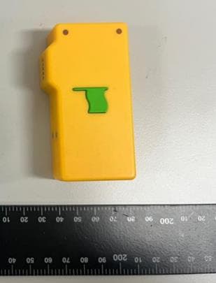
Click to zoom
Application Details
- Equipment Class
- DTS - Digital Transmission System
- Date of Grant
- Jan 10, 2023
- Application Purpose
- Original Equipment
- Date of Application
- Jan 10, 2023
- Equipment Note
- Educational Toys
- Frequency Range
- 2402.00000000 - 2480.00000000
- Company
- COBO Co., Ltd.
- Country
- South Korea
Documents & Files
Document Text
Text extracted from the exhibit documents filed with the FCC. Open a document above to read the original.
Users Manual
User Manual Register your product and get support at www.coboblocks.com Battery safety precaution •Danger of explosion if a battery is incorrectly replaced. Replace only with the same or equivalent type. •A battery (battery pack or battery installed) shall not be exposed to excessive heat such as sunshine, fire or the like. •A battery in extreme high or low temperatures during use, storage or transportation, and low air pressure at high altitude can pose safety hazards. •Do not replace a battery with an incorrect type that can defeat a safeguard(for example, some lithium battery types). •Disposing a battery into fire or a hot oven, mechanically crushing or cutting a battery can result in an explosion. •Leaving a battery in an extremely high temperature surrounding, or an extremely low air pressure environment may result in an explosion or leakage of flammable liquid or gas. * Warring •Never remove the casing of this device. •Never lubricate any part of this device. •Place this device on a flat, hard and stable surface. •Never place the device on other electrical equipment. •Only use this device indoors, keep this device away from water, moisture and liquid-filled objects. •Keep this devices away form direct sunlight, naked flames or heat. •Risk of explosion if a battery is replaced by an incorrect type. Contents 1 Important Safety 2 Your CoboBlocks; Scratch e-Blocks for coding Introduction What’s in the box Overview of the Coding Car Overview of the Event Block 3 Get started Charge the Event Block and Coding Car Turn on/off Pairing for Event Block with Coding Car 4 Product information 5 Notice Compliance Care of the environment FCC Statement 1 Important Safety Important safety instructions •Make sure that the power supply voltage corresponds to the voltage of the unit. (There is a rating label on the back of the unit). •The device shall not be exposed to dripping of splashing. •Do not place any source of danger on the device (e.g. liquid filled objects, lit candles). •Make sure that there is enough free space around the device for ventilation. •Please use the device safely in an environment with temperature between 0° and 45° •Only use attachments and accessories specified by the manufacturer. EN 1 2 Your CoboBlocks; Scratch e-Blocks for coding Congratulations on your purchase, and welcome to CoboBlocks! To Fully benefit from the support that CoboBlocksoffers, register your product at www.coboblocks.com Introduction With this device , you can enjoy unplug coding. What’s in the box Check and identify the contents of your package; •Coding Car x 1pc •Event Block x 1pc •Motion Block x 4pcs •Control Block x 3pcs •Sound Block x 1pc •Dancing Block x 1pc •LED Block x 1pc •Line Tracing Block x 1pc •Self Driving Block x 1pc •Random Block x 1pc •USB Charging Cable x 1pc Overview of the Coding Car IR SensorHead Light Turn Signal Wheel Reversing Light (Charging Indicator) C-Type Charging Port Power Switch Speaker Bottom Light IR Sensor Overview of the Event Block Power Switch (Reset Key) C-Type Charging Port Event Indicator Charging Indicator Event Button (Pairing Button) EN 2 3 Get started Always follow the instructions in this chapter in sequence. Charge the Event Block and Coding Car The Event Block and Coding Car is Powered by a Built-in rechargeable battery. *Note •Fully charge the built-in battery before using. •When the Event Block and Coding Car is Blue lamp turn on and the battery is low. Connect the TYPE-C USB socket on the device to an outlet / Charger (5V 1A) by using the provided USB Cable. * Caution •Risk of device damage! Make sure that the power supply voltage corresponds to the voltage of the unit. •Risk of electric shock! When unplug the USB cable, always pull the plug from the socket, Never pull the cable. •Use only a USB cable specified by the manufacture of sold with this unit When the device is being charged, the LED indicator is solid blue When the device is fully charged, the LED indicator is off Turn on/off Press to “Power Switch” 3s turn the device on Turn the device off, press again to “Power Switch”. Note The device will turn off automatically after 10 minutes without using. Pairing for Event Block with Coding Car Event Button (Pairing Button) Press to “Event Button / Pairing Button” pairing will be done automatically. EN 3 4 Product information * Note Product information is subject to change without prior notice. General Information ItemCoding CarEvent Block Power Supply5V DC 1A5V DC 1A Built-in Lithium Battery 3.7V, 1200mAh3.7V, 750mAh Dimensions (WxHxD) 87x90x52mm85x45x20mm Weight (unit)162g50g Bluetooth Bluetooth version5.0 Frequency range2402 –2480 MHz Bluetooth rangeApprox. 10m 5 Notice Any changes or modifications made to this device that are not expressly approved by COBOBLOCKS INC. may void the user’s authority to operate the product. Compliance Hereby, COBOBLOCKS INC. declares that this product is in compliance with the essential requirements and other relevant provisions of Directive 2014/53/EU. You can find the Declaration of Conformity on www.coboblocks.com Care of the environment Disposal of your old product and battery Your product is designed and manufactured with high quality materials and components, which can be recycled and reused. This symbol on a product means that the product is covered by European Directive 2012/19/EU This symbol means that the product contains batteries covered by European Directive 2013/56/EU which cannot be disposed of with normal household waste. Inform yourself about the local separate collection system for electrical and electronic product and batteries. Follow local rules and never dispose of the product and batteries with normal household waste. Correct disposal of old products and batteries helps prevent negative consequences of the environment and human health. EN 4 FCC Statement This device complies with Part 15 of the FCC Rules, Operation is subject to the following two conditions; (1) This device may not cause harmful i…
Text truncated - open the document above for the full version.
Cover Letter(s)
Date: 04/17/2018 VCB_F-01: Operating Procedures Form – FCC Authorization v02 Page 1 of 1 COBO Co.,Ltd. Federal Communications Commission Authorization and Evaluation Division 1435 Oakland Mills Road Columbia, MD 21046 Date: SUBJECT: FCC Application for (FCC ID: 2A9DS-CBBLK-E22) To Whom It May Concern: We, the undersigned, hereby authorize Seong-Hun,Jeong in ICR Co.,Ltd on our behalf, to apply to the Federal Communications Commission on our equipment. Any and all acts carried out by ICR Co.,Ltd on our behalf shall have the same effect as acts of our own. This is to advise that we are in full compliance with the Anti- Drug Abuse Act. We, the applicant, are not subject to a denial of federal benefits pursuant to Section 5301 of the Anti-Drug Act of 1988, 21 USC853a, and no party to the application is subject to a denial of federal benefits pursuant to that section. Sincerely, (Must be signed by the person that is listed on the FCC Website) Client’s signature: Client’s name & title: Seokiu Chun / Engineer Contact information / address: COBO Co.,Ltd.
Cover Letter(s)
Date: 04/17/2018 VCB_F-01: Operating Procedures Form – FCC Confidentiality v03 Page 1 of 1 COBO Co.,Ltd. Federal Communications Commission Authorization and Evaluation Division Confidentiality Request regarding application for certification of FCC ID: 2A9DS-CBBLK-E22 Pursuant to Sections 0.457 and 0.459 of the Commission’s Rules, we hereby request confidential treatment of information accompanying this application as outlined below: Type of Confidentiality Requested Exhibit Type ☐Short Term ☒Permanent Block Diagrams ☒Short Term External Photos ☒Short Term ☐Permanent* Internal Photos ☐Short Term ☒Permanent Operation Description ☐Short Term ☒Permanent Parts List/BOM ☐Short Term ☒Permanent Schematics ☒Short Term Test Setup Photos ☒Short Term ☐Permanent* User manual *Requires further justification before permanent confidentiality will be allowed. The above materials contain trade secrets and proprietary information not customarily released to the public. The public disclosure of these materials may be harmful to the applicant and provide unjustified benefits to its competitors. Permanent Confidentiality: The applicant requests the exhibits listed above as permanently confidential be withheld from public review due to materials that contain trade secrets and proprietary information not customarily released to the public. Short-Term Confidentiality: Pursuant to DA04-1705 June 15, 2004 of the Commission’s public notice, we also request temporary confidential treatment of information accompanying this application as outlined below for an initial period of 180 (ie- “45”, “90” or “180”) days. Sincerely, Client’s signature: Client’s name & title: Seokiu Chun / Engineer Contact information / address: [email protected]
External Photos
Front Rear SIDE 1 SIDE 2 SIDE 3 SIDE 4
Internal Photos
Internal of sample Antenna Main Board (front) Main Board (rear)
RF Exposure Info
페이지(page) : ( 2 )/( 총(Total) 7 ) ICRT-QPA-17-03 Rev.2 Report No. ICRT-TR-E230009-0A Contents 1. Applicant & Manufacturer & Test Laboratory Information .................................................................................. 4 1.1 Applicant information ........................................................................................................................................ 4 1.2 Manufacturer Information ................................................................................................................................. 4 1.3 Test Laboratory Information ............................................................................................................................ 4 2. Equipment under Test(EUT) Information ................................................................................................................. 5 2.1 General Information ........................................................................................................................................... 5 2.2 Additional Information ...................................................................................................................................... 5 2.3 Mode of operation during the test .................................................................................................................. 5 2.4 Modifications of EUT ......................................................................................................................................... 5 3. Maximum Permissible Exposure ............................................................................................................................... 6 3.1 RF Exposure calculation .................................................................................................................................. 6 3.2 Result ..................................................................................................................................................................... 7 페이지(page) : ( 3 )/( 총(Total) 7 ) ICRT-QPA-17-03 Rev.2 Report No. ICRT-TR-E230009-0A Revision History Issued Report No. Issued Date Revisions Effect Section ICRT-TR-E230009-0A 2022.01.02 Initial Issue All 페이지(page) : ( 4 )/( 총(Total) 7 ) ICRT-QPA-17-03 Rev.2 Report No. ICRT-TR-E230009-0A 1. Applicant & Manufacturer & Test Laboratory Information 1.1 Applicant information Applicant COBO Co.,Ltd. Address 204-1ho, 417, Samseong-ro, Gangnam-gu, Seoul, Korea Contact Person Seokiu Chun Telephone No. 82-10-9018-3047 Fax No. - E-mail [email protected] 1.2 Manufacturer Information Manufacturer COBO Co.,Ltd. Address 204-1ho, 417, Samseong-ro, Gangnam-gu, Seoul, Korea 1.3 Test Laboratory Information Conducted tests were performed at Laboratory ICR Co., Ltd. Address 112, Hwanggeum 3-ro 7beon-gil, Hagun-ri, Yangchon-eup, Gimpo-si, Gyeonggi- do, Korea Telephone No. +82-2-6351-9002 Fax No. +82-2-6351-9007 RRA No. KR0165 KOLAS No. KT652 페이지(page) : ( 5 )/( 총(Total) 7 ) ICRT-QPA-17-03 Rev.2 Report No. ICRT-TR-E230009-0A 2. Equipment under Test(EUT) Information 2.1 General Information Product Name COBOBLOCKS Brand Name - Model Name CBBLK-E22 Additional Model Name - FCC ID 2A9DS-CBBLK-E22 Hardware Version 1.0 2.2 Additional Information Equipment Class DTS - Digital Transmission System Device Type Stand-alone Operating Frequency 2 402 ㎒ ~ 2 480 ㎒ RF Output Power -31.26 ㏈m Number of Channel 40 Modulation Type GFSK Antenna Type Chip Antenna Antenna Gain 2.05 ㏈i Antenna Operating Mode Single Antenna Equipment with only one antenna 2.3 Mode of operation during the test - The EUT is continuous transmission mode during the test with set at Low Channel, Middle Channel, and High Channel. To get a maximum radiated emission levels from the EUT, the EUT was moved throughout the XY, YZ, XZ planes. 2.4 Modifications of EUT - None 페이지(page) : ( 6 )/( 총(Total) 7 ) ICRT-QPA-17-03 Rev.2 Report No. ICRT-TR-E230009-0A 3. RF Exposure 3.1 RF Exposure calculation. Kind of EUT RECEIVER Operating Frequency Band □ WLAN(802.11b/g/n(HT20)): 2 412 ㎒ ~ 2 462 ㎒ □ WLAN(802.11n(HT40)): 2 422 ㎒ ~ 2 452 ㎒ □ WLAN: 5 180 ㎒ ~ 5 320 ㎒ / 5 500 ㎒ ~ 5 700 ㎒ □ WLAN: 5 745 ㎒ ~ 5 825 ㎒ ■ Bluetooth: 2 402 ㎒ ~ 2 480 ㎒ Max. Output Power ㏈m Exposure Evaluation Applied □ MPE □ SAR ■ N/A 페이지(page) : ( 7 )/( 총(Total) 7 ) ICRT-QPA-17-03 Rev.2 Report No. ICRT-TR-E230009-0A 3.2 Result According to the procedure, KDB 447498 D01, the standalone SAR test exclusion threshold is [(Max. Power of channel, including tune-up tolerance, ㎽) / (Min. test separation distance, ㎜)] x [√f(㎓)] < 7.5 Conclusion: The SAR test exclusion threshold is less than 7.5, so the device meets the RF Exposure Requirement and excluded SAR Test. Operating Mode Frequency (㎒) Target Power W / tolerance Max tune up power Separation distance (㎜) RF exposure Limit (㏈m) (㏈m) (㎽) Bluetooth LE 2 480 -31.26± 0.5 -30.76 0.0008 5.00 0.20 7.5 - END -
Test Report
페이지(page) : ( 2 )/( 총(Total) 34 ) ICRT-QPA-17-03 Rev.2 Report No. ICRT-TR-E230008-0A Contents 1. Applicant & Manufacturer & Test Laboratory Information .................................................................................. 5 1.1 Applicant information ........................................................................................................................................ 5 1.2 Manufacturer Information ................................................................................................................................. 5 1.3 Test Laboratory Information ............................................................................................................................ 5 2. Equipment under Test(EUT) Information ................................................................................................................. 6 2.1 General Information ........................................................................................................................................... 6 2.2 Additional Information ...................................................................................................................................... 6 2.3 Mode of operation during the test .................................................................................................................. 6 2.4 Modifications of EUT ......................................................................................................................................... 6 3. Test Summary ................................................................................................................................................................. 7 3.1 Test standards and results .............................................................................................................................. 7 3.2 Purpose of the test ............................................................................................................................................. 7 3.3 Test Methodology ............................................................................................................................................... 7 3.4 Configuration of Test System ......................................................................................................................... 7 3.5 Antenna requirement ......................................................................................................................................... 8 4. Used equipment on test ............................................................................................................................................... 9 5. 6 ㏈ Bandwidth ............................................................................................................................................................ 10 5.1 Operating environment ................................................................................................................................... 10 5.2 Measurement method ...................................................................................................................................... 10 5.3 Test setup ........................................................................................................................................................... 10 5.4 Test data ............................................................................................................................................................. 11 6. Maximum Conducted Output Power ....................................................................................................................... 13 6.1 Operating environment ................................................................................................................................... 13 6.2 Measurement method ...................................................................................................................................... 13 6.3 Test setup ........................................................................................................................................................... 13 6.4 Test data ............................................................................................................................................................. 14 7. Power Spectral Density .............................................................................................................................................. 16 7.1 Operating environment ................................................................................................................................... 16 7.2 Measurement method ...................................................................................................................................... 16 7.3 Test setup ........................................................................................................................................................... 16 7.4 Test data ............................................................................................................................................................. 17 8. Conducted Spurious Emission ................................................................................................................................ 19 8.1 Operating environment ................................................................................................................................... 19 8.2 Measurement method ...................................................................................................................................... 19 8.3 Test setup ........................................................................................................................................................... 19 8.4 Test data ...............................................................................................................…
Text truncated - open the document above for the full version.
Contact Information
Applicant
Seokiu Chun
Test Firm
ICR Co., Ltd.Sim Sang-Woo
Technical Specifications
| # | Rule Parts | Frequency Range | Power Output |
|---|---|---|---|
| 1 | 15C | 2.40 GHz - 2.48 GHz | 0.70 µW |