2A9FB-BTSElectric Fireplace
CAN-PACIFIC ENTERPRISES LTD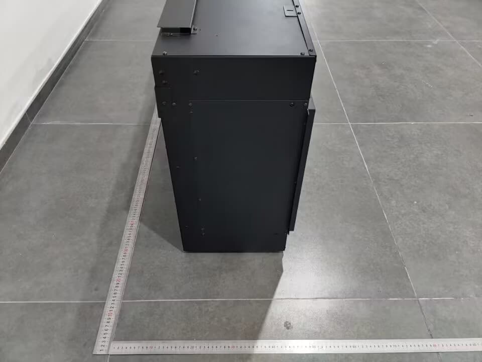
Click to zoom
Application Details
- Equipment Class
- DTS - Digital Transmission System
- Date of Grant
- Jan 07, 2023
- Application Purpose
- Original Equipment
- Date of Application
- Jan 05, 2023
- Equipment Note
- Electric Fireplace
- Frequency Range
- 2412.00000000 - 2462.00000000
- Company
- CAN-PACIFIC ENTERPRISES LTD
- Country
- Canada
Documents & Files
Document Text
Text extracted from the exhibit documents filed with the FCC. Open a document above to read the original.
Users Manual
DYNASTY FIREPLACES Melody Series | Séries Melody 3-sided smart electric fireplace • Foyer électrique intelligent à 3 faces Installation Instructions & Operating Manual Manuel d’Installation & d’Utilisation Models / Modèles DY-BTS35 / DY-BTS40 / DY-BTS60 3231 No. 6 Road, Unit 127, Richmond, BC V6V 1P6 Canada PHONE: +1 877-521-1009 | [email protected] | dynastyfireplaces.com READ CAREFULLY BEFORE ATTEMPTING TO ASSEMBLE, INSTALL, OPERATE, OR MAINTAIN THIS PRODUCT. PROTECT YOURSELF AND OTHERS BY OBSERVING ALL SAFETY INFORMATION. FAILURE TO COMPLY WITH INSTRUCTIONS COULD RESULT IN PERSONAL INJURY AND/OR PROPERTY DAMAGE. LIRE ATTENTIVEMENT AVANT D’ESSAYER D’ASSEMBLER, D’INSTALLER, D’UTILISER, OU D’ENTRETENIR CE PRODUIT. PROTÉGEZ-VOUS ET VOTRE ENTOURAGE EN RESPECTANT LES CONSIGNES DE SÉCURITÉ. LE NON-RESPECT DE CES CONSIGNES POURRAIT CAUSER DES BLESSURES CORPORELLES ET / OU DES DOMMAGES MATÉRIELS. WARNING: To reduce risk of fire, electrical shock, or personal injury, read and understand all instructions, including safety information before plugging in and operating. AVERTISSEMENT: Pour réduire le risque d’incendie, de décharge électrique, ou de blessures corporelles, lisez et assurez-vous de comprendre toutes les instructions, y compris les consignes de sécurité, avant de brancher et d’utiliser cet appareil. © 2022 Dynasty Fireplaces | V 1.0.0 - 2 - For setup guides, full product specs, and warranty information, please visit us at: support.dynastyfireplaces.com Contact us: [email protected] 1-877-521-1009 © 2022 Dynasty Fireplaces | V 1.0.0 - 3 - SAFETY INFORMATION • Read all instructions before using this heater! • This heater is hot when in use. To avoid burns, DO NOT let bare skin touch hot surfaces. If provided, use handles when moving this heater. Keep combustible materials, such as furniture, pillows, bedding, papers, clothes, and curtains at least 3 feet (0.9m) from the front of the heater and keep them away from the sides and rear. • Extreme caution is necessary when any heater is used by or near children or invalids and whenever the heater is left operating and unattended. • DO NOT operate any heater with a damaged cord or plug or after the heater malfunctions, has been dropped or damaged in any manner. Discard heater or return to authorized service facility for examination and/or repair. • DO NOT run power cord under carpeting. DO NOT cover power cord with throw rugs, runners, or similar coverings. DO NOT route power cord under furniture or appliances. Arrange power cord away from traffic area, and where it will not be tripped over. • DO NOT insert or allow foreign objects to enter any ventilation or exhaust opening, as this may cause electric shock or fire, or damage the heater. • To prevent a possible fire, DO NOT block air intakes or exhaust in any manner. Doing so could cause a fire. DO NOT use on soft surfaces, like a bed, where openings may become blocked. • A heater has hot and arcing or sparking parts inside. DO NOT use it in areas where gasoline, paint, or flammable liquids are used or stored. • Use this heater only as described in this manual. Any other use not recommended by the manufacturer may cause fire, electric shock, or injury to persons. • ALWAYS plug heaters directly into a wall outlet/receptacle. NEVER use with an extension cord or relocatable power tap (outlet/power strip). • DO NOT place the heater near a bed because objects such as pillows or blankets can fall off the bed and be ignited by the heater. • NEVER use this heater in bathrooms, laundry rooms, or any other location where the heater could fall into a bathtub or pool, become damp, or come in contact with water. • AVOID FIRE! Regularly inspect all air vents to make sure they are free from dust, lint, or other blockage. Unplug the unit and clean with a vacuum ONLY. DO NOT rinse or get wet. • NEVER hang this unit on a wall directly below an electrical outlet. • NEVER permanently install in a recessed area of the wall. This may result in blocked air flow, overheating, or fire. • ALWAYS secure to wall framing before use. © 2022 Dynasty Fireplaces | V 1.0.0 - 4 - SAFETY INFORMATION • WARNING: REDUCE THE RISK OF FIRE OR ELECTRIC SHOCK---DO NOT USE THIS HEATER WITH ANY SOLID-STATE SPEED CONTROL DEVICES. • This product is not intended to be a primary heat source. It is for supplemental heat only. • INDOOR use only! NEVER use this heater outdoors! Doing so may result in electric shock! • Risk of electric shock! DO NOT OPEN! No user-serviceable parts inside! • NEVER modify this heater. Doing so could result in personal injury or property damage. Modification of this fireplace completely voids all warranties. • ALWAYS turn this heater off before unplugging it from the outlet. • ALWAYS disconnect this unit from the power supply before performing any assembly or cleaning, or before relocating the electric fireplace. • NEVER leave this heater unattended. ALWAYS unplug this heater when not in use. • ALWAYS store this heater in a dry location. NEVER use the fireplace if it has become wet. • ONLY use this heater on a 120V AC 15-Amp circuit. NEVER overload the circuit. If this heater trips the circuit breaker, unplug all other appliances on the same circuit before the next use. Avoid plugging other appliances into the same circuit as this heater. • NEVER plug this heater into an outlet that is old, cracked, or has any loose wires or connections. Plugging this heater into a faulty outlet could result in electric arcing within the outlet that could cause the outlet to overheat or catch fire. • ALWAYS check your heater cord and plug connections with each use! 1. MAKE SURE the plug fits tight in the outlet! Faulty wall outlet connections or loose plugs can cause the outlet to overheat. 2. Heaters draw more current than small appliances. Overheating may occur even if it has not occurred with the use of other appliances. 3. During use check frequently to see if the plug outlet or faceplate is HOT! If the …
Text truncated - open the document above for the full version.
Attestation Statements
CAN-PACIFIC ENTERPRISES LTD Date: 2022-12-30 To: Federal Communications Commission 7435 Oakland Mills Road Columbia, MD FCC ID: 2A9FB-BTS To Whom It May Concern: This letter is to ascertain that CAN-PACIFIC ENTERPRISES LTD EUT : Electric Fireplace Model Name : DY-BTS35, DY-BTS40, DY-BTS60 We will apply for FCC SDOC. If you have any question or concerns, pls. contact us. Sincerely, Client’s signature : Client’s name / title : Jack Zhang /chief inspector Contact information / address: CAN-PACIFIC ENTERPRISES LTD /3231 No. 6 Road, Unit 127 Richmond, BC Canada V6V 1P6
Cover Letter(s)
(CAN-PACIFIC ENTERPRISES LTD) Federal Communications Commission Authorization and Evaluation Division 1435 Oakland Mills Road Columbia, MD 21046 Date: December 30, 2022 SUBJECT: FCC Application for FCC ID: 2A9FB-BTS To Whom It May Concern: We, the undersigned, hereby authorize Tony Wei at EMTEK(NINGBO) CO., LTD. on our behalf, to apply to the Federal Communications Commission on our equipment. Any and all acts carried out by EMTEK(NINGBO) CO., LTD. on our behalf shall have the same effect as acts of our own. This is to advise that we are in full compliance with the Anti- Drug Abuse Act. We, the applicant, are not subject to a denial of federal benefits pursuant to Section 5301 of the Anti-Drug Act of 1988, 21 USC853a, and no party to the application is subject to a denial of federal benefits pursuant to that section. Regards, Jack Zhang /chief inspector CAN-PACIFIC ENTERPRISES LTD
Cover Letter(s)
Difference Statement FCC ID: 2A9FB-BTS The PCB schematic diagram and PCB Layout of the three models are the same. The only difference is that DY-BTS35 and DY-BTS40 have three fan motor, DY-BTS-60 have five fan motor. We choose DY-BTS-60 for RF testing. Jack Zhang /chief inspector CAN-PACIFIC ENTERPRISES LTD DY-BTS35, DY-BTS40, DY-BTS60
Cover Letter(s)
(CAN-PACIFIC ENTERPRISES LTD) Federal Communications Commission Authorization and Evaluation Division Confidentiality Request regarding application for certification of FCC ID: 2A9FB-BTS Pursuant to Sections 0.457 and 0.459 of the Commission’s Rules, we hereby request confidential treatment of information accompanying this application as outlined below: Exhibit Type File Name Block Diagram, Schematics, Operational Description Block Diagram .pdf, Schematics .pdf , Operation Description .pdf The above materials contain trade secrets and proprietary information not customarily released to the public. The public disclosure of these materials may be harmful to the applicant and provide unjustified benefits to its competitors. The applicant understands that pursuant to Section 0.457 of the Rules, disclosure of this application and all accompanying documentation will not be made before the date of the Grant for this application. Pursuant to DA04-1705 June 15, 2004 of the Commission’s public notice, we also request temporary confidential treatment of information accompanying this application as outlined below: Short-term confidentiality requested: 180 days Exhibit Type File Name Internal Photos, Test Setup Photos, Manual Internal Photos .pdf, Test Setup Photos .pdf, User Manual .pdf Sincerely, Jack Zhang /chief inspector CAN-PACIFIC ENTERPRISES LTD
External Photos
External photos: ---The End---
ID Label/Location Info
Label Location
Internal Photos
Internal photos: Antenna ---The End---
RF Exposure Info
FCC ID: 2A9FB-BTS RF EXPOSURE EVALUATION According to FCC 1.1310: The criteria listed in the following table shall be used to evaluate the environment impact of human exposure to radio frequency(RF) Radiation as specified in §1.1307(b) Limits for Maximum Permissible Exposure (MPE) Frequency Range(MHz) Electric Field Strength(V/m) Magnetic Field Strength(A/m) Power Density(mW/cm 2 ) Average Time (A) Limits for Occupational/Control Exposures 300-1500 -- -- F/300 6 1500-100000 -- -- 5 6 (B) Limits for General Population/Uncontrol Exposures 300-1500 -- -- F/1500 6 1500-100000 -- -- 1 30 11.1 Friis transmission formula: Pd= (Pout*G)\ (4*pi*R 2 ) Where Pd= Power density in mW/cm 2 Pout=output power to antenna in mW G= Numeric gain of the antenna relative to isotropic antenna Pi=3.1416 R= distance between observation point and center of the radiator in cm Pd the limit of MPE,1mW/cm 2 . If we know the maximum gain of the antenna and total power input to the antenna, through the calculation, we will know the distance where the MPE limit is reached. mW = 10^( dBm/10) 11.2 Measurement Result Operation Frequency: 2412 MHz-2462 MHz; Antenna gain: 2.50 dBi; R=20cm WIFI Channel Freq. (MHz) modulation Measured power (dBm) Tune-up power (dBm) Max tune-up power (dBm) Antenna Gain Numeric Evaluation result (mW/cm2) Power density Limits (mW/cm2 ) 2412 802.11b 14.85 14±1 15 1.78 0.011187399 1 2437 15.19 15±1 16 1.78 0.014084101 1 2462 15.14 15±1 16 1.78 0.014084101 1 2412 802.11g 11.70 11±1 12 1.78 0.005606982 1 2437 12.16 12±1 13 1.78 0.007058772 1 2462 12.08 12±1 13 1.78 0.007058772 1 2412 802.11n20 11.81 11±1 12 1.78 0.005606982 1 2437 12.04 12±1 13 1.78 0.007058772 1 2462 11.93 11±1 12 1.78 0.005606982 1 *** End of Report ***
Test Report
Report No.EDG2211140170E00501R Page 41 of 58 Ver.1.0 8.5 RADIATED SPURIOUS EMISSION 8.5.1 Applicable Standard According to FCC Part 15.247(d) and 15.209 and KDB 558074 D01 15.247 Meas Guidance v05r02 8.5.2 Conformance Limit According to FCC Part 15.247(d): radiated emissions which fall in the restricted bands, as defined in §15.205(a), must also comply with the radiated emission limits specified in §15.209(a) (see §15.20 5(c)). Acco rding to FCC Part15.205, Restricted band s MHz MHz MHz GHz 0.090-0.110 16.42-16.423 399.9-410 4.5-5.15 10.495-0.505 16.69475-16.69525 608-6145.35-5.46 2.1735-2.1905 16.80425-16.80475 960-12407.25-7.75 4.125-4.128 25.5-25.67 1300-1427 8.025-8.5 4.17725-4.17775 37.5-38.25 1435-1626.5 9.0-9.2 4.20725-4.20775 73-74.61645.5-1646.5 9.3-9.5 6.215-6.218 74.8-75.2 1660-1710 10.6-12.7 6.26775-6.26825 123-1382200-2300 14.47-14.5 8.291-8.294 149.9-150.05 2310-2390 15.35-16.2 8.362-8.366 156.52475-156.52525 2483.5-2500 17.7-21.4 8.37625-8.38675 156.7-156.9 2690-2900 22.01-23.12 8.41425-8.41475 162.0125-167.17 3260-3267 23.6-24.0 12.29-12.293 167.72-173.2 3332-3339 31.2-31.8 12.51975-12.52025 240-2853345.8-3358 36.43-36.5 12.57675-12.57725 322-335.43600-4400 (2) 13.36-13.41 According to FCC Part15.205,the level of any transmitter spurious emission in Restricted bands shall not exceed the level of the emission specified in the following table Restricted Frequency(MHz) Field Strength ( μV/m) Field Strength (dB μV/m) Measurement Distance 0.009-0.490 2400/F(KHz) 20 log (uV/m) 300 0.490-1.705 24000/F(KHz) 20 log (uV/m) 30 1.705-30 30 29.5 30 30-88100 40 3 88-216150 43.5 3 216-960200 46 3 Above 960 500 54 3 8.5.3 Test Configuration Test according to clause 7.2 radio frequency test setup 2 8.5.4 Test Procedure This test is required for any spurious emission that falls in a Restricted Band, as defined in Section 15.205. It must be performed with the highest gain of each type of antenna proposed for use with the EUT. Use the following spectrum analyzer settings: The EUT was placed on a turn table which is 0.8m above ground plane. Maximum procedure was performed on the highest emissions to ensure EUT compliance. Span = wide enough to fully capture the emission being measured RBW = 1 MHz for f 1 GHz(1GHz to 25GHz), 100 kHz for f < 1 GHz(30MHz to 1GHz), 200Hz for f<150KHz(9KHz to 150KHz), 9KHz for f<30MHz(150KHz to 30KHz) VBW RBW Sweep = auto Report No.EDG2211140170E00501R Page 42 of 58 Ver.1.0 Detector function = peak Trace = max hold Follow the guidelines in ANSI C63.10-2013 with respect to maximizing the emission by rotating the EUT, measuring the emission while the EUT is situated in three orthogonal planes (if appropriate), adjusting the measurement antenna height and polarization, etc. A pre-amp and a high pass filter are required for this test, in order to provide the measuring system with sufficient sensitivity. Allow the trace to stabilize. The peak reading of the emission, after being corrected by the antenna factor, cable loss, pre-amp gain, etc., is the peak field strength, which must comply with the limit specified in Section 15.35(b). Submit this data. Now set the VBW to 10 Hz, while maintaining all of the other instrument settings. This peak level, once corrected, must comply with the limit specified in Section 15.209. If the dwell time per channel of the hopping signal is less than 100 ms, then the reading obtained with the 10 Hz VBW may be further adjusted by a “duty cycle correction factor”, derived from 20log(dwell time/100 ms), in an effort to demonstrate compliance with the 15.209 limit. Submit this data. Repeat above procedures until all frequency measured was complete. 8.5.5 Test Results Temperature: 22.5 C Relative Humidity: 45 ATM Pressure: 1011 mbar Spurious Emission below 30MHz(9KHz to 30MHz) Freq. (MHz) Ant.Pol. Emission Level(dBuV/m) Limit 3m(dBuV/m) Over(dB) H/V PK AV PK AV PK AV -- -- -- -- -- -- -- -- Note: the amplitude of spurious emission that is attenuated by more than 20dB below the permissible limit has no need to be reported. Distance extrapolation factor =40log(Specific distance/ test distance)( dB); Limit line=Specific limits(dBuV) + distance extrapolation factor Report No.EDG2211140170E00501R Page 43 of 58 Ver.1.0 Spurious Emission Above 1GHz(1GHz to 25GHz) All modes 2.4G 802.11b/g/n have been tested, and the worst result 802.11b recorded was report as below: Test mode: 802.11 b Frequency: Channel 1: 2412 MHz Freq. (MHz) Reading (dBμV) Corr. (dB) Meas. (dBμV/m) Limit (dBμV/m) Margin (dBμV/m) Det. Pol. Verdict 4824.00 51.36 ‐7.42 43.94 74.00 30.06 PK+ V PASS 4824.00 37.91 ‐7.42 30.49 54.00 23.51 AVG V PASS 6621.50 48.61 ‐1.27 47.34 74.00 26.66 PK+ V PASS 6621.50 34.69 ‐1.27 33.42 54.00 20.58 AVG V PASS 8101.50 47.69 0.99 48.68 74.00 25.32 PK+ V PASS 8101.50 32.20 0.99 33.19 54.00 20.81 AVG V PASS Freq. (MHz) Reading (dBμV) Corr. (dB) Meas. (dBμV/m) Limit (dBμV/m) Margin (dBμV/m) Det. Pol. Verdict 4823.50 51.90 ‐7.43 44.47 74.00 29.53 PK+ H PASS 4823.50 38.27 ‐7.43 30.84 54.00 23.16 AVG H PASS 5719.50 50.03 ‐4.00 46.03 74.00 27.97 PK+ H PASS 5719.50 35.55 ‐4.00 31.55 54.00 22.45 AVG H PASS 7750.00 47.51 0.84 48.35 74.00 25.65 PK+ H PASS 7750.00 32.85 0.84 33.69 54.00 20.31 AVG H PASS Test mode: 802.11 b Frequency: Channel 6:2437 MHz Freq. (MHz) Reading (dBμV) Corr. (dB) Meas. (dBμV/m) Limit (dBμV/m) Margin (dBμV/m) Det. Pol. Verdict 4874.00 51.67 ‐7.08 44.59 74.00 29.41 PK+ V PASS 4874.00 37.84 ‐7.08 30.76 54.00 23.24 AVG V PASS 6652.00 47.75 ‐1.25 46.50 74.00 27.50 PK+ V PASS 6652.00 33.04 ‐1.25 31.79 54.00 22.21 AVG V PASS 8672.50 47.65 2.09 49.74 74.00 24.26 PK+ V PASS 8672.50 32.59 2.09 34.68 54.00 19.32 AVG V PASS Freq. (MHz) Reading (dBμV) Corr. (dB) Meas. (dBμV/m) Limit (dBμV/m) Margin (dBμV/m) Det. Pol. Verdict 4874.50 52.70 ‐7.08 45.62 74.00 28.38 PK+ H PASS 4874.50 37.57 ‐7.08 30.49 54.00 23.51 AVG H PASS 6999.00 46.71 ‐0.44 46.27 74.00 27.73 PK+ H PASS 6999.00 32.20 ‐0.44 31.76 54.00 22.24 AVG H PASS 8575.00 47.75 2.01 49.76…
Text truncated - open the document above for the full version.
Test Report
Report No.EDG2211140170E00501R Page 34 of 58 Ver.1.0 8.4 UNWANTED EMISSIONS IN NON-RESTRICTED FREQUENCY BANDS 8.4.1 Applicable Standard According to FCC Part15.247(d) and KDB 558074 D01 15.247 Meas Guidance v05r02 8.4.2 Conformance Limit According to FCC Part 15.247(d): In any 100 kHz bandwidth outside the frequency band in which the spread spectrum or digitally modulated intentional radiator is operating, the radio frequency power that is produced by the intentional radiator shall be at least 20 dB below that in the 100 kHz bandwidth within the band that contains the highest level of the desired power, based on either an RF conducted or a radiated measurement, provided the transmitter demonstrates compliance with the peak conducted power limits. If the transmitter complies with the conducted power limits based on the use of RMS averaging over a time interval, as permitted under paragraph (b)(3) of this section, the attenuation required under this paragraph shall be 30 dB instead of 20 dB. 8.4.3 Test Configuration Test according to clause 7.1 radio frequency test setup 1 8.4.4 Test Procedure The transmitter output (antenna port) was connected to the spectrum analyzer Reference level measurement Establish a reference level by using the following procedure: Set instrument center frequency to DTS channel center frequency. Set the span to ≥ 1.5 times the DTS bandwidth. Set the RBW = 100 kHz. Set the VBW ≥ 3 x RBW. Set Detector = peak. Set Sweep time = auto couple. Set Trace mode = max hold. Allow trace to fully stabilize. Use the peak marker function to determine the maximum PSD level. Note that the channel found to contain the maximum PSD level can be used to establish the reference level. Emission level measurement Set the center frequency and span to encompass frequency range to be measured. Set the RBW = 100 kHz. Set the VBW =300 kHz. Set Detector = peak Sweep time = auto couple. Trace mode = max hold. Allow trace to fully stabilize. Use the peak marker function to determine the maximum amplitude level. Ensure that the amplitude of all unwanted emissions outside of the authorized frequency band (excluding restricted frequency bands) are attenuated by at least the minimum requirements . Report the three highest emissions relative to the limit. 8.4.5 Test Results Report No.EDG2211140170E00501R Page 35 of 58 Ver.1.0 All modes 2.4G 802.11b/g/n have been tested, and the worst result 802.11 n20recorded was report as below: Test Model PSD(Power Spectral Density ) 802.11n20 Channel 1: 2412MHz Test Model Unwanted Emissions In Non-Restricted Frequency Bands 802.11n20 Channel 1: 2412MH Report No.EDG2211140170E00501R Page 36 of 58 Ver.1.0 Test Model Band edge 802.11n20 Channel 1: 2412MH Report No.EDG2211140170E00501R Page 37 of 58 Ver.1.0 Test Model PSD(Power Spec tral Density ) 802.11n20 Channel 6: 2437MHz Report No.EDG2211140170E00501R Page 38 of 58 Ver.1.0 Test Model Unwanted Emissions In Non-Restricted Frequency Bands 802.11n20 Channel 6: 2437MH Report No.EDG2211140170E00501R Page 39 of 58 Ver.1.0 Test Model PSD(Power Spectral Density ) 802.11n20 Channel 11: 2462MHz Test Model Unwanted Emissions In Non-Restricted Frequency Bands 802.11n20 Channel 11: 2462MH Report No.EDG2211140170E00501R Page 40 of 58 Ver.1.0 Test Model Band edge 802.11n20 Channel 11: 2462MH
Test Report
Report No.EDG2211140170E00501R Page 20 of 58 Ver.1.0 8.2 MAXIMUM CONDUCTED (AVERAGE) OUTPUT POWER 8.2.1 Applicable Standard According to FCC Part15.247 (b)(3) and KDB 558074 D01 15.247 Meas Guidance v05r02 8.2.2 Conformance Limit The maximum peak conducted output power of the intentional radiator for systems using digital modulation in the 2400 - 2483.5 MHz bands shall not exceed: 1 Watt (30dBm). 8.2.3 Test Configuration Test according to clause 7.1 radio frequency test setup 1 8.2.4 Test Procedure a) Set span to at least 1.5 times the OBW. b) Set RBW = 1-5% of the OBW, not to exceed 1 MHz. c) Set VBW ≥ 3 x RBW. d) Number of points in sweep ≥ 2 × span / RBW. (This gives bin-to-bin spacing ≤ RBW/2, so that narrowband signals are not lost between frequency bins.) e) Sweep time = auto. f) Detector = RMS (i.e., power averaging), if available. Otherwise, use sample detector mode. g) If transmit duty cycle < 98 %, use a sweep trigger with the level set to enable triggering only on full power pulses. The transmitter shall operate at maximum power control level for the entire duration of every sweep. If the EUT transmits continuously (i.e., with no off intervals) or at duty cycle ≥ 98 %, and if each transmission is entirely at the maximum power control level, then the trigger shall be set to “free run”. h) Trace average at least 100 traces in power averaging (i.e., RMS) mode. i) Compute power by integrating the spectrum across the OBW of the signal using the instrument’s band power measurement function, with band limits set equal to the OBW band edges. If the instrument does not have a band power function, sum the spectrum levels (in power units) at intervals equal to the RBW extending across the entire OBW of the spectrum. 8.2.5 Test Results Temperature: 23 C Relative Humidity: 56 ATM Pressure: 1011 mbar Operation Mode Channel Number Channel Frequency (MHz) Measurement Level (dBm) Limit (dBm) Verdict 802.11b 1 2412 14.85 30 PASS 6 2437 15.19 30 PASS 11 2462 15.14 30 PASS 802.11g 1 2412 11.70 30 PASS 6 2437 12.16 30 PASS 11 2462 12.08 30 PASS 802.11n (HT20) 1 2412 11.81 30 PASS 6 2437 12.04 30 PASS 11 2462 11.93 30 PASS Report No.EDG2211140170E00501R Page 21 of 58 Ver.1.0 Test Model Duty cycle 802.11b Channel 1: 2412MHz Test Model Duty cycle 802.11g Channel 1: 2412MHz Report No.EDG2211140170E00501R Page 22 of 58 Ver.1.0 Test Model Duty cycle 802.11n(HT20) Channel 1: 2412MHz Report No.EDG2211140170E00501R Page 23 of 58 Ver.1.0 Test Model MAXIMUM CONDUCTED(AVERAGE) OUTPUT POWER 802.11b Channel 1: 2412MHz Test Model MAXIMUM CONDUCTED(AVERAGE) OUTPUT POWER 802.11b Channel 6: 2437MHz Report No.EDG2211140170E00501R Page 24 of 58 Ver.1.0 Test Model MAXIMUM CONDUCTED(AVERAGE) OUTPUT POWER 802.11b Channel 11: 2462MHz Test Model MAXIMUM CONDUCTED(AVERAGE) OUTPUT POWER 802.11g Channel 1: 2412MHz Report No.EDG2211140170E00501R Page 25 of 58 Ver.1.0 Test Model MAXIMUM CONDUCTED(AVERAGE) OUTPUT POWER 802.11g Channel 6: 2437MHz Test Model MAXIMUM CONDUCTED(AVERAGE) OUTPUT POWER 802.11g Channel 11: 2462MHz Report No.EDG2211140170E00501R Page 26 of 58 Ver.1.0 Test Model MAXIMUM CONDUCTED(AVERAGE) OUTPUT POWER 802.11n(HT20) Channel 1: 2412MHz Test Model MAXIMUM CONDUCTED(AVERAGE) OUTPUT POWER 802.11n(HT20) Channel 6: 2437MHz Report No.EDG2211140170E00501R Page 27 of 58 Ver.1.0 Test Model MAXIMUM CONDUCTED(AVERAGE) OUTPUT POWER 802.11n(HT20) Channel 11: 2462MHz Report No.EDG2211140170E00501R Page 28 of 58 Ver.1.0 8.3 MAXIMUM POWER SPECTRAL DENSITY 8.3.1 Applicable Standard According to FCC Part15.247(e) and KDB 558074 D01 15.247 Meas Guidance v05r02 8.3.2 Conformance Limit The transmitter power spectral density conducted from the transmitter to the antenna shall not be greater than 8 dBm in any 3 kHz band during any time interval of continuous transmission. 8.3.3 Test Configuration Test according to clause 7.1 radio frequency test setup 1 8.3.4 Test Procedure This procedure shall be used if maximum peak conducted output power was used to demonstrate compliance The transmitter output (antenna port) was connected to the spectrum analyzer Set analyzer center frequency to DTS channel center frequency. Set the span to 1.5 times the DTS bandwidth. Set the RBW to: 3 kHz Set the VBW to:10 kHz. Set Detector = peak. Set Sweep time = auto couple. Set Trace mode = max hold. Allow trace to fully stabilize. Use the peak marker function to determine the maximum amplitude level within the RBW. Note: If antenna Gain exceeds 6 dBi, then PSD Limit=8-(Gain- 6) 8.3.5 Test Results Temperature: 23 C Relative Humidity: 56 ATM Pressure: 1011 mbar Operation Mode Channel Number Channel Frequency (MHz) Measurement Level (dBm/3kHz) Limit (dBm/3kHz) Verdict 802.11b 1 2412 -18.83 8 PASS 6 2437 -18.36 8 PASS 11 2462 -18.62 8 PASS 802.11g 1 2412 -24.65 8 PASS 6 2437 -24.16 8 PASS 11 2462 -24.35 8 PASS 802.11n (HT20) 1 2412 -25.06 8 PASS 6 2437 -24.61 8 PASS 11 2462 -24.14 8 PASS Report No.EDG2211140170E00501R Page 29 of 58 Ver.1.0 Test Model Power Spectral Density 802.11b Channel 1: 2412MHz Test Model Power Spectral Density 802.11b Channel 6: 2437MHz Report No.EDG2211140170E00501R Page 30 of 58 Ver.1.0 Test Model Power Spectral Density 802.11b Channel 11: 2462MHz Test Model Power Spectral Density 802.11g Channel 1: 2412MHz Report No.EDG2211140170E00501R Page 31 of 58 Ver.1.0 Test Model Power Spectral Density 802.11g Channel 6: 2437MHz Test Model Power Spectral Density 802.11g Channel 11: 2462MHz Report No.EDG2211140170E00501R Page 32 of 58 Ver.1.0 Test Model Power Spectral Density 802.11n (HT20) Channel 1: 2412MHz Test Model Power Spectral Density 802.11n (HT20) Channel 6: 2437MHz Report No.EDG2211140170E00501R Page 33 of 58 Ver.1.0 Test Model Power Spectral Density 802.11n (HT20) Channel 11: 2462MHz
Test Report
Report No.EDG2211140170E00501R Page 1 of 58 Ver.1.0 TEST REPORT $二维码$ Product Name : Electric Fireplace Model Number : DY-BTS35, DY-BTS40, DY-BTS60 FCC ID : 2A9FB-BTS Prepared for : CAN-PACIFIC ENTERPRISES LTD Address : 3231 No. 6 Road, Unit 127 Richmond, BC Canada V6V 1P6 Prepared by : EMTEK (DONGGUAN) CO., LTD. Address : -1&2F., Building 2, Zone A, Zhongda Marine Biotechnology Research and Development Base, No. 9, Xincheng Avenue, Songshanhu High-technology Industrial Development Zone, Dongguan, Guangdong, China Tel : +86-0769-22807078 Fax: +86-0769-22807079 Report Number : EDG2211140170E00501R Date(s) of Tests : November 14, 2022 to December 26, 2022 Date of Issue : December 30, 2022 Report No.EDG2211140170E00501R Page 2 of 58 Ver.1.0 TABLE OF CONTENTS 1 TEST RESULT CERTIFICATION ............................................................................................................. 3 2 EUT TECHNICAL DESCRIPTION ........................................................................................................... 4 3 SUMMARY OF TEST RESULT ................................................................................................................ 5 4 TEST METHODOLOGY ........................................................................................................................... 6 4.1 GENERAL DESCRIPTION OF APPLIED STANDARDS .................................................................. 6 4.2 MEASUREMENT EQUIPMENT USED ............................................................................................ 6 4.3 DESCRIPTION OF TEST MODES ................................................................................................... 7 4.4 TEST SOFTWARE ........................................................................................................................... 8 5 FACILITIES AND ACCREDITATIONS ..................................................................................................... 9 5.1 FACILITIES ...................................................................................................................................... 9 5.2 LABORATORY ACCREDITATIONS AND LISTINGS ....................................................................... 9 6 TEST SYSTEM UNCERTAINTY ............................................................................................................ 10 7 SETUP OF EQUIPMENT UNDER TEST ............................................................................................... 11 7.1 RADIO FREQUENCY TEST SETUP 1 ............................................................................................ 11 7.2 RADIO FREQUENCY TEST SETUP 2 ............................................................................................ 11 7.3 CONDUCTED EMISSION TEST SETUP ....................................................................................... 12 7.4 BLOCK DIAGRAM CONFIGURATION OF TEST SYSTEM ........................................................... 13 7.5 SUPPORT EQUIPMENT ................................................................................................................ 13 8 TEST REQUIREMENTS ......................................................................................................................... 14 8.1 DTS (6DB) BANDWIDTH ............................................................................................................... 14 8.2 MAXIMUM CONDUCTED(AVERAGE) OUTPUT POWER ............................................................ 20 8.3 MAXIMUM POWER SPECTRAL DENSITY ................................................................................... 28 8.4 UNWANTED EMISSIONS IN NON-RESTRICTED FREQUENCY BANDS ................................... 34 8.5 RADIATED SPURIOUS EMISSION ............................................................................................... 41 8.6 CONDUCTED EMISSIONS TEST ................................…
Text truncated - open the document above for the full version.
Contact Information
Applicant
Jack Zhang(Manager)
Test Firm
EMTEK (Dongguan) Co., Ltd.Sam Lv
[email protected]886-0769-22807078
Technical Specifications
| # | Rule Parts | Frequency Range | Power Output |
|---|---|---|---|
| 1 | 15C | 2.41 GHz - 2.46 GHz | 33.00 mW |