2A9FXGC238615Zmorph i500 3D Printer
Zmorph S.A.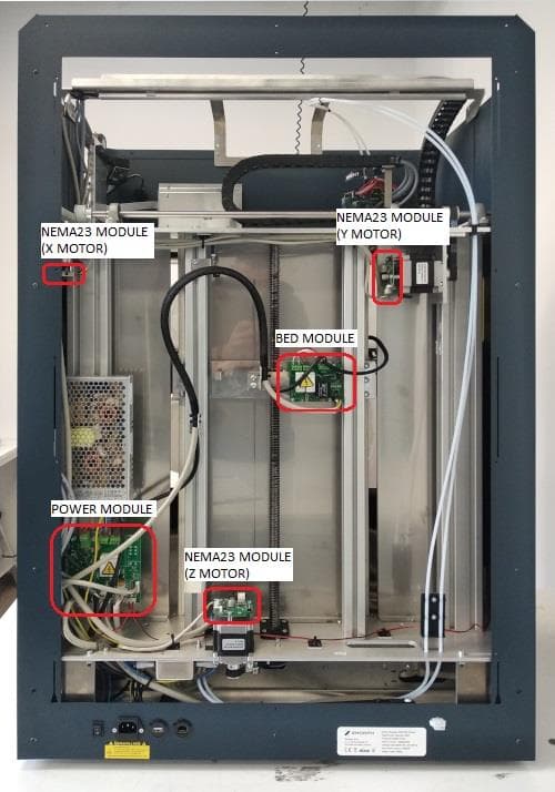
Click to zoom
Application Details
- Equipment Class
- DXX - Part 15 Low Power Communication Device Transmitter
- Date of Grant
- Dec 01, 2022
- Application Purpose
- Original Equipment
- Date of Application
- Nov 30, 2022
- Equipment Note
- Zmorph i500 3D Printer
- Frequency Range
- 13.56200000 - 13.56200000
- Company
- Zmorph S.A.
- Country
- Poland
Documents & Files
Document Text
Text extracted from the exhibit documents filed with the FCC. Open a document above to read the original.
Users Manual
ZMORPH i500 MANUAL GUIDE zmorph3d.com 2 Table of content Product Manual - ZMORPH i500 back to table of content >> 1. Introduction ..................................................................................................................................................... 4 2. Health and safety at work ................................................................................................................................ 4 2.1 Markings contained in the instructions guide and on the device ........................................................... 4 2.2 General safety information ..................................................................................................................... 6 2.3 Occupational hygiene ............................................................................................................................. 7 2.4 Electrical safety and risk .......................................................................................................................... 7 2.5 Safety and mechanical risks .................................................................................................................... 8 2.6 Risk of burns ............................................................................................................................................ 8 2.7 Instructions for safe storage and transport ............................................................................................. 8 2.8 Electromagnetic compatibility (EMC) ..................................................................................................... 9 2.9 Statement of Federal Communication Commision (FCC) ..................................................................... 10 3. Manufacturer’s warranty and liability .......................................................................................................... 11 3.1 Scope of the warranty ........................................................................................................................... 11 3.2 Acceptance of warranty claim ............................................................................................................... 12 3.3 Claim processing period ........................................................................................................................ 13 3.4 Zmorph’s liability................................................................................................................................... 13 4. What is Zmorph i500 ..................................................................................................................................... 14 5. How to use your Zmorph i500 printer ........................................................................................................... 15 6. Box content .................................................................................................................................................... 16 7. Machine specification .................................................................................................................................... 17 7.1 Overview ............................................................................................................................................... 17 7.2 Specification .......................................................................................................................................... 19 7.3 Components .......................................................................................................................................... 20 7.4 Functionalities .......................................................................................................................................... 23 8. Setting up Zmorph i500 ................................................................................................................................. 24 8.1 Location requirements .......................................................................................................................... 24 8.2 Unboxing ............................................................................................................................................... 25 3 Table of content Product Manual - ZMORPH i500 back to table of content >> 8.3 First use ................................................................................................................................................. 27 8.4 Safety features removal ........................................................................................................................ 28 8.5 Assembling air filtration system ............................................................................................................ 29 8.6 Assembling the garbage collector ......................................................................................................... 30 9. Maintenance.................................................................................................................................................. 32 9.1 Communication and File Delivery ......................................................................................................... 32 9.2 Loading the filament ............................................................................................................................. 34 9.3 Removing the filament .......................................................................................................................... 35 9.4 Calibration ............................................................................................................................................. 37 9.5 Starting the print ................................................................................................................................... 41 9.6 Removing a printout from the platform ......................................................................…
Text truncated - open the document above for the full version.
Cover Letter(s)
Date: 04/17/2018 VCB_F-01: Operating Procedures Form – FCC Authorization v02 Page 1 of 1 ZMORPH S.A. Federal Communications Commission Authorization and Evaluation Division 1435 Oakland Mills Road Columbia, MD 21046 Date: SUBJECT: FCC Application for (FCC ID: 2A9FXGC238615) To Whom It May Concern: We, the undersigned, hereby authorize Seong-Hun,Jeong in ICR Co.,Ltd on our behalf, to apply to the Federal Communications Commission on our equipment. Any and all acts carried out by ICR Co.,Ltd on our behalf shall have the same effect as acts of our own. This is to advise that we are in full compliance with the Anti- Drug Abuse Act. We, the applicant, are not subject to a denial of federal benefits pursuant to Section 5301 of the Anti-Drug Act of 1988, 21 USC853a, and no party to the application is subject to a denial of federal benefits pursuant to that section. Sincerely, (Must be signed by the person that is listed on the FCC Website) Client’s signature: Client’s name & title: Piotr Opara / materials and certification specialist Contact information / address: [email protected]
Cover Letter(s)
Date: 04/17/2018 VCB_F-01: Operating Procedures Form – FCC Confidentiality v03 Page 1 of 1 ZMORPH S.A. Federal Communications Commission Authorization and Evaluation Division Confidentiality Request regarding application for certification of FCC ID: 2A9FXGC238615 Pursuant to Sections 0.457 and 0.459 of the Commission’s Rules, we hereby request confidential treatment of information accompanying this application as outlined below: Type of Confidentiality Requested Exhibit Type ☐Short Term ☒Permanent Block Diagrams ☒Short Term External Photos ☒Short Term ☐Permanent* Internal Photos ☐Short Term ☒Permanent Operation Description ☐Short Term ☒Permanent Parts List/BOM ☐Short Term ☒Permanent Schematics ☒Short Term Test Setup Photos ☒Short Term ☐Permanent* User manual *Requires further justification before permanent confidentiality will be allowed. The above materials contain trade secrets and proprietary information not customarily released to the public. The public disclosure of these materials may be harmful to the applicant and provide unjustified benefits to its competitors. Permanent Confidentiality: The applicant requests the exhibits listed above as permanently confidential be withheld from public review due to materials that contain trade secrets and proprietary information not customarily released to the public. Short-Term Confidentiality: Pursuant to DA04-1705 June 15, 2004 of the Commission’s public notice, we also request temporary confidential treatment of information accompanying this application as outlined below for an initial period of 180 (ie- “45”, “90” or “180”) days. Sincerely, Client’s signature: Client’s name & title: Piotr Opara / materials and certification specialist Contact information / address: [email protected]
External Photos
Front Rear
Internal Photos
Internal of sample RFID Board and Antenna (front) RFID Board (back) Main Board (front) Main Board (back) Bed Module PCB (front) Bed Module PCB (back) Drawer Module (front) Drawer Module (back) Extruder Module (front) Extruder Module (back) Meanwell LRS50 MeanWell LRS150 NEMA23 Module (front) NEMA23 Module (back) Supply Filter Power Module (front) Power Module (back)
Test Report
페이지(page) : ( 2 )/( 총(Total) 17 ) ICRT-QPA-17-03 Rev.2 Report No. ICRT-TR-E223003-0A Contents 1. Applicant & Manufacturer & Test Laboratory Information .................................................................................. 4 1.1 Applicant information ........................................................................................................................................ 4 1.2 Manufacturer Information ................................................................................................................................. 4 1.3 Test Laboratory Information ............................................................................................................................ 4 2. Equipment under Test(EUT) Information ................................................................................................................. 5 2.1 General Information ........................................................................................................................................... 5 2.2 Additional Information ...................................................................................................................................... 5 2.3 Mode of operation during the test .................................................................................................................. 5 2.4 Modifications of EUT ......................................................................................................................................... 5 3. Test Summary ................................................................................................................................................................. 6 3.1 Test standards and results .............................................................................................................................. 6 3.2 Purpose of the test ............................................................................................................................................. 6 3.3 Test Methodology ............................................................................................................................................... 6 3.4 Configuration of Test System ......................................................................................................................... 6 3.5 Antenna requirement ......................................................................................................................................... 7 4. Used equipment on test ............................................................................................................................................... 8 5. 20 ㏈ Bandwidth ........................................................................................................................................................... 9 5.1 Operating environment ..................................................................................................................................... 9 5.2 Measurement method ........................................................................................................................................ 9 5.3 Test setup ............................................................................................................................................................. 9 5.4 Test data ............................................................................................................................................................... 9 6. Frequenct Stability Tolerance .................................................................................................................................. 10 6.1 Operating environment ................................................................................................................................... 10 6.2 Measurement method ...................................................................................................................................... 10 6.3 Test setup ........................................................................................................................................................... 10 6.4 Test data ............................................................................................................................................................. 10 7. Radiated Emissions .................................................................................................................................................... 11 7.1 Operating environment ................................................................................................................................... 11 7.2 Measurement method ...................................................................................................................................... 11 7.3 Test setup ........................................................................................................................................................... 11 7.4 Regulation .......................................................................................................................................................... 12 7.5 Test data for Radiated Electric Field Emissions ...................................................................................... 13 7.6 Spurious Emission Test.................................................................................................................................. 14 8. Power Line Conducted Emission ............................................................................................................................ 15 8.1 Operating environment ................................................................................................................................... 15 8.2 Measurement method ............................................................................................................................…
Text truncated - open the document above for the full version.
Test Report
ZMORPH S.A. Antenna Information Manufacturer Handsontec Antenna Type PCB Antenna Antenna Model RC522 Antenna Part Number N/A Antenna Frequency Range 13.56 MHz Antenna Input Power Limitation N/A Antenna Peak Gain N/A Antenna Dimension (LxHxW) 39 x 59.5 (mm) Antenna Photo Antenna Top View [With Ruler] ZMORPH S.A. Antenna Bottom View [With Ruler] Antenna size ZMORPH S.A. Antenna Pattern/Gain Measurement data/Table: As it is the antenna of DXX equipment, submission of information on gain value is exempted. Antenna Pattern/Measurement data
Test Report
1 www.handsontec.com Handson Technology Data Specs RC522 RFID Development Kit This RC522 RFID Development kit is based on NXP's a highly integrated reader/writer IC MFRC522 for contactless communication at 13.56 MHz. The MFRC522 reader supports ISO/IEC 14443 A/MIFARE and NTAG. The MFRC522’s internal transmitter is able to drive a reader/ writer antenna designed to communicate with ISO/IEC 14443A cards and transponders without additional active circuitry. The receiver module provides a robust and efficient implementation for demodulating and decoding signals from ISO/IEC 14443A compatible cards and transponders. SKU: MDU1040 Brief Data: Operating Voltage: 2.5V~3.3V. Operating/Standby current: 13~26mA/10~13mA. Operating Frequency: 13.56MHz. Supports ISO/IEC 14443A higher transfer speed communication up to 848 KBd. SPI bus speed up to 10Mbit/s. I2C-bus interface up to 400 kBd in Fast mode, up to 3400 kBd in High-speed mode. RS232 Serial UART up to 1228.8 kBd, with voltage levels dependant on pin voltage supply. Compatible with MIFARE and ISO 14443A cards. Typical operating distance in Read/Write mode up to 50 mm depending on the antenna size and tuning. 2 www.handsontec.com Interface Pins Function: Mechanical Dimension: P.S: This module does not support RFID cards which operate at 125KHz frequency range. It supports only the cards which operate at 13.56MHz frequency range. 3 www.handsontec.com Application Example with Arduino: Library download: Here’s the library you need for this project: 1. Download the RFID library here created by miguelbalboa 2. Unzip the RFID library 3. Install the RFID library in your Arduino IDE 4. Restart your Arduino IDE Arduino Circuit Connection: RC522 Pin Wiring to Arduino Un SDA Digital 10 SCK Digital 13 MOSI Digital 11 MISO Digital 12 IRQ unconnected GND GND RST Digital 9 3.3V Supply 3.3V Pin Wiring Reading Data from a RFID Tag: After having the circuit ready, go to File > Examples > MFRC522 > DumpInfo and upload the code. This code will be available in your Arduino IDE (after installing the RFID library). Then, open the serial monitor with 9600 baud. You should see something like the figure below: 4 www.handsontec.com Put the RFID card or the keychain to the reader. Let the reader and the tag closer until all the information is displayed. This is the information that you can read from the card, including the card UID that is highlighted in red. The information is stored in the memory that is divided into segments and blocks as you can see in the previous picture. 5 www.handsontec.com You have 1024 bytes of data storage divided into 16 sectors and each sector is protected by two different keys, A and B. Write down your UID card because you’ll need it later. In this case, Card UID: B0 AC 7E 7A. Upload the following code to the Arduino Board: ========================================================================= /* * * All the resources for this project: * Modified by Handson Technology * www.handsontec.com * Created by Handsontec Tech team * */ #include <SPI.h> #include <MFRC522.h> #define SS_PIN 10 #define RST_PIN 9 MFRC522 mfrc522(SS_PIN, RST_PIN); // Create MFRC522 instance. void setup() { Serial.begin(9600); // Initiate a serial communication SPI.begin(); // Initiate SPI bus mfrc522.PCD_Init(); // Initiate MFRC522 Serial.println("Put close your card to the reader..."); Serial.println(); } void loop() { // Look for new cards if ( ! mfrc522.PICC_IsNewCardPresent()) { return; } // Select one of the cards if ( ! mfrc522.PICC_ReadCardSerial()) { return; } //Show UID on serial monitor Serial.print("UID tag :"); String content= ""; byte letter; for (byte i = 0; i < mfrc522.uid.size; i++) { Serial.print(mfrc522.uid.uidByte[i] < 0x10 ? " 0" : " "); Serial.print(mfrc522.uid.uidByte[i], HEX); content.concat(String(mfrc522.uid.uidByte[i] < 0x10 ? " 0" : " ")); content.concat(String(mfrc522.uid.uidByte[i], HEX)); } Serial.println(); Serial.print("Message : "); content.toUpperCase(); 6 www.handsontec.com if (content.substring(1) == "B0 AC 7E 7A") //change here the UID of the card/cards that you want to give access { Serial.println("Authorized access"); Serial.println(); delay(3000); } else { Serial.println(" Access denied"); delay(3000); } } =========================================================================== In the piece of code above you need to change the if (content.substring(1) == “REPLACE WITH YOUR UID”) and type the UID card you’ve written previously. Demonstration: Now, upload the code to your Arduino and open the serial monitor. You will see the screen as below: Put the card you’ve chosen to give access (in this case with UID: B0 AC 7E 7A) near to the reader module and you’ll see: 7 www.handsontec.com Now if you put close another tag with another UID, the denial message will show up: This completed our initial testing & setup for RC522 RFID reader module, hope you found this tutorial useful. This RFID Development Package include: 1x RFID RC522 Reader Module 1x Credit card size RFID Card (M1 S50 IC Card) 1x RFID Keyring (M1 S50 Key tag) 1x 8-pin strait header connector 1x 8-pin right angle header connector Web Resource: MDU1040 RC522 Course Using the MF522 RFID Reader with the Arduino. MF1 S50 ISO/IEC14443A Contactless RFID Card MF1 S50 ISO/IEC14443A Contactless RFID Key Chain 8 www.handsontec.com Handsontec.com HandsOn Technology provides a multimedia and interactive platform for everyone interested in electronics. From beginner to diehard, from student to lecturer. Information, education, inspiration and entertainment. Analog and digital, practical and theoretical; software and hardware. HandsOn Technology support Open Source Hardware (OSHW) Development Platform. Learn : Design : Share www.handsontec.com 9 www.handsontec.com The Face behind our product quality... In a world of constant change and continuous technological development, a new or replacement product is never far away – and they all need to be tested. Ma…
Text truncated - open the document above for the full version.
Test Setup Photos
페이지(page) : ( 1 )/( 총 3 ) ICRT-QP-22-02 Rev.5 Report No. ICRT-TR-E223003-0A Test Setup Photo Test Setup Radiated measurement for Below 30 ㎒ (Front) Test Setup Radiated measurement for Below 30 ㎒ (Rear) 페이지(page) : ( 2 )/( 총 3 ) ICRT-QP-22-02 Rev.5 Report No. ICRT-TR-E223003-0A Test Setup Radiated measurement for below 1 ㎓ (Front) Test Setup Radiated measurement for below 1 ㎓ (Rear) 페이지(page) : ( 3 )/( 총 3 ) ICRT-QP-22-02 Rev.5 Report No. ICRT-TR-E223003-0A Test Setup Power Line Conducted Emission (Front) Test Setup Power Line Conducted Emission (Side)
Contact Information
Applicant
Piotr Opara
Test Firm
ICR Co., Ltd.Sim Sang-Woo
Technical Specifications
| # | Rule Parts | Frequency Range | Power Output |
|---|---|---|---|
| 1 | 15C | 13.562 MHz - 13.562 MHz | - |