2A9GC03664411000133PARHYS
ENGIE Lab CRIGEN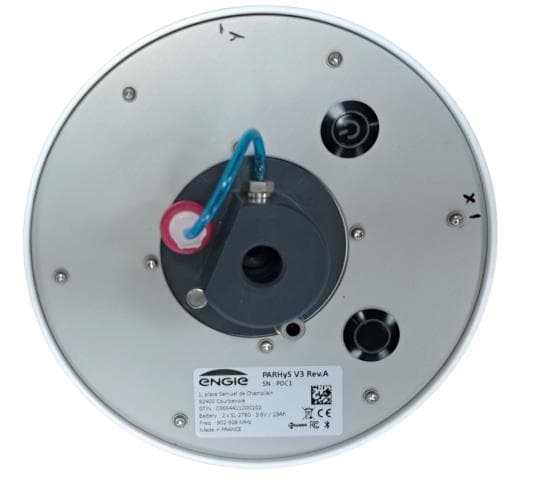
Click to zoom
Application Details
- Equipment Class
- DTS - Digital Transmission System
- Date of Grant
- Apr 26, 2023
- Application Purpose
- Original Equipment
- Date of Application
- Apr 26, 2023
- Equipment Note
- PARHYS
- Frequency Range
- 2402.00000000 - 2480.00000000
- Company
- ENGIE Lab CRIGEN
- Country
- France
Documents & Files
Document Text
Text extracted from the exhibit documents filed with the FCC. Open a document above to read the original.
Users Manual
Page 1/2 ANTENNA DESCRIPTION Applicant: ENGIE Lab CRIGEN Device model: PARHYS SENSOR 1.1 RF antenna 1 (868-915MHz) Description: Photo: Page 2/2 1.2 RF antenna 1 (BLE) Description: Manufacturer : PULSE P/N: ANT3216A063R2400A Measured antenna gain inside equipment: -3.5dBi Photo:
Users Manual
ENGIE Reserved ENGIE 2023 1 Place Samuel de Champlain – 92400 COURBEVOIE - FRANCE Permanent Analyses of Renewable Hydrogen with Sensors User Guide Page 2 This document is the exclusive property of ENGIE. Any inappropriate use contrary to its original purpose, any dissemination, part or full publication of this document is prohibited without the prior written consent of ENGIE owner of this document. TABLE OF CONTENTS 1. OBJECTIVE ...........................................................................................................2 2. SYSTEM COMPONENTS......................................................................................3 3. INSTALLATION INSTRUCTIONS ..........................................................................4 4. PROBLEMS AND SOLUTIONS DURING INSTALLATION ...................................7 5. PRODUCT SPECIFICATION SHEET ....................................................................8 6. GENERAL INFORMATION – CERTIFICATION ....................................................9 Hazard warnings and safety symbols Information in this manual that may affect the safety of users. If the equipment is used in a manner not specified by the manufacturer, the protection provided by the equipment may be impaired Important/useful information and instructions are shown clearly throughout the manual in a note format. Page 3 This document is the exclusive property of ENGIE. Any inappropriate use contrary to its original purpose, any dissemination, part or full publication of this document is prohibited without the prior written consent of ENGIE owner of this document. 1. OBJECTIVE Hydrogen is a key component of the energy transition movement and natural hydrogen could be part of it. Indeed, emanations coming out of the ground have been detected in several places in the world. However, this molecular hydrogen is extremely diffuse and requires dedicated instrumentation to be detected. PARHyS instrument is designed to remotely and continuously monitor natural hydrogen emanations in the soil at a depth up to 1 meter. This measurement may be realized at regular interval (1h to 24h). PARHyS use LoRaWan network (public or private) and Bluetooth communications. PARHyS also allows the recovery of gas from the ground via a balloon that can be placed at the vent. The various components of the gas other than hydrogen can thus be measured by gas chromatography. 2. SYSTEM COMPONENTS Bottom view of PARHyS sensor ① Globe ② Inox sampling tubing ③ On/Off button ④ Bluetooth button ⑤ Identification label ⑥ Air vent silencer ⑦ Gas path ⑧ Hydrophobic filter Page 4 This document is the exclusive property of ENGIE. Any inappropriate use contrary to its original purpose, any dissemination, part or full publication of this document is prohibited without the prior written consent of ENGIE owner of this document. 3. INSTALLATION INSTRUCTIONS Parts included in the package • PARHyS sensor packed. • Inox sampling tubing not plugged. • User Guide. Tools box (not included in the package) • 2 Thionyl Chloride 3.6 V – Size D. • Screwdriver Philips medium to remove/install the top of the globe. • Portable perforator. • Drill 12x1000 mm. • Smartphone Android 10+. • Smartphone Apps, • Option: Gas sampling flask or bag with a minimum volume of 0.5 l. First preparation before installation • Remove the 6 screws on the bottom ① to remove the top of the globe ②. Page 5 This document is the exclusive property of ENGIE. Any inappropriate use contrary to its original purpose, any dissemination, part or full publication of this document is prohibited without the prior written consent of ENGIE owner of this document. • Place the 2 batteries - type 3.6V-19Ah Thionyl Chloride respecting the polarities ③. • Replace the top of the globe. • Switch the PARHyS sensor by pushing the On/Off button: o 2 LED flashing consecutively. o When PARHyS sensor is started (around xx seconds) : rapid flashing of the power button LED. • Start Apps Nanotech on your Smartphone (refer to Nanotech Apps documentation load on www.website. Crigen.com). • Pair PARHyS sensor by pressing the Bluetooth button. o BLE connectable: slow flashing of the BLE button LED. o BLE connected: rapid flashing of the BLE button LED. • If PARHyS Sensor is connected to the Gateway, the 2 LED simultaneous status are : o Transmission of the join request: 1 flash. o Failure of the join procedure: 2 flashes o Reception of the join successful: 4 flashes. o First frame received: 6 flashes. • Plug the sampling inox tubing with the globe ④. A mark on the sampling inox tubing indicates the ideal pushing length. The two O-rings must not be removed from their location. They are shown to indicate that providing the gas tight seal their presence should be checked. Installing PARHyS sensor into the soil Check on your smartphone that the module has been paired. • A hole about 1000 mm depth and 12 mm in diameter is drilled in the ground with a portable perforator. • Insert sampling tubing into the hole to a depth of 1000 mm (or less). Ensure the path gas tube is not crushed, around 20 cm up to the soil. Page 6 This document is the exclusive property of ENGIE. Any inappropriate use contrary to its original purpose, any dissemination, part or full publication of this document is prohibited without the prior written consent of ENGIE owner of this document. Measurement procedure (refer to Smartphone Apps User Guide) • Start the Manual measurement mode in the Smartphone Apps: data retrieved as a csv file on the Smartphone directly. • Start the Automatic measurement mode in the Smartphone Apps: data retrieved every hour from a server. I could be necessary to Push Bluetooth button again since for energy saving the BLE switches off. Balloon/bag installation procedure PARHyS makes it possible to collect a punctual sample of gas from the soil for chromatographic analysis with a balloon. • Push Bluetooth button at the bottom of globe. • Start up the Smartphone Apps Nanotech. • Stop th…
Text truncated - open the document above for the full version.
External Photos
Page 1/1 EXTERNAL PHOTOS OF TESTED EUT Applicant: ENGIE Lab CRIGEN Device model: PARHYS SENSOR
ID Label/Location Info
Page 1/1 PRODUCT LABELING Applicant: ENGIE Lab CRIGEN Device model: PARHYS SENSOR
Internal Photos
Page 1/2 INTERNAL PHOTOS OF TESTED EUT Applicant: ENGIE Lab CRIGEN Device model: PARHYS SENSOR Page 2/2
RF Exposure Info
COORDONNEES SMEE TEL : 04 76 65 76 50 385, Rue Renè Rambaud, ZA le Parvis 2 FAX : 04 76 66 18 30 38500 VOIRON - France SAS au capital de 50 000 € / RC Grenoble B534 796 453 / SIRET 534 796 453 00015 / code APE 7490B / n° TVA : FR 59 534 796 453 RF Exposure Considerations for FCC ID: 2A9GC03664411000133 The calculation of the MPE is as following: Prediction of MPE limit at a prediction distance: S= ² . . 4 . R G P = ² . . 4 . . . R P R I E S: Power density (mW/cm²) P: Peak output power at antenna terminal (mW) G: Numerical Antenna gain R: Distance of radiation to antenna (cm) MPE calculation (1): No simultaneous RF transmission Conclusion: Therefore, the device complies with FCC’s RF radiation exposure limits for general population for a mobile device. Certified By Laurent CHAPUS (Agent for this device) SMEE 385, Rue René Rambaud ZA Le Parvis 2 38500 Voiron - France [email protected] FCC Registration Number: 0020356952 (FRN) Applicant for this device: ENGIE Lab CRIGEN 4 RUE JOSEPHINE BAKER 93240 STAINS - France [email protected] +33149 22 58 75 FRN: 0033106147 Frequency (MHz) Maximum E.I.R.P. (mW) R (cm) Power Density S (mW/cm²) MPE limit (mW/cm²) % of limit Limit (%) Verdict 2402-2480 1.12 20 0.00022 1.0 0.022 100% Below MPE limit for uncontrolle d exposure Simultaneous transmissions SUM = N/A (1) 100%
Test Report
Rapport d’essais / Test Report N° : 14768-FCC-ISED-2 Page 1 / 30 COORDONNEES SMEE TEL : 04 76 65 76 50 385, Rue René Rambaud, ZA Le Parvis 2 FAX : 04 76 66 18 30 38500 VOIRON - France SAS au capital de 50 000 € / RC Grenoble B534 796 453 / SIRET 534 796 453 00015 / code APE 7490B / n° TVA : FR 59 534 796 453 FCC Test Firm Designation Number: FR0014 ISED Wireless Device Testing Laboratory CAB Number: FR0004 Matériel testé : Equipment under test: ENGIE / PARHyS Sensor (Trademark / Marketing name or product reference) Demandeur de certification : Applicant for certification: ENGIE Lab CRIGEN 4, Rue Josephine Baker 93240 STAINS – FRANCE Client : Customer: NEMEUS 36 rue des landelles 35510 – Cesson-Sevigne – France Numéro d’affaire : Work number : 092022-25649 Référence de la proposition : Proposal number: 14768 Date de l’essai : Date of test: Du 7 au 24 Novembre 2022 November 7 th to 24 th ,2022 Objectif des essais : Test purpose: EMC qualification accordingly to following standards: - CFR 47, FCC Part 15, Subpart C (Chapter 15.247 - Operation within the bands 902–928 MHz, 2400–2483.5 MHz, and 5725–5850 MHz) - Industry Canada RSS-247, Issue 2 (Digital Transmission Systems Operating in the Bands 902–928 MHz) Measurement standards: ANSI C63.10 (2013) Lieu du test: Test location: SMEE, 385 Rue René Rambaud 38500 VOIRON - France Test réalisé par : Test realized by: Chemseddine KERMICHE Conclusion : Conclusion: L’équipement satisfait aux prescriptions et essais des normes citées en référence. The appliance complies with requirements and tests of above mentioned standards. Ed. Date Modifications / Pages Written by: Visa Approved by: Visa 1 2 January 9 th , 2023 March 9 th , 2023 Initial Edition Additional information Chemseddine KERMICHE Test operator Laurent CHAPUS Technical Manager La copie de ce document n'est permise que sous sa forme intégrale. Ce document est le résultat d’essais effectués sur un échantillon. Il ne préjuge pas de la conformité de l’ensemble des produits fabriqués à l’objet essayé. Pour la déclaration de conformité de l'équipement, il n'est pas tenu compte de l'incertitude de mesure. Cette nouvelle édition de ce rapport annule et remplace l’édition précédente. Les modifications apportées à une nouvelle édition de ce rapport sont signalées par un trait vertical à gauche de la page. This document shall not be reproduced, except in full. This document contains results related only to the item tested. It does not imply the conformity of the whole production to the item tested. For the declaration of conformity of the equipment, the measurement uncertainty is not taken into account. This new edition of this report cancels and replaces the previous edition. Changes made to a new edition of this report are indicated by a vertical line to the left of the page. Accréditation N° 1-6356 Portée disponible sur : Scope available on : www.cofrac.fr Page 2 / 30 Rapport d’essai / Test Report N° : 14768-FCC-ISED-2 Page 2 / 30 Contents 1. NORMATIVES REFERENCES ......................................................................................................... 3 2. TEST SYNTHESIS ............................................................................................................................ 4 3. EQUIPMENT UNDER TEST (EUT) ................................................................................................... 5 4. TEST CONDITIONS .......................................................................................................................... 5 5. MODIFICATIONS OF THE EUT ........................................................................................................ 5 6. SPECIAL ACCESSORY .................................................................................................................... 6 7. MEASUREMENT UNCERTAINTY .................................................................................................... 6 8. FIELD STRENGTH CALCULATION .................................................................................................. 6 9. TEST SETUP DIAGRAM ................................................................................................................... 7 10. DTS BANDWIDTH ......................................................................................................................... 8 11. MAXIMUM PEAK OUTPUT POWER ........................................................................................... 10 12. MAXIMUM POWER SPECTRAL DENSITY LEVEL IN THE FUNDAMENTAL EMISSION ........... 12 13. UNWANTED EMISSIONS IN NON-RESTRICTED FREQUENCY BANDS (RADIATED EMISSIONS) .......................................................................................................................................... 15 14. UNWANTED EMISSIONS IN RESTRICTED FREQUENCY BANDS ........................................... 17 15. OCCUPIED BANDWIDTH (99%) ................................................................................................. 27 16. TEST EQUIPMENT LIST ............................................................................................................. 30 Page 3 / 30 Rapport d’essai / Test Report N° : 14768-FCC-ISED-2 Page 3 / 30 1. Normatives References FCC qualification according to: Standards Applied Title ANSI C63.10 (2013) X American National Standard for Testing Unlicensed Wireless Devices CFR47, Part 15 (November 2022) X Telecommunication – Federal Communication Commission – Radio frequency devices, Sections 15.207 / 15.209 / 15.247 ISED qualification according to: Standards Applied Title RSS-Gen (Issue 5/2018, amendments 2019 and 2021) X General Requirements and Information for the Certification of Radio Apparatus RSS-247 (Issue2/2017) X Digital Transmission Systems (DTSs), Frequency Hopping Systems (FHSs) and Licence-Exempt Local Area Network (LE-LAN) Devices Note: Following guidance are used - DTS Measurement Guidance 558074 D01 v05r02 - Determining ERP and EIRP Guidance 412172 …
Text truncated - open the document above for the full version.
Test Report
Rapport d’essais / Test Report N° : 14768-FCC-ISED-1 Page 1 / 13 COORDONNEES SMEE TEL : 04 76 65 76 50 385 rue René Rambaud – ZA Le Parvis 2 FAX : 04 76 66 18 30 38500 VOIRON - France SAS au capital de 50 000 € / RC Grenoble B534 796 453 / SIRET 534 796 453 00023 / code APE 7490B / n° TVA : FR 59 534 796 453 FCC Test Firm Designation Number: FR0014 ISED Wireless Device Testing Laboratory CAB Number: FR0004 Matériel testé : Equipment under test: ENGIE / PARHyS Sensor (Trademark / Marketing name or product reference) Demandeur de certification : Applicant for certification: ENGIE Lab CRIGEN 4, Rue Josephine Baker 93240 STAINS – FRANCE Client : Customer: NEMEUS 36 rue des landelles 35510 – Cesson-Sevigne – France Référence de la proposition : Proposal number: 092022-25649 Numéro d’affaire : Work number : 14768 Date de l’essai : Date of test: Du 7 au 24 Novembre 2022 November 7 th to 24 th ,2022 Objectif des essais : Test purpose: EMC qualification according to standard CFR 47, FCC Part 15, Subpart B & Industry Canada ICES-003 (Issue 7/2020) Equipment type: Class B digital device Measurement standard: ANSI C63.4 (2014+A1/2017) Lieu du test: Test location: SMEE, 385 rue René Rambaud 38500 VOIRON - France Test réalisé par : Test realized by: Chemseddine KERMICHE Conclusion : Conclusion: L’équipement satisfait aux prescriptions et essais des normes citées en référence. The appliance complies with requirements and tests of above mentioned standards. Ed. Date Modifications / Pages Written by: Approved by: Visa 1 2 January 9 th , 2023 April 26 th , 2026 Initial Edition Additional information Chemseddine KERMICHE Test operator Laurent CHAPUS Technical Manager La copie de ce document n'est permise que sous sa forme intégrale. Ce document est le résultat d’essais effectués sur un échantillon. Il ne préjuge pas de la conformité de l’ensemble des produits fabriqués à l’objet essayé. Pour la déclaration de conformité de l'équipement, il n'est pas tenu compte de l'incertitude de mesure. Cette nouvelle édition de ce rapport annule et remplace l’édition précédente. Les modifications apportées à une nouvelle édition de ce rapport sont signalées par un trait vertical à gauche de la page. This document shall not be reproduced, except in full. This document contains results related only to the item tested. It does not imply the conformity of the whole production to the item tested. For the declaration of conformity of the equipment, the measurement uncertainty is not taken into account. This new edition of this report cancels and replaces the previous edition. Changes made to a new edition of this report are indicated by a vertical line to the left of the page. Accréditation N° 1-6356 Portée disponible sur : Scope available on : www.cofrac.fr Test Report Page 2 / 13 Rapport d’essai / Test Report N° : 14768-FCC-ISED-1 Page 2 / 13 Sommaire / Contents 1. NORMATIVE REFERENCES ............................................................................................................ 3 2. TEST SYNTHESIS ............................................................................................................................ 4 3. EQUIPMENT UNDER TEST (EUT) ................................................................................................... 5 4. TEST CONDITIONS .......................................................................................................................... 7 5. MODIFICATIONS OF THE EUT ........................................................................................................ 7 6. SPECIAL ACCESSORIES ................................................................................................................. 7 7. MEASUREMENT UNCERTAINTY ..................................................................................................... 7 8. FIELD STRENGTH CALCULATION .................................................................................................. 7 9. RADIATED EMISSION MEASUREMENT (30MHZ-18GHZ) .............................................................. 8 Test Report Page 3 / 13 Rapport d’essai / Test Report N° : 14768-FCC-ISED-1 Page 3 / 13 1. Normative references FCC qualification according to: Standards Applied Title ANSI C63.4 (2014 + A1/20017) X American National Standard for Methods of Measurement of Radio- Noise Emissions from Low-Voltage Electrical and Electronic Equipment in the Range of 9 kHz to 40 GHz. CFR47, Part 15 (November 2022) X Telecommunication – Federal Communication Commission – Radio frequency devices, Subpart B — Unintentional Radiators. Sections 15.107 / 15.109 ISED Canada qualification according to: Standards Applied Title ANSI C63.4 (2014 + A1/20017) X American National Standard for Methods of Measurement of Radio- Noise Emissions from Low-Voltage Electrical and Electronic Equipment in the Range of 9 kHz to 40 GHz. ICES-003 (Issue 7 - 2020) X ISED Canada ICES-003 (Information Technology Equipment (ITE)) — Limits and methods of measurement. Deviation from the standard: None. Test Report Page 4 / 13 Rapport d’essai / Test Report N° : 14768-FCC-ISED-1 Page 4 / 13 2. Test synthesis Class B digital device: ESSAI D’EMISSION / EMISSION TEST LIMITES / LIMITS FCC CFR 47, PART 15 RESULTATS / RESULTS Conducted emissions at power supply ports 150kHz-30MHz Frequency Quasi-Peak (dBμV) Average (dBμV) N/A (1) 150-500kHz 66 \ 56 56 \ 46 0.5-5MHz 56 46 5-30MHz 60 50 Radiated emissions 30MHz-18GHz Measure at 3m PASS Frequency Limit (dBμV/m) / Detector 30-88MHz 40.0 / QP 88-216MHz 43.5 / QP 216-960MHz 46.0 / QP 960MHz-1GHz 54.0 / QP Above 1GHz 54.0 / AV 74.0 / PK ESSAI D’EMISSION / EMISSION TEST LIMITES / LIMITS ICES-003 RESULTATS / RESULTS Conducted emissions at power supply ports 150kHz-30MHz Frequency Quasi-Peak (dBμV) Average (dBμV) PASS 150-500kHz 66 \ 56 56 \ 46 0.5-5MHz 56 46 5-30MHz 60 50 Radiated emissions 30MHz-2GHz Measure at 3m PASS Frequency Limit (dBμV/m) / Detector 30-88MHz 40.0 / QP 88-216MHz 43.5 / QP 216-230MHz 4…
Text truncated - open the document above for the full version.
Test Setup Photos
Page 1/3 TEST SETUP PHOTOS Applicant: ENGIE Lab CRIGEN Device model: PARHYS SENSOR CONDUCTED EMISSIONS N/A N/A Page 2/3 RADIATED EMISSIONS (FREQ < 1GHz) Page 3/3 RADIATED EMISSIONS (FREQ > 1GHz)
Contact Information
Applicant
Adeline DUTERQUE(Head of ENGIE Lab CRIGEN)
Test Firm
SMEELaurent Chapus
[email protected]+33 4 76 65 76 50
Technical Specifications
| # | Rule Parts | Frequency Range | Power Output |
|---|---|---|---|
| 1 | 15C | 2.40 GHz - 2.48 GHz | 2.51 mW |