2A9HZ-LWM8-5WIRELESS MICROPHONE
NATIONAL PUBLIC SEATING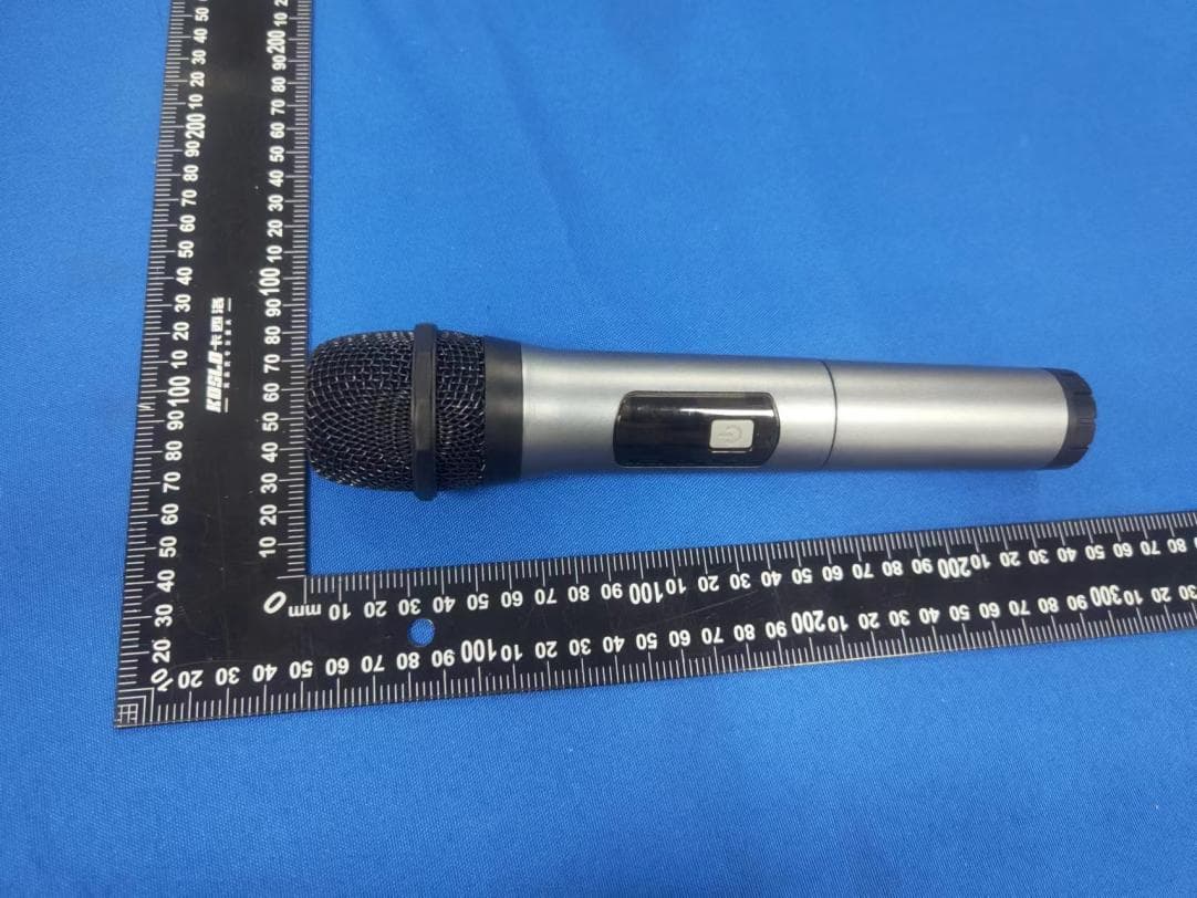
Click to zoom
Application Details
- Equipment Class
- DWM - Part 15 Wireless Microphone
- Date of Grant
- Jan 08, 2023
- Application Purpose
- Original Equipment
- Date of Application
- Jan 08, 2023
- Equipment Note
- WIRELESS MICROPHONE
- Frequency Range
- 657.20000000 - 662.60000000
- Company
- NATIONAL PUBLIC SEATING
- Country
- United States
Documents & Files
Document Text
Text extracted from the exhibit documents filed with the FCC. Open a document above to read the original.
Users Manual
Instruction manual 1、Wireless microphone, also known as wireless microphone, it can achieve sound restoration and expansion, compared with wired microphone is more simple, more and more favored by consumers, is widely used in KTV, audio-visual room, conference room and other occasions. 2、How wireless microphones work: Wireless microphones are mainly composed of transmitting parts and receiving parts. The emitting part is powered by a battery, and the microphone converts the sound into an audio electrical signal, and after internal circuit processing, it transmits radio waves containing audio information into the surrounding space. The receiving part is generally powered by the mains, and the radio waves emitted by the transmitting part are received by the receiving antenna, and the audio signal is extracted through the processing of the internal circuit, and sent to the sound reinforcement system through the output signal line, so as to complete the wireless transmission of the audio signal. 3、Impedance matching When using a wireless microphone, the output impedance of the wireless microphone and the input impedance of the amplifier are the same as the match of *, and if the mismatch ratio is above 3:1, it will affect the transmission effect. For example, when a 50Ω wireless microphone is connected to an amplifier with an input impedance of 150Ω, although the output can be increased by nearly 7Db, the sound of high and low frequencies will be significantly lost. 4、Working distance and proximity effect Generally, the working distance between the wireless microphone and the mouth is 750px- -1000px, if the distance is too far, the echo will increase, and the noise will increase relatively. If the working distance is too close, it will be distorted due to too strong signal, and the low-frequency sound will be too heavy and affect the intelligibility of language. This is because directional microphones have a "proximity effect", that is, when speaking at close range, the low-frequency sound is significantly improved. However, sometimes singers deliberately use "near-talk" to make the singing effect more beautiful and beautiful. 5、The angle between the sound source and the wireless microphone Each wireless microphone has its effective angle, and the general sound source should be aligned with the center line of the wireless microphone, and the greater the declination angle between the two, the greater the treble loss. Sometimes when using a wireless microphone, there is a "boom" sound, and then it can be mitigated by deflecting it by some angles. 6、Wireless microphone position and height When amplifying, the wireless microphone should not be placed close to the speaker or aligned with the speaker first, otherwise it will cause howling. The height of the wireless microphone should be determined by the height of the sound source, if one person speaks or several people sing, the height of the wireless microphone should be consistent with the singer's mouth; When there are a large number of people, the wireless microphone should be placed at an average height, and the position of the singer and accompaniment and various instruments in the team should be appropriately arranged, so as not to make the sound too loud, light and too light, and to make all the sound within the effective angle of the wireless microphone. Wireless microphones should be protected from knocks or falls during use. It is not advisable to test the microphone by blowing or tapping, otherwise it is easy to damage the wireless microphone. When using wireless microphones outdoors or recording voice, you should use a draft shield to avoid recording "pops" of the wind. The draft shield also prevents dust from staining the wireless microphone. 7、Remove the battery in time when not in use Wireless microphones, such as the LWM85-6-7, are battery-powered. If the voltage drops, the sensitivity decreases and the distortion increases. Therefore, when the sound becomes worse, the battery voltage should be checked, the power switch should be turned off when the wireless microphone is not in use, and the battery should be removed when it is not used for a long time. Use for multimedia audio, outdoor mobile audio, home Karaoke audio Head : Moving tyle/professional KTV grade microphone core Carrier frequency range: 657.2M / 662.6MHz (4 channels) Dynamic range: ≥60dB Distortion: ≤3% Signal-to-noise ratio: ≥60dB Operating distance: >30m Operating temperature range: 3°~45° Audio usage range: 45Hz -16KHz±3Db System output: 300mV for handheld channel, 36mV for beltpack channel (10Mv 1KHzin) Application: High-end mobile speakers / super stereo / jukebox etc. Type: One-two wireless microphone Transmitter Carrier output power: <10dBm Modulation method: FM Maximum frequency deviation: ±75KHz Power supply voltage: 1.5V x 2 Power consumption: ≤150Ma Net weight: 282g FCC Caution. This device complies with part 15 of the FCC Rules. Operation is subject to the following two conditions: (1) This device may not cause harmful interference, and (2) this device must accept any interference received, including interference that may cause undesired operation. Any Changes or modifications not expressly approved by the party responsible for compliance could void the user's authority to operate the equipment. Note: This equipment has been tested and found to comply with the limits for a Class B digital device, pursuant to part 15 of the FCC Rules. These limits are designed to provide reasonable protection against harmful interference in a residential installation. This equipment generates uses and can radiate radio frequency energy and, if not installed and used in accordance with the instructions, may cause harmful interference to radio communications. However, there is no guarantee that interference will not occur in a particular installation. If this equipment does cause harmful interference to radio or television reception, which can be determined by turning the e…
Text truncated - open the document above for the full version.
Cover Letter(s)
Sincerely, Name/Title: Mark Zou/Manager Company: NATIONAL PUBLIC SEATING Address: 149 ENTIN ROAD CLIFTON NJ 07014 New Jersey United States Phone: (8) 615-0268 83824 Fax: N/A E-Mail: [email protected]
External Photos
FCC ID: 2A9HZ-LWM8-5
ID Label/Location Info
FCC ID: 2A9HZ-LWM8-5 WIRELESS MICROPHONE Model: LWM8-5 FCC ID: 2A9HZ-LWM8-5 NATIONAL PUBLIC SEATING
Internal Photos
FCC ID: 2A9HZ-LWM-5 Antenna
RF Exposure Info
RF Exposure evaluation FCC ID: 2A9HZ-LWM8-5 According to 447498 D01 General RF Exposure Guidance v06 The 1-g and 10-g SAR test exclusion thresholds for 100 MHz to 6 GHz at test separation distances ≤ 50 mm are determined by: [(max. power of channel, including tune-up tolerance, mW)/(min. test separation distance, mm)] ·[√f(GHz)] ≤ 3.0 for 1-g SAR and ≤ 7.5 for 10-g extremity SAR, where: f(GHz) is the RF channel transmit frequency in GHz Power and distance are rounded to the nearest mW and mm before calculation The result is rounded to one decimal place for comparison Worse case is as below: [ (6+1)dBm (5mW) output power] (5/5) ·[√0.6572(GHz)]= 0.81 <3.0 for 1-g SAR Then SAR evaluation is not required
Test Report
专业天线服务商 深圳市飞敏科技有限公司 SHENZHEN FEIMIN TECHNOLOGY CO.,LTD. 项目型号 天线型号 测 试 魏月娥 审 核 夏兴喜 日 期 2022-09-08 天线测试报告 Antenna test report SHENZHEN FEIMIN TECHNOLOGY CO.,LTD. TEL:0755-23035723 Mail:[email protected] URL:www.fmant.cn 测试设备和测试环境 Test equipment and test environment SHENZHEN FEIMIN TECHNOLOGY CO.,LTD. TEL:0755-23035723 Mail:[email protected] URL:www.fmant.cn 测试设备 Test equipment 无源指标 增益 效率 3D方向图 有源指标 TRP总辐射功率 TIS总接收灵敏度 探头微波暗室 频率:0.4GHz至6GHz 主要测试指标 SHENZHEN FEIMIN TECHNOLOGY CO.,LTD. TEL:0755-23035723 Mail:[email protected] URL:www.fmant.cn 测试设备 Test equipment Agilent E5071C矢量网络分析仪 频率:300 kHz至8.5GHz R&S CMW500 宽带无线通信测试仪 GSM/3G/4G WIFI/ Bluetooth NB-IoT SHENZHEN FEIMIN TECHNOLOGY CO.,LTD. TEL:0755-23035723 Mail:[email protected] URL:www.fmant.cn 测试拍照 Test photos SHENZHEN FEIMIN TECHNOLOGY CO.,LTD. TEL:0755-23035723 Mail:[email protected] URL:www.fmant.cn 天线安装位置 Passive antenna data SHENZHEN FEIMIN TECHNOLOGY CO.,LTD. TEL:0755-23035723 Mail:[email protected] URL:www.fmant.cn 天线驻波比 Antenna SWR SHENZHEN FEIMIN TECHNOLOGY CO.,LTD. TEL:0755-23035723 Mail:[email protected] URL:www.fmant.cn 天线回波损耗 Antenna Return loss SHENZHEN FEIMIN TECHNOLOGY CO.,LTD. TEL:0755-23035723 Mail:[email protected] URL:www.fmant.cn 天线增益与效率 Antenna gain and efficiency SHENZHEN FEIMIN TECHNOLOGY CO.,LTD. TEL:0755-23035723 Mail:[email protected] URL:www.fmant.cn 天线 Freq(MHz) Efficienc y (%) Gian(dBi) A 657 MHz 7.55 -10.48 657.5 MHz 7.6 -10.41 658 MHz 7.67 -10.33 658.5 MHz 7.73 -10.24 659 MHz 7.79 -10.18 660 MHz 7.86 -10.1 B 660.5 MHz 7.24 -10.33 661 MHz 7.26 -10.41 661.5 MHz 7.27 -10.47 662 MHz 7.25 -10.51 662.5 MHz 7.27 -10.49 663 MHz 7.28 -10.48 插入图片1 插入图片2 插入图片3 插入图片4 天线辐射方向图 Antenna Radiation Pattern SHENZHEN FEIMIN TECHNOLOGY CO.,LTD. TEL:0755-23035723 Mail:[email protected] URL:www.fmant.cn 插入图片1 插入图片2 插入图片3 插入图片4 天线辐射方向图 Antenna Radiation Pattern SHENZHEN FEIMIN TECHNOLOGY CO.,LTD. TEL:0755-23035723 Mail:[email protected] URL:www.fmant.cn 插入图片1 插入图片2 插入图片3 插入图片4 天线辐射方向图 Antenna Radiation Pattern SHENZHEN FEIMIN TECHNOLOGY CO.,LTD. TEL:0755-23035723 Mail:[email protected] URL:www.fmant.cn 深圳市宝安区西乡固戍恒南一路C栋303 TEL:(86)755-23035723. FAX:0755-23036702 E-mail:[email protected] ADD: 303,building C,GUSHU Hengnan Road,Xixiang,Baoan district Shenzhen Thanks for your support! 感谢您的支持!
Test Report
Page 1 of 37 TEST REPORT FCC ID: 2A9HZ-LWM8-5 Product : WIRELESS MICROPHONE Model Name : LWM8-5, LWM8-6, LWM8-7 Brand : CALIFONE Report No. : PTC22080106601E-FC01 Sample ID : PTC22080106601E-FC01# Prepared for NATIONAL PUBLIC SEATING 149 ENTIN ROAD CLIFTON NJ 07014 New Jersey United States Prepared by Precise Testing & Certification Co., Ltd Building 1, No. 6, Tongxin Road, Dongcheng Street, Dongguan, Guangdong, China Report No.: PTC22080106601E-FC01 Page 2 of 37 1 TEST RESULT CERTIFICATION Applicant’s name : NATIONAL PUBLIC SEATING Address : 149 ENTIN ROAD CLIFTON NJ 07014 New Jersey United States Manufacture's name : NINGBO RIXING ELECTRONICS CO.,LTD Address : No. 495 SHIDAI ROAD, WUXIANG TOWN, NINGBO,CHINA Product name : WIRELESS MICROPHONE Model name : LWM8-5,LWM8-6,LWM8-7 Standards : FCC CFR47 Part 15 Section 15.236 Test procedure : ANSI C63.10:2013 Test Date : August 26, 2022 to September 24, 2022 Date of Issue : September 25, 2022 Test Result : Pass This device described above has been tested by PTC, and the test results show that the equipment under test (EUT) is in compliance with the FCC requirements. And it is applicable only to the tested sample identified in the report. This report shall not be reproduced except in full, without the written approval of PTC, this document may be altered or revised by PTC, personal only, and shall be noted in the revision of the document. Test Engineer: Leo Yang / Engineer Technical Manager: Ronnie Liu / Manager Report No.: PTC22080106601E-FC01 Page 3 of 37 Contents Page 1 TEST RESULT CERTIFICATION .............................................................................................................................. 2 2 TEST SUMMARY ......................................................................................................................................................... 5 3 TEST FACILITY ............................................................................................................................................................ 6 4 GENERAL INFORMATION ........................................................................................................................................ 7 4.1 GENERAL DESCRIPTION OF E.U.T. .................................................................................................................... 7 4.2 TEST MODE ........................................................................................................................................................ 8 5 EQUIPMENT DURING TEST ..................................................................................................................................... 9 5.1 EQUIPMENTS LIST............................................................................................................................................... 9 5.2 MEASUREMENT UNCERTAINTY ......................................................................................................................... 11 5.3 DESCRIPTION OF SUPPORT UNITS ................................................................................................................... 12 6 CONDUCTED EMISSION ......................................................................................................................................... 13 6.1 E.U.T. OPERATION ........................................................................................................................................... 13 6.2 EUT SETUP ...................................................................................................................................................... 13 6.3 TEST SET-UP (BLOCK DIAGRAM OF CONFIGURATION) .................................................................................. 14 6.4 MEASUREMENT PROCEDURE: .......................................................................................................................... 14 6.5 CONDUCTED EMISSION LIMIT ........................................................................................................................... 14 6.6 MEASUREMENT DESCRIPTION .......................................................................................................................... 14 6.7 CONDUCTED EMISSION TEST RESULT ............................................................................................................. 14 7 RF POWER OUTPUT ................................................................................................................................................ 15 7.1 TEST PROCEDURE ............................................................................................................................................ 15 7.2 TEST RESULT: .................................................................................................................................................. 16 8 OCCUPIED BANDWIDTH MEASUREMENT ........................................................................................................ 18 8.1 TEST PROCEDURE ............................................................................................................................................ 18 8.2 TEST RESULT ................................................................................................................................................... 18 9 NECESSARY BANDWIDTH .................................................................................................................................... 21 9.1 TEST PROCEDURE ...................................................................................................................................... 21 9.2 TEST RESULT ................................................................................................................................................... 22 10 TRANSMITTER SPURIOUS EMISSIONS ........................................................................................................... 27 10.1 TEST…
Text truncated - open the document above for the full version.
Test Setup Photos
FCC ID: 2A9HZ-LWM-5
Contact Information
Applicant
Mark Zou
Test Firm
Precise Testing & Certification Co., LTD.Chris Du
[email protected]+86-769-38808222
Technical Specifications
| # | Rule Parts | Frequency Range | Power Output |
|---|---|---|---|
| 1 | 15C | 657.2 MHz - 662.6 MHz | 4.50 mW |